EP1092528A2 - Verfahren, vorrichtung und system zum nachträglichen formen von thermoplastplatten - Google Patents
Verfahren, vorrichtung und system zum nachträglichen formen von thermoplastplatten Download PDFInfo
- Publication number
- EP1092528A2 EP1092528A2 EP00121954A EP00121954A EP1092528A2 EP 1092528 A2 EP1092528 A2 EP 1092528A2 EP 00121954 A EP00121954 A EP 00121954A EP 00121954 A EP00121954 A EP 00121954A EP 1092528 A2 EP1092528 A2 EP 1092528A2
- Authority
- EP
- European Patent Office
- Prior art keywords
- thermoplastic sheet
- substrate
- edge
- heating
- ssl
- Prior art date
- Legal status (The legal status is an assumption and is not a legal conclusion. Google has not performed a legal analysis and makes no representation as to the accuracy of the status listed.)
- Withdrawn
Links
- 229920001169 thermoplastic Polymers 0.000 title claims abstract description 98
- 239000004416 thermosoftening plastic Substances 0.000 title claims abstract description 98
- 238000000034 method Methods 0.000 title claims description 47
- 239000000758 substrate Substances 0.000 claims abstract description 104
- 238000010438 heat treatment Methods 0.000 claims abstract description 62
- 238000005452 bending Methods 0.000 claims abstract description 43
- 239000000853 adhesive Substances 0.000 claims abstract description 42
- 230000001070 adhesive effect Effects 0.000 claims abstract description 42
- 239000000463 material Substances 0.000 claims description 5
- 229910000831 Steel Inorganic materials 0.000 claims description 3
- 229920001971 elastomer Polymers 0.000 claims description 3
- 239000002184 metal Substances 0.000 claims description 3
- 229920001296 polysiloxane Polymers 0.000 claims description 3
- 239000005060 rubber Substances 0.000 claims description 3
- 239000010959 steel Substances 0.000 claims description 3
- 229910052755 nonmetal Inorganic materials 0.000 claims 1
- 230000007547 defect Effects 0.000 abstract description 8
- 239000002131 composite material Substances 0.000 abstract description 6
- XLYOFNOQVPJJNP-UHFFFAOYSA-N water Substances O XLYOFNOQVPJJNP-UHFFFAOYSA-N 0.000 abstract description 6
- 239000007787 solid Substances 0.000 abstract description 5
- 239000004821 Contact adhesive Substances 0.000 abstract description 3
- 230000001681 protective effect Effects 0.000 abstract description 3
- 239000002904 solvent Substances 0.000 abstract description 3
- 239000002648 laminated material Substances 0.000 abstract 1
- 239000000203 mixture Substances 0.000 description 6
- 230000001419 dependent effect Effects 0.000 description 5
- 238000004519 manufacturing process Methods 0.000 description 5
- NIXOWILDQLNWCW-UHFFFAOYSA-N acrylic acid group Chemical group C(C=C)(=O)O NIXOWILDQLNWCW-UHFFFAOYSA-N 0.000 description 4
- 230000008901 benefit Effects 0.000 description 4
- 230000008569 process Effects 0.000 description 4
- 239000003779 heat-resistant material Substances 0.000 description 3
- 230000004048 modification Effects 0.000 description 3
- 238000012986 modification Methods 0.000 description 3
- 238000013459 approach Methods 0.000 description 2
- 238000001816 cooling Methods 0.000 description 2
- 230000000694 effects Effects 0.000 description 2
- 238000003754 machining Methods 0.000 description 2
- 239000000123 paper Substances 0.000 description 2
- 239000010453 quartz Substances 0.000 description 2
- 229920006395 saturated elastomer Polymers 0.000 description 2
- VYPSYNLAJGMNEJ-UHFFFAOYSA-N silicon dioxide Inorganic materials O=[Si]=O VYPSYNLAJGMNEJ-UHFFFAOYSA-N 0.000 description 2
- 239000004634 thermosetting polymer Substances 0.000 description 2
- 244000137852 Petrea volubilis Species 0.000 description 1
- 229920002522 Wood fibre Polymers 0.000 description 1
- 239000000919 ceramic Substances 0.000 description 1
- 230000008859 change Effects 0.000 description 1
- 238000010924 continuous production Methods 0.000 description 1
- 230000003247 decreasing effect Effects 0.000 description 1
- 238000001035 drying Methods 0.000 description 1
- 238000011156 evaluation Methods 0.000 description 1
- 239000011094 fiberboard Substances 0.000 description 1
- 239000003292 glue Substances 0.000 description 1
- -1 i.e. Substances 0.000 description 1
- 238000010348 incorporation Methods 0.000 description 1
- 230000007246 mechanism Effects 0.000 description 1
- 238000002844 melting Methods 0.000 description 1
- 230000008018 melting Effects 0.000 description 1
- 238000005192 partition Methods 0.000 description 1
- 239000004033 plastic Substances 0.000 description 1
- 229920000728 polyester Polymers 0.000 description 1
- 230000007420 reactivation Effects 0.000 description 1
- 230000009467 reduction Effects 0.000 description 1
- 238000011160 research Methods 0.000 description 1
- 239000004576 sand Substances 0.000 description 1
- 230000003746 surface roughness Effects 0.000 description 1
- 238000012360 testing method Methods 0.000 description 1
- 238000003856 thermoforming Methods 0.000 description 1
- 235000012773 waffles Nutrition 0.000 description 1
- 239000002023 wood Substances 0.000 description 1
- 239000002025 wood fiber Substances 0.000 description 1
Images



Classifications
-
- B—PERFORMING OPERATIONS; TRANSPORTING
- B29—WORKING OF PLASTICS; WORKING OF SUBSTANCES IN A PLASTIC STATE IN GENERAL
- B29D—PRODUCING PARTICULAR ARTICLES FROM PLASTICS OR FROM SUBSTANCES IN A PLASTIC STATE
- B29D7/00—Producing flat articles, e.g. films or sheets
- B29D7/01—Films or sheets
-
- B—PERFORMING OPERATIONS; TRANSPORTING
- B29—WORKING OF PLASTICS; WORKING OF SUBSTANCES IN A PLASTIC STATE IN GENERAL
- B29C—SHAPING OR JOINING OF PLASTICS; SHAPING OF MATERIAL IN A PLASTIC STATE, NOT OTHERWISE PROVIDED FOR; AFTER-TREATMENT OF THE SHAPED PRODUCTS, e.g. REPAIRING
- B29C63/00—Lining or sheathing, i.e. applying preformed layers or sheathings of plastics; Apparatus therefor
- B29C63/02—Lining or sheathing, i.e. applying preformed layers or sheathings of plastics; Apparatus therefor using sheet or web-like material
- B29C63/04—Lining or sheathing, i.e. applying preformed layers or sheathings of plastics; Apparatus therefor using sheet or web-like material by folding, winding, bending or the like
-
- B—PERFORMING OPERATIONS; TRANSPORTING
- B29—WORKING OF PLASTICS; WORKING OF SUBSTANCES IN A PLASTIC STATE IN GENERAL
- B29C—SHAPING OR JOINING OF PLASTICS; SHAPING OF MATERIAL IN A PLASTIC STATE, NOT OTHERWISE PROVIDED FOR; AFTER-TREATMENT OF THE SHAPED PRODUCTS, e.g. REPAIRING
- B29C63/00—Lining or sheathing, i.e. applying preformed layers or sheathings of plastics; Apparatus therefor
- B29C63/0065—Heat treatment
-
- B—PERFORMING OPERATIONS; TRANSPORTING
- B29—WORKING OF PLASTICS; WORKING OF SUBSTANCES IN A PLASTIC STATE IN GENERAL
- B29L—INDEXING SCHEME ASSOCIATED WITH SUBCLASS B29C, RELATING TO PARTICULAR ARTICLES
- B29L2031/00—Other particular articles
- B29L2031/44—Furniture or parts thereof
-
- B—PERFORMING OPERATIONS; TRANSPORTING
- B29—WORKING OF PLASTICS; WORKING OF SUBSTANCES IN A PLASTIC STATE IN GENERAL
- B29L—INDEXING SCHEME ASSOCIATED WITH SUBCLASS B29C, RELATING TO PARTICULAR ARTICLES
- B29L2031/00—Other particular articles
- B29L2031/44—Furniture or parts thereof
- B29L2031/441—Countertops
-
- B—PERFORMING OPERATIONS; TRANSPORTING
- B29—WORKING OF PLASTICS; WORKING OF SUBSTANCES IN A PLASTIC STATE IN GENERAL
- B29L—INDEXING SCHEME ASSOCIATED WITH SUBCLASS B29C, RELATING TO PARTICULAR ARTICLES
- B29L2031/00—Other particular articles
- B29L2031/769—Sanitary equipment
- B29L2031/7692—Baths
-
- B—PERFORMING OPERATIONS; TRANSPORTING
- B29—WORKING OF PLASTICS; WORKING OF SUBSTANCES IN A PLASTIC STATE IN GENERAL
- B29L—INDEXING SCHEME ASSOCIATED WITH SUBCLASS B29C, RELATING TO PARTICULAR ARTICLES
- B29L2031/00—Other particular articles
- B29L2031/769—Sanitary equipment
- B29L2031/7696—Showers
Definitions
- the present invention relates to postforming a thermoplastic sheet, such as solid surface laminate (SSL), to a substrate having a planar surface and an edge with a desired profile, and more particularly, to bending under heat and attaching with adhesive the thermoplastic sheet to the substrate without damaging, marring or discoloring the surface of the thermoplastic sheet.
- a thermoplastic sheet such as solid surface laminate (SSL)
- SSL solid surface laminate
- HPDL High-pressure decorative laminate
- HPDL is used in the building and furniture industries for counter and table tops, bathroom and kitchen counter surfaces, wall paneling, partitions and doors, and furniture surfacing.
- HPDL is composed of layers of paper saturated with thermoset resins that form a composite when exposed to high pressure and temperatures.
- Postforming grade HPDL is produced by decreasing the cure of the thermoset resins that are saturated in the paper. This reduction of cure allows this grade of laminate to soften and bend during postforming of the laminate to a substrate.
- HPDL postforming is performed primarily on a continuous production line produced specifically for this application. Typical manufactures of postforming equipment are: Midwest Automation, Evans Machinery, Ima, etc.
- the basic HPDL postforming process typically includes the steps of producing substrate blanks having a desired edge shape, bonding the HPDL to a planar portion of the substrate blanks, and bending the HPDL while applying heat to conform to the surface shape of the edge of the substrate blanks. Heat is applied to the HPDL until a temperature is reached of approximately 325°F (163° Celsius). Then the HPDL is formed to the edge surface of the substrate blanks by passing the composite substrate/HPDL through a series of rollers until the final shape is obtained (dependent on core shape / roller configuration).
- thermoplastic acrylic sheet composition has been disclosed in European document EP 0 893 473, entitled “Thermoplastic Acrylic Sheet Compositions and Their Use as Substitutes for High Pressure Decorative Laminate and European document EP 0 994 147, entitled “Extruded Unbalanced Solid Surface Composites and Method for Making and Using Same,” both of which are incorporated by reference herein.
- the thermoplastic acrylic sheet composition may be referred to hereinafter as “solid surfacing laminate” (SSL) or "thermoplastic sheet.”
- the embodiments of the present invention disclosed hereinbelow provide a method, apparatus and system for postforming and attaching thermoplastic sheets onto substrates.
- Each of the embodiments comprise a substrate blank having a planar surface and an edge formed to a desired profile.
- the thermoplastic sheet is attached to the planar surface of the substrate with adhesive and then heat is applied to a portion of the thermoplastic sheet proximate to the edge having the desired profile.
- the heated portion of the thermoplastic sheet reaches a desired temperature, the sheet is bent so as to substantially conform to the shape of the edge.
- Adhesive on the edge of the substrate attaches the bent portion of the thermoplastic sheet in contact therewith to the substrate edge.
- An embodiment of the invention utilizes focused line heating which applies heat to a portion of the SSL which is in the area of the bend around the edge of the substrate.
- Heat is preferably focused onto the side of the SSL that will come in contact with the substrate (back side thereof) so as to minimize particulate (contained within the SSL) rise to the exposed surface or front side of the SSL.
- Focused heat may also be applied to the front side of the SSL, preferably, with a film mask between the focused heat source and the front side surface of the SSL for protection thereof. Particulate rise is also minimized when the film mask is placed between the SSL and the focused heat source, especially at the radius edges.
- the focused heat further minimizes a "ripple or wave" in the front surface of the SSL.
- Another embodiment utilizes a heat shield to protect the outer edges of the SSL from conventional heating, thus heat is applied only where the bending is to occur.
- the heat shield is preferably made from high heat resistant material, i.e., metal, and may be hollow or have channels therein for air or water cooling. The heat shield substantially reduces the rippling effect on the surface of the SSL.
- Still another embodiment of the invention utilizes a combination of focused and conventional (unfocused) heating.
- the SSL is heated on both the front and back sides.
- a film mask may be placed between the front side and the heat source.
- the front side is heated with a focused heat source and the back side is heated with the conventional heat source.
- Yet another embodiment utilizes conventional heat sources for heating of both the front and back sides of the SSL.
- a film mask between the front side of the SSL and the heat source may be used to minimize surface defects such as particulate rise and rippling.
- bending of the SSL so as to conform to the edge of the substrate is preferably performed with a series of rollers that help form the SSL into its final edge profile.
- the rollers may be composed of rubber, silicone, steel and the like, and may or may not conform to the shape of the final edge profile. Most preferably, the rollers will conform to the shape of the edge profile so as to assist the surface of the SSL material in obtaining a precision fit to that edge profile.
- SSL is adapted for edge finishing after heating and bending. Edge finishing may be necessary especially when only conventional heating is used to heat the SSL before bending. Edge finishing may comprise a combination of profile sanding, more commonly known as belt and block sanding, and rotational sanding. Profile sanding may be used to remove particulate rise and other surface defects caused during the postforming process. However, profile sanding may leave behind directional sanding lines. These directional sanding lines are typically aligned parallel with the edge of the substrate and may be difficult to properly remove by, for example, hand sanding. Rotational sanding has been found to effectively remove these directional lines.
- Another embodiment of the invention adds the step of coving the SSL to produce a postformed, for example but not limitation, countertop with a continuous backsplash.
- Standard coving machines may be used with SSL with some modifications:
- the SSL is heated on both sides.
- the surface of the SSL should be covered with film, especially in the area where the heating rod will be applied.
- the film preferably will be heat resistant above the temperature of the heating rod so that it does not melt into the surface of the SSL.
- the temperature of the heating rod is preferably between 205°F (96° Celsius) and 215°F (102° Celsius).
- An auxiliary radiant heater may be used to provide heat to the backside of the SSL (through a scored slot in the substrate).
- the heater on the backside of the SSL is preferably set so the surface temperature is greater than 300°F (149° Celsius).
- the SSL/substrate may be exposed to this combination of heat until forming temperature is reached (same as postforming temperature above). Then the top is bent toward the heating rod until the desired angle of bend is achieved.
- the backside heater is moved and a cove stick is installed between the two pieces of the substrate (counter top and backsplash).
- the SSL is heated from the backside only.
- the temperature of the heater depends on the distance from the surface of the SSL, but preferably produces a temperature greater than 300°F (149° Celsius) on the surface of the SSL.
- An advantage of the present invention is that focused line heating of the SSL minimizes particulate rise and rippling of the postformed surface of the SSL.
- Another advantage is that a heat shield may be used with conventional heaters substantially reduces rippling of the postformed surface of the SSL.
- a feature of the present invention is using rollers that are contoured to the profile of the substrate edge over which the SSL is to be formed.
- Another feature of the present invention is putting a cove bend in the SSL so as to postform a countertop with a continuous backsplash.
- Still another feature is using focused heat sources either at the front side, backside or both sides to heat only the portion of the SSL proximate to the substrate edge that the SSL is being conformed thereto.
- An other object of the invention is a method for postforming a thermoplastic sheet on a substrate, said method comprising the steps of:
- the step of heating a portion of said thermoplastic sheet proximate to the edge of said substrate is done with a focused heat source.
- the focused heat source heats the backside of said thermoplastic sheet.
- the focused heat source heats the front side of said thermoplastic sheet.
- this method future comprises the step of placing a heat resistant film between the focused heat source and the front side of said thermoplastic sheet.
- the step of heating a portion of said thermoplastic sheet proximate to the edge of said substrate is done with a first focused heat source heating the front side of said thermoplastic sheet and a second focused heat source heating the backside of said thermoplastic sheet.
- this method further comprises the steps of:
- the temperature at the backside of said thermoplastic sheet is greater than 300 degrees Fahrenheit (149 degrees Celsius) during the step of bending.
- the method further comprises the steps of:
- the temperature at the backside of said thermoplastic sheet is greater than 300 degrees Fahrenheit (149 degrees Celsius) and the temperature of the heated cove bending rod is between about 205 (96) and 215 (102) degrees Fahrenheit (degrees Celsius) during the step of bending.
- An other object of the invention is an apparatus for postforming a thermoplastic sheet on a substrate, said apparatus comprising:
- the first and second heaters are focused line heaters.
- the first and second heaters are unfocused heaters
- the apparatus further comprises a heat shield around another portion of the thermoplastic sheet not proximate to the edge of the substrate.
- the portion of the thermoplastic sheet is greater than 300 degrees Fahrenheit (149 degrees Celsius).
- the apparatus further comprises a cove bending rod for further bending the thermoplastic sheet into a cove shape.
- the cove bending rod is heated to a temperature from about 205 (96) to 215 (102) degrees Fahrenheit (degrees Celsius).
- An other object of the invention is an article of manufacture, comprising:
- the present invention is a system, method and apparatus for postforming and attaching thermoplastic sheets (SSL) onto substrates without damaging, distorting or discoloring the surface of the thermoplastic sheets.
- the resulting composite may be used for a variety of building and furniture applications.
- the embodiments of the present invention comprise the following manufacturing steps: 1) production of substrate, 2) surface to substrate bonding, 3) edge adhesive application, 4) heat/bending, and 5) edge finishing.
- the step of 6) coving may be used to postform, for example but not limitation, a countertop with a continuous backsplash.
- the substrate may be produced from a variety of products including plastic, wood or a combination of both.
- the preferred composition of the substrate is wood, with particleboard or medium density fiberboard (MDF) the most preferred.
- the thickness of the substrate may range preferably from about 1 ⁇ 4 (6.35 mm) to 2 inches (50.8 mm), and most preferably from about 3 ⁇ 4 (19 mm) to 11 ⁇ 2 inches (38 mm) particleboard and MDF.
- a substrate thickness less than 3 ⁇ 4 inch (19 mm) or greater than 11 ⁇ 2 inches (38 mm) may also be used with the embodiments of the invention.
- FIG. 1 a schematic elevational cross-section view of a substrate and SSL being laminated together is illustrated.
- the substrate is generally indicated by the numeral 102 and the thermoplastic sheet or SSL is indicated by the numeral 104.
- the substrate 102 is machined so that an edge 108 profile 106 (shape) is substantially equivalent to the final profile needed.
- Postforming is different than thermoforming because in postforming only localized heating is used and the mold (i.e. the edge profiled substrate) is part of the final composite.
- the machining of the edge profile is critical because of the thermoplastic nature of SSL. Thus it is important that the substrate edge 108 be free of bumps, burrs and other defects.
- An MDF substrate 102 typically provides the smoothest surface but particleboard can be sanded to provide a usable profile smoothness. Also, the internal composition of the particleboard can be modified so that the common coarse grain wood fibers are replaced with a finer grade. This makes machining the edge profiles on particleboard substrate smoother.
- the SSL 104 may be used to bond the SSL 104 to the substrate 102.
- the method selected is dependent on the substrate chosen, the adhesive needed to bond the selected substrate to SSL and the glue application equipment available to the postformer. Regardless of the bonding method or adhesive chosen, the application of the adhesive is critical.
- the adhesive cannot be allowed to buildup and dry at the SSL/substrate interface. The adhesive build-up will prevent the SSL from forming to the preferred edge profile, e.g., see generally adhesive build-up 110.
- the adhesives on the substrate deck 112 and edge 108 are applied at different stages during the postforming process.
- Application of adhesive on both the substrate deck 112 and edge 108 may be incorporated into one step if the adhesive selected has the ability to be reactivated under heat exposure plus has a high enough hot green strength to hold the postformed SSL in place until full adhesive cure occurs.
- the incorporation of the two adhesives into one step is dependent on the application equipment the postformer decides to use.
- edge adhesive is in a different step than the aforementioned substrate deck adhesive.
- One adhesive or several adhesives may be required depending on the composition of the substrate 102.
- the preferred adhesive application is two-sided, or in other words, both the substrate 102 and the SSL 104 are coated with adhesive.
- the coverage rate of the adhesive most preferably should be as close to 100 % as possible.
- the SSL 104 has successfully been postformed using both solvent-based contact adhesives and water-based specialty adhesives.
- Solvent-based contact adhesives have been applied and allowed to dry under 1) ambient conditions, or 2) by forced drying using air to both the SSL 104 and the substrate 102. Their reactivation is accomplished by the heating mechanism on the postforming line.
- the water based specialty adhesives are applied inline and partially dried with either the postforming heaters or additional forced air heaters. Water based adhesives typically have longer cure times and may require a longer series of hold down rollers after edge forming.
- SSL postforms best when it is heated to surface temperatures preferably between about 270°F (132.23° Celsius) and 320°F (160° Celsius).
- FIGs 2A and 2B graphs indicating the softening/forming behavior of SSL are illustrated. Initial temperatures were initially proposed based on DMTA curves produced from an SSL solid and particulate co-extruded sheet. The curves represented in Figures 2A and 2B indicate softening/forming behavior at temperatures greater that 275°F (135° Celsius). These temperatures were confirmed by trial and error on a Midwest Postformer during test evaluations in the inventor's fabrication shop.
- the location at which heat is applied to the SSL sheet is a critical parameter. Improper heat application can cause the SSL material to soften to such a degree that it begins to "ripple or wave.” These waves may become permanent features of the postformed countertop that cannot be removed. Also, improper heating and bending may cause undesirable textures or color changes on the surface of the SSL countertop (i.e., entrained particulate will begin to rise out of the top of the SSL and cause surface roughness).
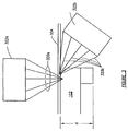
- Focused line heat to the front side and backside of the SSL 104 is focused onto the critical bend areas of the SSL 104.
- Focused line heaters 322a and 322b may be for example quartz heaters as produced by Research Inc., model # 5193.
- the more intense heat is preferably applied to the backside (bottom of the SSL in the illustration) of the SSL 104.
- Focused heat also may be applied to the front side (top of the SSL in the illustration) of the SSL 104.
- the focused heat 320a and 320b helps minimize the 'rippling' effect discussed hereinabove.
- FIG 4 a schematic elevational cross-section of the SSL being heated by conventional heat sources and protected by heat shields, according to another embodiment, is illustrated.
- Conventional ceramic or quartz heaters 422a (422b not shown) typically found on standard postforming machines may be used with this embodiment.
- Heat 420a and 420b (from heat sources 422a and 422b not shown) is applied to the area of the SSL 104 where the bending is to occur.
- the heat 420a and 420b is 'shielded' from the outer edges of the SSL 104 by using a heat shield 430, represented by upper portion 430a and lower portion 430b.
- the heat shield 430 may be manufactured from high heat resistant material (i.e., metal or other heat resistant material).
- the heat shield may be hollow or have channels therein for air or water cooling.
- the outer edge of the SSL 104 is thereby shielded from the heat 420a and 420b by passing between the upper portion 430a and the lower portion 430b of the heat shield 430.
- the heat shield 430 helps to substantially reduce rippling of the SSL 104, but the intense top heat 420a may still cause some particulate rise.
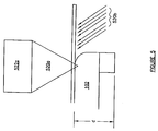
- FIG. 5 a schematic elevational cross-section view of a portion of SSL being heated at the bending area by a focused heat source at the front side and a conventional heat source at the backside of the SSL is illustrated.
- the SSL 104 is heated from both sides.
- Polymask film (not shown) may be applied to the surface (front side) of the SSL 104.
- the surface has focused line heating 520a where the bottom side of the SSL 104 has conventional heat 520b.
- the resulting bend may produce a front side (top) surface that may be acceptable depending on the edge radius attempted but postfinishing may be required.
- the surface material moves through a bending bar to a series of rollers (not illustrated) that help form it into the final required edge profile.
- the shape cut into the substrate edge (profile) and the position of these rollers dictate the final profile that the bent SSL 104 will assume. For each different profile, the position of these rollers will change.
- These rollers can be composed of rubber, silicone, or steel. These rollers typically do not conform to the shape of the final profile. These type of rollers will work but the preferred roller is contoured to assist the surface material in obtaining a tight fit to the final profile.
- edge finishing may be required on edge profiles sustaining particulate rise during the heating process of the methods disclosed hereinabove.
- Edge finishing can be achieved through a combination of profile sanding, more commonly known as belt and block sanding, and rotational sanding.
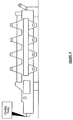
- Profile sanding removes particulate raise caused during postforming. Referring to Figure 6, a picture of a typical profile sander is illustrated.
- Profile sanders are commercially available from, for example, Delle Vedove, Hesseman, and Fletcher Machinery. They may require different belt and block configurations for each profile run. The number of profile sander stations needed is dependent on the profile (higher detail, more stations).
- An example of a semi-gloss finish on an SSL formed edge (three sanding steps are required): 220 grit sanding belt, 320 grit sanding belt and a very fine scotch-brite disc with waffle flanges.
- Profile sanding removes surface defects but leaves behind direction sanding lines. These direction lines follow parallel to the length of the substrate and can be difficult to remove by ordinary hand sanding. These lines have been successfully removed by rotation sanding.
- Rotational (spindle) sanders are commercially available from Fladder. These machines sand in a rotational motion to remove directional lines caused by profile sanding. Different types of finishes can be applied depending on what type of sand paper/scotch brite is placed on the rotational shaft.
- Coving may be an added step when a postformed countertop with a continuous backsplash is desired.
- Coving machines are manufactured by many of the same companies that produce postforming machines. Prior art heating of the surface of the laminate is with a heating rod that comes in direct contact with the surface of the laminate. It has been found that this type of heating will leave the SSL surface damaged (melting occurs). Standard coving machines may be used with SSL, but a few modifications to the operation of these coving machines is desirable.
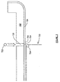
- FIG. 7 a schematic elevational cross-section view of a coving operation is illustrated.
- a portion 704 of the SSL 104 is being heated at the bending area by a heat source 722 spaced away from the backside of the SSL 104 and another rod shaped heat source 724 of a coving machine 730 is located on the front side of the SSL 104.
- a protective film 726 may be located between the surface of the SSL 104 and the rod shaped heat source 724.
- the radius of the heating rod 724 determines the cove radius.
- the SSL 104 has heat applied to both sides.
- the surface of the SSL 104 is preferably covered with the film 726, most preferably in the area where the heating rod 724 will be applied.
- the film 726 preferably is heat resistant above the temperature of the heating rod 724 so that it does not melt onto the surface of the SSL 104.
- the heating rod 724 is preferably set so that a temperature between 205 and 215 degrees Fahrenheit is maintained.
- the heater 722 is a radiant heater and is used to provide heat to the backside of the SSL 104 through the scored slot 728 in the substrate 102.
- the heater 722 on the backside of the SSL 104 is set so the surface temperature of the SSL 104 is greater than about 300 (149) to 320 (160) degrees Fahrenheit (° Celsius).
- the distance of the heater 722 preferably is about 1 inch from the substrate 102.
- the SSL 104 and the substrate 102 are thus exposed to this combination of heat from the heaters 722 and 724 until forming temperature is reached (same as postforming temperature disclosed hereinabove). Once the forming temperature is reached, the top of the SSL 104 is bent toward the heating rod 724 until a desired angle, such as for example 90 degree, bend is achieved. Once the SSL 104 has been bent, the backside heater 722 is moved and a cove stick (not illustrated) is installed with the substrate 102.
- the SSL 104 is heated only from the backside.
- the temperature of the heater 722 is dependent on the distance from the backside of the SSL 104, but the heat supplied should be such so that the SSL 104 surface reaches a temperature greater than 300 degrees Fahrenheit.
Landscapes
- Engineering & Computer Science (AREA)
- Manufacturing & Machinery (AREA)
- Physics & Mathematics (AREA)
- Thermal Sciences (AREA)
- Mechanical Engineering (AREA)
- Shaping Of Tube Ends By Bending Or Straightening (AREA)
- Laminated Bodies (AREA)
- Blow-Moulding Or Thermoforming Of Plastics Or The Like (AREA)
- Lining Or Joining Of Plastics Or The Like (AREA)
Applications Claiming Priority (2)
| Application Number | Priority Date | Filing Date | Title |
|---|---|---|---|
| US41926799A | 1999-10-15 | 1999-10-15 | |
| US419267 | 1999-10-15 |
Publications (2)
| Publication Number | Publication Date |
|---|---|
| EP1092528A2 true EP1092528A2 (de) | 2001-04-18 |
| EP1092528A3 EP1092528A3 (de) | 2001-04-25 |
Family
ID=23661523
Family Applications (1)
| Application Number | Title | Priority Date | Filing Date |
|---|---|---|---|
| EP00121954A Withdrawn EP1092528A3 (de) | 1999-10-15 | 2000-10-09 | Verfahren, vorrichtung und system zum nachträglichen formen von thermoplastplatten |
Country Status (6)
| Country | Link |
|---|---|
| EP (1) | EP1092528A3 (de) |
| JP (1) | JP2001150542A (de) |
| KR (1) | KR20010051015A (de) |
| CN (1) | CN1293106A (de) |
| AU (1) | AU5660800A (de) |
| CA (1) | CA2320505A1 (de) |
Cited By (9)
| Publication number | Priority date | Publication date | Assignee | Title |
|---|---|---|---|---|
| ES2264335A1 (es) * | 2004-08-02 | 2006-12-16 | Revesform S.A. | Procedimiento mejorado de revestimiento de perfiles de aluminio. |
| WO2012030751A3 (en) * | 2010-08-30 | 2012-06-14 | Corning Incorporated | Apparatus and method for shaping a glass substrate |
| WO2017049382A1 (en) * | 2015-09-23 | 2017-03-30 | Marc-André Racine | System and method for bending a hollow core sheet using rods |
| CN111516254A (zh) * | 2020-03-25 | 2020-08-11 | 科立视材料科技有限公司 | 3d玻璃贴膜装置及其工艺方法 |
| EP3778162A4 (de) * | 2018-03-30 | 2021-12-22 | Katomokuzai Kogyo Co., Ltd. | Herstellungsverfahren und herstellungsvorrichtung für beschichtetes produkt |
| EP3936338A1 (de) * | 2020-07-07 | 2022-01-12 | Jesús Francisco Barberan Latorre | Verfahren und system zum verkleben von substraten |
| JP7081035B1 (ja) | 2021-09-29 | 2022-06-06 | アイカ工業株式会社 | 連続式ポストフォーム加工装置及びポストフォーム加工品の製造方法。 |
| JP2023032070A (ja) * | 2021-08-26 | 2023-03-09 | アイカ工業株式会社 | 連続式ポストフォーム加工装置 |
| CN116900723A (zh) * | 2023-07-07 | 2023-10-20 | 南京钢铁股份有限公司 | 一种适用于高锰无磁钢的修磨轧制工艺 |
Families Citing this family (2)
| Publication number | Priority date | Publication date | Assignee | Title |
|---|---|---|---|---|
| CN102909813A (zh) * | 2012-10-15 | 2013-02-06 | 常州海川卓越密封材料有限公司 | 一种共混改性超疏水表面的制备方法 |
| CN108215413B (zh) * | 2017-12-29 | 2020-05-08 | 江苏澳盛复合材料科技有限公司 | 全表面具有编织纹理的可再塑型碳纤维板材及其制备方法 |
Family Cites Families (3)
| Publication number | Priority date | Publication date | Assignee | Title |
|---|---|---|---|---|
| DE2827361C2 (de) * | 1978-06-22 | 1981-12-03 | Metzeler Schaum Gmbh, 8940 Memmingen | Verfahren zum Beschichten eines Trägermaterials mit einer dekorativen Schichtstoffplatte |
| DE3736739A1 (de) * | 1987-10-30 | 1989-05-11 | Licentia Gmbh | Postformingverfahren und -vorrichtung |
| DE4311830A1 (de) * | 1993-04-14 | 1994-10-20 | Henkel Kgaa | Ummantelung von Kanten mit Beschichtungswerkstoffen |
-
2000
- 2000-09-08 AU AU56608/00A patent/AU5660800A/en not_active Abandoned
- 2000-09-18 CA CA002320505A patent/CA2320505A1/en not_active Abandoned
- 2000-10-09 EP EP00121954A patent/EP1092528A3/de not_active Withdrawn
- 2000-10-13 CN CN00130459A patent/CN1293106A/zh active Pending
- 2000-10-13 KR KR1020000060242A patent/KR20010051015A/ko not_active Ceased
- 2000-10-16 JP JP2000315498A patent/JP2001150542A/ja active Pending
Cited By (13)
| Publication number | Priority date | Publication date | Assignee | Title |
|---|---|---|---|---|
| ES2264335A1 (es) * | 2004-08-02 | 2006-12-16 | Revesform S.A. | Procedimiento mejorado de revestimiento de perfiles de aluminio. |
| ES2264335B1 (es) * | 2004-08-02 | 2007-11-16 | Revesform S.A. | Procedimiento mejorado de revestimiento de perfiles de aluminio. |
| WO2012030751A3 (en) * | 2010-08-30 | 2012-06-14 | Corning Incorporated | Apparatus and method for shaping a glass substrate |
| CN103068755A (zh) * | 2010-08-30 | 2013-04-24 | 康宁股份有限公司 | 用于成形玻璃基材的设备和方法 |
| WO2017049382A1 (en) * | 2015-09-23 | 2017-03-30 | Marc-André Racine | System and method for bending a hollow core sheet using rods |
| EP3778162A4 (de) * | 2018-03-30 | 2021-12-22 | Katomokuzai Kogyo Co., Ltd. | Herstellungsverfahren und herstellungsvorrichtung für beschichtetes produkt |
| CN111516254A (zh) * | 2020-03-25 | 2020-08-11 | 科立视材料科技有限公司 | 3d玻璃贴膜装置及其工艺方法 |
| EP3936338A1 (de) * | 2020-07-07 | 2022-01-12 | Jesús Francisco Barberan Latorre | Verfahren und system zum verkleben von substraten |
| EP4282620A3 (de) * | 2020-07-07 | 2024-02-21 | Jesús Francisco Barberan Latorre | Verfahren zum verkleben von substraten |
| JP2023032070A (ja) * | 2021-08-26 | 2023-03-09 | アイカ工業株式会社 | 連続式ポストフォーム加工装置 |
| JP7081035B1 (ja) | 2021-09-29 | 2022-06-06 | アイカ工業株式会社 | 連続式ポストフォーム加工装置及びポストフォーム加工品の製造方法。 |
| JP2023049069A (ja) * | 2021-09-29 | 2023-04-10 | アイカ工業株式会社 | 連続式ポストフォーム加工装置及びポストフォーム加工品の製造方法。 |
| CN116900723A (zh) * | 2023-07-07 | 2023-10-20 | 南京钢铁股份有限公司 | 一种适用于高锰无磁钢的修磨轧制工艺 |
Also Published As
| Publication number | Publication date |
|---|---|
| EP1092528A3 (de) | 2001-04-25 |
| CA2320505A1 (en) | 2001-04-15 |
| AU5660800A (en) | 2001-04-26 |
| JP2001150542A (ja) | 2001-06-05 |
| CN1293106A (zh) | 2001-05-02 |
| KR20010051015A (ko) | 2001-06-25 |
Similar Documents
| Publication | Publication Date | Title |
|---|---|---|
| AU718244B2 (en) | Aluminous press plate and process for producing same | |
| EP1092528A2 (de) | Verfahren, vorrichtung und system zum nachträglichen formen von thermoplastplatten | |
| JPH03224731A (ja) | 複合成形品の製造方法 | |
| TW478995B (en) | Method of polishing stainless steel laminate press plates to a nondirectional finish | |
| US8721396B1 (en) | Method for preparing and buffing a powder coated wood substrate | |
| US20230241800A1 (en) | Board edge casting process and application thereof | |
| KR20140096997A (ko) | 파우더 코팅 방법 및 파우더 코팅된 물품 | |
| ITTV950045A1 (it) | Procedimento perfezionato per nobilitare un pannello di legno povero particolarmente per la realizzazione di componenti d'arredamento, ed antina cosi' ottenuta. | |
| CN106413919A (zh) | 粉末涂覆方法和有待粉末涂覆的物品 | |
| US10286642B2 (en) | Bonded sheet molding composite automotive components without surface pre-treatment | |
| AU2011269654A1 (en) | A coated laminate material and a method of fabricating therefor | |
| RU2048289C1 (ru) | Способ изготовления древесностружечных плит с двухсторонней облицовкой | |
| CN102271883A (zh) | 用于用天然木质层包覆三维制品的表面的方法 | |
| KR100793379B1 (ko) | 멜라민 수지 함침층을 갖는 판재 표면에 고광택 유브이고팅층을 형성하는 제조방법 및 그에 의해 제조된 판재 | |
| JPH02277602A (ja) | 化粧材用単板及び化粧材の製造方法 | |
| JP2001182276A (ja) | 鏡面性化粧板および鏡面性化粧板の製造方法 | |
| KR200425829Y1 (ko) | 멜라민 수지 함침층을 갖는 판재 표면에 고광택 유브이고팅층을 형성하여 된 판재 | |
| CN103917345A (zh) | 粉末涂覆方法以及被涂覆粉末的工件 | |
| JP2004249585A (ja) | 繊維強化プラスチック成形体およびその製造方法 | |
| JP2736722B2 (ja) | 化粧パネルの製造方法 | |
| KR100538752B1 (ko) | 가구용 문짝의 제조방법 | |
| JP2001310413A (ja) | 窯業系化粧板及びその製造方法 | |
| JPH04229255A (ja) | 化粧材の製造方法 | |
| RU2400355C1 (ru) | Способ изготовления облицованной гнутой детали фасада | |
| JPH08300593A (ja) | 化粧板の製法 |
Legal Events
| Date | Code | Title | Description |
|---|---|---|---|
| PUAI | Public reference made under article 153(3) epc to a published international application that has entered the european phase |
Free format text: ORIGINAL CODE: 0009012 |
|
| PUAL | Search report despatched |
Free format text: ORIGINAL CODE: 0009013 |
|
| 17P | Request for examination filed |
Effective date: 20001011 |
|
| AK | Designated contracting states |
Kind code of ref document: A2 Designated state(s): AT BE CH CY DE DK ES FI FR GB GR IE IT LI LU MC NL PT SE |
|
| AX | Request for extension of the european patent |
Free format text: AL;LT;LV;MK;RO;SI |
|
| AK | Designated contracting states |
Kind code of ref document: A3 Designated state(s): AT BE CH CY DE DK ES FI FR GB GR IE IT LI LU MC NL PT SE |
|
| AX | Request for extension of the european patent |
Free format text: AL;LT;LV;MK;RO;SI |
|
| RIN1 | Information on inventor provided before grant (corrected) |
Inventor name: TRETHEWEY, BRUCE RODNEY, JR. Inventor name: BILLECK, BILLY JOE, JR. Inventor name: INGRIM, MICHAEL A. Inventor name: OWENS, DAVID M. Inventor name: MOORE, STEVEN J. Inventor name: MOORE, KELLY Inventor name: RABROKER, BETH, A. |
|
| AKX | Designation fees paid |
Free format text: AT BE CH CY DE DK ES FI FR GB GR IE IT LI LU MC NL PT SE |
|
| 17Q | First examination report despatched |
Effective date: 20020220 |
|
| STAA | Information on the status of an ep patent application or granted ep patent |
Free format text: STATUS: THE APPLICATION IS DEEMED TO BE WITHDRAWN |
|
| 18D | Application deemed to be withdrawn |
Effective date: 20020703 |