EP1092811B1 - Améliorations relatives aux moyens de fixation - Google Patents
Améliorations relatives aux moyens de fixation Download PDFInfo
- Publication number
- EP1092811B1 EP1092811B1 EP00308953A EP00308953A EP1092811B1 EP 1092811 B1 EP1092811 B1 EP 1092811B1 EP 00308953 A EP00308953 A EP 00308953A EP 00308953 A EP00308953 A EP 00308953A EP 1092811 B1 EP1092811 B1 EP 1092811B1
- Authority
- EP
- European Patent Office
- Prior art keywords
- clip
- fastener
- stud
- horizontal leg
- fingers
- Prior art date
- Legal status (The legal status is an assumption and is not a legal conclusion. Google has not performed a legal analysis and makes no representation as to the accuracy of the status listed.)
- Expired - Lifetime
Links
- 235000001674 Agaricus brunnescens Nutrition 0.000 claims abstract description 8
- 230000015572 biosynthetic process Effects 0.000 claims description 7
- 239000002184 metal Substances 0.000 claims description 5
- 238000005755 formation reaction Methods 0.000 description 4
- 238000010276 construction Methods 0.000 description 1
- 239000002991 molded plastic Substances 0.000 description 1
- 238000007789 sealing Methods 0.000 description 1
- 210000002105 tongue Anatomy 0.000 description 1
Images
Classifications
-
- E—FIXED CONSTRUCTIONS
- E03—WATER SUPPLY; SEWERAGE
- E03C—DOMESTIC PLUMBING INSTALLATIONS FOR FRESH WATER OR WASTE WATER; SINKS
- E03C1/00—Domestic plumbing installations for fresh water or waste water; Sinks
- E03C1/12—Plumbing installations for waste water; Basins or fountains connected thereto; Sinks
- E03C1/32—Holders or supports for basins
- E03C1/33—Fastening sinks or basins in an apertured support
- E03C1/335—Fastening sinks or basins in an apertured support the fastening means comprising a screw
-
- E—FIXED CONSTRUCTIONS
- E03—WATER SUPPLY; SEWERAGE
- E03C—DOMESTIC PLUMBING INSTALLATIONS FOR FRESH WATER OR WASTE WATER; SINKS
- E03C1/00—Domestic plumbing installations for fresh water or waste water; Sinks
- E03C1/12—Plumbing installations for waste water; Basins or fountains connected thereto; Sinks
- E03C1/32—Holders or supports for basins
- E03C1/33—Fastening sinks or basins in an apertured support
Definitions
- This invention relates to fasteners. It is primarily concerned with fasteners for sinks or basins which are set down into an aperture in a worktop, the rim being a flange that rests on the periphery of the aperture and which is clamped in place by devices fitted underneath the sink or basin. It is a development of the fastener described in our Patents EP GB-B-0 128 772 and GB-B-2 285 480.
- the fasteners described in the first Patent were designed for metal sinks which provide slim ribs or tags projecting downwardly and onto which the fasteners can clip,
- the second Patent is concerned with fasteners for moulded plastics sinks which could provide underside formations with horizontal slots into which barbed tongues could enter and thus make the fasteners captive.
- EP-A-0271705 discloses a fastener of similar form to that shown in EP-B-0128722 and is designed for vertical, edgewise engagement with a downwardly projecting wall on a sink.
- other sink constructions are proposed which require different fasteners, and it is the aim of this invention to provide one such alternative.
- a fastener comprising a clip, a clamping member hinged thereto and means for adjusting the clamping member relative to the clip in a direction transverse to the hinge axis, wherein the clip is of inverted L-shape with the horizontal leg providing a formation which can laterally engage and retentively snap around the stem of an inverted mushroom stud.
- the clip will be of sheet metal.
- the horizontal leg has four fingers extending away from the angle of the L, the middle two fingers being said formation. These fingers need to be quite narrow to flex satisfactorily during the snap action, and the outer two fingers add width to the horizontal leg, and therefore stability of engagement with the underside of the rim of the sink unit.
- the horizontal leg has a closed end slot with a wide end portion through which the head of a mushroom stud can pass and a narrow end portion into which the stem of the stud can snap.
- the closed end of the narrow end portion will preferably be adjacent the free end of the horizontal leg and the wide end portion may extend into the vertical leg of the L-shaped clip. Indeed, it can be an extension of a slot in that portion which is provided to accommodate a screw by which the clamping member is adjusted.
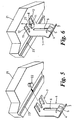
- the horizontal leg of the L-shaped clip may bow downwardly in the region of said formation. Then, while the upper face of the leg engages the underside of the sink unit, the downward bow wedges against the head of the mushroom stud and tends to be flattened slightly as the snap fastening is completed.
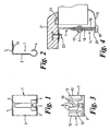
- the upper part of the fastener of Figures 1 to 6 is a clip 1 formed from a single substantially rectangular sheet of metal having a certain resilience and bent and cut in a manner described below.
- the clip 1 is of inverted L-shape with the upright leg 2 terminating at its lower end in a partial roll 3 with a central extension 4 to an almost complete roll.
- This roll has a central slot 5 and a further slot 6 is formed from near the end of this slot to near the centre of the top of the portion 2.
- the horizontal leg 7 of the clip has a set of four parallel fingers extending away from the angle of the L, the two inner ones 8 being separated by a divergent slot 9 with opposed arcuate enlargements 10 at an intermediate position. In the region of these enlargements the fingers 8 are locally bowed downwards at 11.
- the outer fingers 12 are separated from the inner fingers 8 by slots 13 which allow the fingers 8 to flex slightly apart.
- the clamping member 14 (shown only in Figure 4) is similar to the one described in EP (GB) 0 128 772. It is generally L-shaped in side view with a lower flange 15 having upturned corners for engaging under a worktop.
- the upright portion comprises two fingers 16 which engage in diametral slots in opposite ends of a hinge pin 17 and which pass freely either side of the extension 4.
- the hinge pin 17 is captive in the roll 3 and its extension 4.
- a screw 18 has its head 19 engaging under a central lug 20 at the root of the flange 15 and extends upwardly, parallel to and midway between the fingers 16. It engages through the centre of the hinge pin 17 and is unimpeded by the extension 4 and the portion 2 by virtue of the slots 5 and 6.
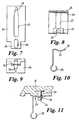
- an alternative clip is made from a sheet metal blank 24, generally rectangular but with a substantially square extension 25 centrally at one end equivalent to the extension 4 and serving the same purpose. It has a slot 26 through which the screw will pass.
- a bottle-shaped slot 27 part of which is equivalent to the slot 6. It has a rounded base adjacent the extension 25 and its neck tapers in towards the other end, and to opposed arcuate enlargements 28 equivalent to the enlargements 10. Beyond them the slot 27 is parallel sided up to its rounded, closed end.
- This blank 24 is deformed into L-shaped like the clip 1 and the neck of the slot 27 is in the horizontal leg 29 of what is now a clip. In the region of the enlargements 28 this leg 29 is bowed downwards as a shallow rib 30 transverse of the clip.
- a stud 31 which is to be engaged by this clip is similar to the stud 22 except that it offers an annular groove 32 a short distance below the underside of a rim 33 of a sink, rather than a simple mushroom head.
- the lower end 34 of the stud 31, beyond the groove 32, is cylindrical and of slightly less diameter than the width of the slot 27. It can therefore pass through the slot 27 where the neck begins in the horizontal leg 29, and the clip is offered up accordingly (to the right of the position shown in Figure 11). The clip is then pulled towards the edge of the rim 33 and the groove 32 is engaged by the edges defining the neck. Finally, the enlargements 28 snap around the stud 31 within the groove 32 and the clip is secure.
Landscapes
- Engineering & Computer Science (AREA)
- Environmental & Geological Engineering (AREA)
- Health & Medical Sciences (AREA)
- Life Sciences & Earth Sciences (AREA)
- Hydrology & Water Resources (AREA)
- Public Health (AREA)
- Water Supply & Treatment (AREA)
- Clamps And Clips (AREA)
- Dowels (AREA)
Claims (6)
- Moyen de fixation comprenant un élément de retenue (1), un élément de serrage (14) articulé à celui-ci et un moyen (18) pour ajuster l'élément de serrage (14) par rapport à l'élément de retenue (1) dans une direction transversale à l'axe d'articulation, caractérisé par le fait que l'élément de retenue (1) dans sa position installée a la forme d'un L renversé avec une branche horizontale (7, 29) fournissant une formation (8, 27) qui peut s'engager latéralement et s'encliqueter de façon sûre autour d'une tige d'une protubérance en champignon renversé (22 ; 31).
- Moyen de fixation selon la revendication 1, dans lequel l'élément de retenue (1) est de tôle métallique.
- Moyen de fixation selon la revendication 2, dans lequel la branche horizontale (7) a quatre doigts (8, 12) s'étendant à l'opposé de l'angle du L, les deux doigts du milieu (8) étant ladite formation.
- Moyen de fixation selon la revendication 2, dans lequel la branche horizontale (29) a une fente (27) à extrémité fermée avec une partie d'extrémité large à travers laquelle la tête d'une protubérance en champignon (31) peut passer et une partie d'extrémité étroite (28) dans laquelle la tige de la protubérance peut s'encliqueter.
- Moyen de fixation selon la revendication 4, dans lequel l'extrémité fermée de la partie d'extrémité étroite (28) est adjacente à l'extrémité libre de la branche horizontale (29) et la partie d'extrémité large s'étend dans la branche verticale de l'élément de retenue en forme de L.
- Moyen de fixation selon l'une quelconque des revendications 2 à 6, dans lequel la branche horizontale (7, 9) se courbe dans la position installée vers le bas dans la région de ladite formation.
Applications Claiming Priority (4)
| Application Number | Priority Date | Filing Date | Title |
|---|---|---|---|
| GBGB9924080.6A GB9924080D0 (en) | 1999-10-13 | 1999-10-13 | Improvements relating to fasteners |
| GB9924080 | 1999-10-13 | ||
| GB0020663A GB2355284B (en) | 1999-10-13 | 2000-08-23 | Improvements relating to fasteners |
| GB0020663 | 2000-08-23 |
Publications (3)
| Publication Number | Publication Date |
|---|---|
| EP1092811A2 EP1092811A2 (fr) | 2001-04-18 |
| EP1092811A3 EP1092811A3 (fr) | 2002-12-18 |
| EP1092811B1 true EP1092811B1 (fr) | 2005-06-22 |
Family
ID=26244882
Family Applications (1)
| Application Number | Title | Priority Date | Filing Date |
|---|---|---|---|
| EP00308953A Expired - Lifetime EP1092811B1 (fr) | 1999-10-13 | 2000-10-11 | Améliorations relatives aux moyens de fixation |
Country Status (3)
| Country | Link |
|---|---|
| EP (1) | EP1092811B1 (fr) |
| AT (1) | ATE298383T1 (fr) |
| DE (1) | DE60020924D1 (fr) |
Families Citing this family (2)
| Publication number | Priority date | Publication date | Assignee | Title |
|---|---|---|---|---|
| US9683357B2 (en) * | 2014-07-18 | 2017-06-20 | Jeffrey M Provencher | System and method for installing an undermount sink |
| DE102014224929A1 (de) * | 2014-12-04 | 2016-06-09 | Bayerische Motoren Werke Aktiengesellschaft | Clipwave System |
Family Cites Families (6)
| Publication number | Priority date | Publication date | Assignee | Title |
|---|---|---|---|---|
| US3438664A (en) * | 1967-11-07 | 1969-04-15 | Warren Fastener Corp | Structural assembly and clip |
| GB2010376B (en) * | 1977-11-30 | 1982-04-15 | Itw Inc | Clips |
| EP0066140B1 (fr) * | 1981-06-02 | 1984-10-24 | Niro Plan Ag | Dispositif de serrage spécialement pour fixer un évier à encastrer |
| GB8316170D0 (en) | 1983-06-14 | 1983-07-20 | Springfast Ltd | Fasteners |
| DE3643488A1 (de) * | 1986-12-19 | 1988-06-30 | Niro Plan Ag | Befestigungsglied zur montage einer kuechenspuele oder dergl. |
| GB9400125D0 (en) | 1994-01-06 | 1994-03-02 | Springfast Ltd | Improvements relating to fasteners |
-
2000
- 2000-10-11 EP EP00308953A patent/EP1092811B1/fr not_active Expired - Lifetime
- 2000-10-11 AT AT00308953T patent/ATE298383T1/de not_active IP Right Cessation
- 2000-10-11 DE DE60020924T patent/DE60020924D1/de not_active Expired - Lifetime
Also Published As
| Publication number | Publication date |
|---|---|
| DE60020924D1 (de) | 2005-07-28 |
| EP1092811A2 (fr) | 2001-04-18 |
| EP1092811A3 (fr) | 2002-12-18 |
| ATE298383T1 (de) | 2005-07-15 |
Similar Documents
| Publication | Publication Date | Title |
|---|---|---|
| US4133509A (en) | Article mounting assembly | |
| US4712959A (en) | Washer with resilient head cripping means | |
| JP3342190B2 (ja) | 物品の保持具 | |
| CA1228973A (fr) | Organe de fixation | |
| US5056196A (en) | Pipe-clip | |
| US4504986A (en) | Sink mounting | |
| US5991152A (en) | CPU heat sink fastener | |
| EP3655611A1 (fr) | Dispositif d'écran | |
| US5256018A (en) | Clip-on fastener | |
| US20030122115A1 (en) | Fence post cap | |
| EP1092811A2 (fr) | Améliorations relatives aux moyens de fixation | |
| GB2355284A (en) | Sink unit fasteners | |
| US6602035B1 (en) | Fastener with hinged-clamping element | |
| US20050141956A1 (en) | Device for fastening a part, such as a trough, to a support part, such as a support plate | |
| KR0169895B1 (ko) | 지지용 다리 | |
| GB2285480A (en) | Fasteners for sink units | |
| JPH0522410Y2 (fr) | ||
| JPH0638460Y2 (ja) | コード止め具 | |
| JPS6018650Y2 (ja) | 留め具 | |
| GB2265168A (en) | Pole top cover expandable bracket assembly | |
| KR880000896Y1 (ko) | 출입문용 멈춤구 | |
| KR200281185Y1 (ko) | 가구용 힌지의 힌지컵 | |
| EP1465512B1 (fr) | Structure permettant de suspendre des pots de fleurs sur des garde-corps de balcons et analogues | |
| JPH10227106A (ja) | 軒樋吊具 | |
| GB2640458A (en) | Door stay apparatus |
Legal Events
| Date | Code | Title | Description |
|---|---|---|---|
| PUAI | Public reference made under article 153(3) epc to a published international application that has entered the european phase |
Free format text: ORIGINAL CODE: 0009012 |
|
| AK | Designated contracting states |
Kind code of ref document: A2 Designated state(s): AT BE CH CY DE DK ES FI FR GB GR IE IT LI LU MC NL PT SE |
|
| AX | Request for extension of the european patent |
Free format text: AL;LT;LV;MK;RO;SI |
|
| PUAL | Search report despatched |
Free format text: ORIGINAL CODE: 0009013 |
|
| AK | Designated contracting states |
Kind code of ref document: A3 Designated state(s): AT BE CH CY DE DK ES FI FR GB GR IE IT LI LU MC NL PT SE |
|
| AX | Request for extension of the european patent |
Free format text: AL;LT;LV;MK;RO;SI |
|
| RIC1 | Information provided on ipc code assigned before grant |
Free format text: 7E 03C 1/33 A, 7F 16B 2/24 B |
|
| 17P | Request for examination filed |
Effective date: 20030123 |
|
| AKX | Designation fees paid |
Designated state(s): AT BE CH CY DE DK ES FI FR GB GR IE IT LI LU MC NL PT SE |
|
| 17Q | First examination report despatched |
Effective date: 20031106 |
|
| GRAP | Despatch of communication of intention to grant a patent |
Free format text: ORIGINAL CODE: EPIDOSNIGR1 |
|
| GRAS | Grant fee paid |
Free format text: ORIGINAL CODE: EPIDOSNIGR3 |
|
| GRAA | (expected) grant |
Free format text: ORIGINAL CODE: 0009210 |
|
| AK | Designated contracting states |
Kind code of ref document: B1 Designated state(s): AT BE CH CY DE DK ES FI FR GB GR IE IT LI LU MC NL PT SE |
|
| PG25 | Lapsed in a contracting state [announced via postgrant information from national office to epo] |
Ref country code: BE Free format text: LAPSE BECAUSE OF FAILURE TO SUBMIT A TRANSLATION OF THE DESCRIPTION OR TO PAY THE FEE WITHIN THE PRESCRIBED TIME-LIMIT Effective date: 20050622 Ref country code: IT Free format text: LAPSE BECAUSE OF FAILURE TO SUBMIT A TRANSLATION OF THE DESCRIPTION OR TO PAY THE FEE WITHIN THE PRE;WARNING: LAPSES OF ITALIAN PATENTS WITH EFFECTIVE DATE BEFORE 2007 MAY HAVE OCCURRED AT ANY TIME BEFORE 2007. THE CORRECT EFFECTIVE DATE MAY BE DIFFERENT FROM THE ONE RECORDED.SCRIBED TIME-LIMIT Effective date: 20050622 Ref country code: LI Free format text: LAPSE BECAUSE OF FAILURE TO SUBMIT A TRANSLATION OF THE DESCRIPTION OR TO PAY THE FEE WITHIN THE PRESCRIBED TIME-LIMIT Effective date: 20050622 Ref country code: CH Free format text: LAPSE BECAUSE OF FAILURE TO SUBMIT A TRANSLATION OF THE DESCRIPTION OR TO PAY THE FEE WITHIN THE PRESCRIBED TIME-LIMIT Effective date: 20050622 Ref country code: NL Free format text: LAPSE BECAUSE OF FAILURE TO SUBMIT A TRANSLATION OF THE DESCRIPTION OR TO PAY THE FEE WITHIN THE PRESCRIBED TIME-LIMIT Effective date: 20050622 Ref country code: AT Free format text: LAPSE BECAUSE OF FAILURE TO SUBMIT A TRANSLATION OF THE DESCRIPTION OR TO PAY THE FEE WITHIN THE PRESCRIBED TIME-LIMIT Effective date: 20050622 Ref country code: ES Free format text: LAPSE BECAUSE OF FAILURE TO SUBMIT A TRANSLATION OF THE DESCRIPTION OR TO PAY THE FEE WITHIN THE PRESCRIBED TIME-LIMIT Effective date: 20050622 Ref country code: FI Free format text: LAPSE BECAUSE OF FAILURE TO SUBMIT A TRANSLATION OF THE DESCRIPTION OR TO PAY THE FEE WITHIN THE PRESCRIBED TIME-LIMIT Effective date: 20050622 |
|
| REG | Reference to a national code |
Ref country code: GB Ref legal event code: FG4D |
|
| REG | Reference to a national code |
Ref country code: CH Ref legal event code: EP |
|
| REG | Reference to a national code |
Ref country code: IE Ref legal event code: FG4D |
|
| REF | Corresponds to: |
Ref document number: 60020924 Country of ref document: DE Date of ref document: 20050728 Kind code of ref document: P |
|
| PG25 | Lapsed in a contracting state [announced via postgrant information from national office to epo] |
Ref country code: DK Free format text: LAPSE BECAUSE OF FAILURE TO SUBMIT A TRANSLATION OF THE DESCRIPTION OR TO PAY THE FEE WITHIN THE PRESCRIBED TIME-LIMIT Effective date: 20050922 Ref country code: SE Free format text: LAPSE BECAUSE OF FAILURE TO SUBMIT A TRANSLATION OF THE DESCRIPTION OR TO PAY THE FEE WITHIN THE PRESCRIBED TIME-LIMIT Effective date: 20050922 Ref country code: GR Free format text: LAPSE BECAUSE OF FAILURE TO SUBMIT A TRANSLATION OF THE DESCRIPTION OR TO PAY THE FEE WITHIN THE PRESCRIBED TIME-LIMIT Effective date: 20050922 |
|
| PG25 | Lapsed in a contracting state [announced via postgrant information from national office to epo] |
Ref country code: DE Free format text: LAPSE BECAUSE OF FAILURE TO SUBMIT A TRANSLATION OF THE DESCRIPTION OR TO PAY THE FEE WITHIN THE PRESCRIBED TIME-LIMIT Effective date: 20050923 |
|
| PG25 | Lapsed in a contracting state [announced via postgrant information from national office to epo] |
Ref country code: CY Free format text: LAPSE BECAUSE OF FAILURE TO SUBMIT A TRANSLATION OF THE DESCRIPTION OR TO PAY THE FEE WITHIN THE PRESCRIBED TIME-LIMIT Effective date: 20051011 Ref country code: IE Free format text: LAPSE BECAUSE OF NON-PAYMENT OF DUE FEES Effective date: 20051011 |
|
| PG25 | Lapsed in a contracting state [announced via postgrant information from national office to epo] |
Ref country code: MC Free format text: LAPSE BECAUSE OF NON-PAYMENT OF DUE FEES Effective date: 20051031 Ref country code: LU Free format text: LAPSE BECAUSE OF NON-PAYMENT OF DUE FEES Effective date: 20051031 |
|
| PG25 | Lapsed in a contracting state [announced via postgrant information from national office to epo] |
Ref country code: PT Free format text: LAPSE BECAUSE OF FAILURE TO SUBMIT A TRANSLATION OF THE DESCRIPTION OR TO PAY THE FEE WITHIN THE PRESCRIBED TIME-LIMIT Effective date: 20051129 |
|
| NLV1 | Nl: lapsed or annulled due to failure to fulfill the requirements of art. 29p and 29m of the patents act | ||
| REG | Reference to a national code |
Ref country code: CH Ref legal event code: PL |
|
| PLBE | No opposition filed within time limit |
Free format text: ORIGINAL CODE: 0009261 |
|
| STAA | Information on the status of an ep patent application or granted ep patent |
Free format text: STATUS: NO OPPOSITION FILED WITHIN TIME LIMIT |
|
| 26N | No opposition filed |
Effective date: 20060323 |
|
| REG | Reference to a national code |
Ref country code: IE Ref legal event code: MM4A |
|
| EN | Fr: translation not filed | ||
| PG25 | Lapsed in a contracting state [announced via postgrant information from national office to epo] |
Ref country code: FR Free format text: LAPSE BECAUSE OF FAILURE TO SUBMIT A TRANSLATION OF THE DESCRIPTION OR TO PAY THE FEE WITHIN THE PRESCRIBED TIME-LIMIT Effective date: 20060818 |
|
| PG25 | Lapsed in a contracting state [announced via postgrant information from national office to epo] |
Ref country code: FR Free format text: LAPSE BECAUSE OF FAILURE TO SUBMIT A TRANSLATION OF THE DESCRIPTION OR TO PAY THE FEE WITHIN THE PRESCRIBED TIME-LIMIT Effective date: 20051031 |
|
| PG25 | Lapsed in a contracting state [announced via postgrant information from national office to epo] |
Ref country code: FR Free format text: LAPSE BECAUSE OF FAILURE TO SUBMIT A TRANSLATION OF THE DESCRIPTION OR TO PAY THE FEE WITHIN THE PRESCRIBED TIME-LIMIT Effective date: 20050622 |
|
| PGFP | Annual fee paid to national office [announced via postgrant information from national office to epo] |
Ref country code: GB Payment date: 20141029 Year of fee payment: 15 |
|
| GBPC | Gb: european patent ceased through non-payment of renewal fee |
Effective date: 20151011 |
|
| PG25 | Lapsed in a contracting state [announced via postgrant information from national office to epo] |
Ref country code: GB Free format text: LAPSE BECAUSE OF NON-PAYMENT OF DUE FEES Effective date: 20151011 |