EP1092871A2 - Taumelscheibenkompressorhohlkolben mit Bohrungen - Google Patents
Taumelscheibenkompressorhohlkolben mit Bohrungen Download PDFInfo
- Publication number
- EP1092871A2 EP1092871A2 EP00119744A EP00119744A EP1092871A2 EP 1092871 A2 EP1092871 A2 EP 1092871A2 EP 00119744 A EP00119744 A EP 00119744A EP 00119744 A EP00119744 A EP 00119744A EP 1092871 A2 EP1092871 A2 EP 1092871A2
- Authority
- EP
- European Patent Office
- Prior art keywords
- swash plate
- piston
- unilateral
- plate type
- type compressor
- Prior art date
- Legal status (The legal status is an assumption and is not a legal conclusion. Google has not performed a legal analysis and makes no representation as to the accuracy of the status listed.)
- Withdrawn
Links
Images


Classifications
-
- F—MECHANICAL ENGINEERING; LIGHTING; HEATING; WEAPONS; BLASTING
- F04—POSITIVE - DISPLACEMENT MACHINES FOR LIQUIDS; PUMPS FOR LIQUIDS OR ELASTIC FLUIDS
- F04B—POSITIVE-DISPLACEMENT MACHINES FOR LIQUIDS; PUMPS
- F04B27/00—Multi-cylinder pumps specially adapted for elastic fluids and characterised by number or arrangement of cylinders
- F04B27/08—Multi-cylinder pumps specially adapted for elastic fluids and characterised by number or arrangement of cylinders having cylinders coaxial with, or parallel or inclined to, main shaft axis
- F04B27/0873—Component parts, e.g. sealings; Manufacturing or assembly thereof
- F04B27/0878—Pistons
Definitions
- the present invention relates to a unilateral-headed swash plate type compressor used for the air-conditioning of automobiles or the like.
- the piston has a shoe coupler integrally formed with the body thereof in sliding contact with the inner peripheral surface of the cylinder bore, and the shoe is placed between the shoe coupler and the swash plate.
- These unilateral swash plate type compressors are adapted to change the piston stroke and the inclination angle of the swash plate in accordance with the difference between the internal pressure of the crank chamber and the suction pressure thereby to control the compression capacity.
- a cavity for reducing the weight is formed in the piston body and a piston ring for improving the hermeticity is fitted in an annular groove of the piston body in sliding contact with the inner peripheral surface of the cylinder bore.
- a hollow portion or a cut-out portion is disclosed as the cavity.
- the swash plate In these unilateral-headed swash plate type compressors, the swash plate is rotated synchronously with the drive shaft driven by the external drive source, so that the piston is reciprocated in the cylinder bore through the shoes. As a result, the cylinder bore forms a compression chamber with the piston head.
- a low-pressure refrigerant gas is introduced into the compression chamber from the suction chamber connected to the evaporator of a refrigeration circuit.
- a high-pressure refrigerant gas is discharged into the discharge chamber from the compression chamber.
- the discharge chamber is connected to a condenser of the refrigeration circuit, which constitutes a vehicle air-conditioning system used for air-conditioning of the automotive vehicle.
- the inclination angle of the swash plate is required to be reduced in the case where the operating switch of the vehicle air-conditioning system is turned off or the cooling function is otherwise stopped in response to an external command.
- the internal pressure of the crank case must be increased to secure a higher back pressure exerted on the swash plate.
- considerable time is required to reduce the inclination angle of the swash plate and the transition to the minimum capacity is delayed if only a small amount of the blowby gas is supplied into the crank chamber at a time. This causes unnecessary refrigeration to continue or an unnecessary load to be imposed on the external drive source.
- the present invention has been developed in view of this situation, and a object thereof is to provide a unilateral-headed swash plate type compressor, with improved durability, utilizing the features of the cavity and the piston ring.
- Another object of the invention is to assure quick transition to minimum capacity for the unilateral swash plate type compressor with variable displacement.
- a unilateral-headed swash plate type compressor comprising:
- the weight thereof is reduced by the cavity formed in the piston.
- a hollow portion or a cut-out portion can be employed as the cavity.
- an annular groove is formed in the piston body and a piston ring is fitted in the annular groove, so that the refrigerant gas compressed in the cylinder bore can be discharged efficiently into the discharge chamber.
- the unilateral-headed swash plate type compressor according to this invention also has at least one through hole in the piston body, which through hole opens to the inner peripheral surface of the cylinder bore and communicates with the crank chamber through the cavity.
- the refrigerant gas is easily supplied from the compressor chamber into the crank chamber as a blowby gas.
- the refrigerant gas is conveniently passed through the cavity formed in the piston, and therefore the need of a special path for the refrigerant gas is eliminated to reduce the manufacturing cost.
- the lubricant mist contained in the refrigerant gas is also easily supplied to the sliding portions between the swash plate and the shoes and between the piston and the shoes.
- the sliding portions are not easily worn and have a high durability.
- the unilateral-headed swash plate type compressor according to the invention can be improved in durability taking advantage of the feature of the cavity and the piston ring.
- a unilateral-headed swash plate type compressor according to first to fifth embodiments of the invention will be described with reference to the drawings.
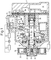
- a cup-shaped front housing 2 is coupled to the front end of a cylinder block 1 formed with a plurality of cylinder bores 1a, an axial hole 1b, a muffler chamber 1c and a suction chamber 1d.
- the rear end of the cylinder block 1 is coupled to a rear housing 7 holding a suction valve 3, a valve plate 4, a discharge valve 5 and a retainer 6.
- the cylinder block 1, the front housing 2 and the rear housing 7 make up a housing.
- An axial hole 2a is also formed in the front housing 2.
- a drive shaft 12 is supported rotatably in the axial hole 2a through a shaft seal unit 9 and a radial bearing 10 and also in the axial hole 1b of the cylinder block 1 through a radial bearing 11.
- a lug plate 14 is fixed on the drive shaft 12 in the space between it and the front housing 2 through a thrust bearing 13.
- a pair of arms 15 are protruded rearward from the lug plate 14, and a guide hole 15a having a cylindrical inner surface is formed through each arm 15.
- the drive shaft 12 is inserted in a through hole 16a of the swash plate 16, and an inclination angle reducing spring 17 is interposed between the swash plate 16 and the lug plate 14.
- the swash plate 16 is urged in such a direction that the inclination angle is reduced from maximum to minimum value by the inclination angle reducing spring 17.
- a pair of guide pins 16b are protruded from the front end of the swash plate 16 toward each arm 15, and a guide unit 16c having a spherical outer surface rotatable while sliding within the guide hole 15a is formed at the forward end of each guide pin 16b.
- pistons 19 are arranged through a pair of shoes 18 at the front and rear peripheral edges, respectively, of the swash plate 16. Each piston 19 is accommodated in a corresponding cylinder bore 1a.
- a boss 20 is fitted, by splining, onto the drive shaft 12 protruded forward from the front housing 2.
- the boss 20 is fixed with a pulley 22 by means of a key 21.
- the pulley 22 is fixed by a bolt 23 with the drive shaft 12 on the one hand and supported by a bearing 24 with the front housing 2 on the other.
- the pulley 22 is wound with a belt 34 connected to an engine EG constituting an external drive source.
- a resilient spring 26 is arranged with a snap ring 25 on the portion of the drive shaft 12 somewhat behind the swash plate 16.
- a thrust bearing 27 and a washer 28 are arranged at the rear end of the drive shaft 12, and a spring 29 is interposed between the washer 28 and the suction valve 3.
- the suction chamber 7a communicates with each cylinder bore 1a by way of a suction port 30 formed through the retainer 6, the discharge valve 5 and the valve plate 4.
- the suction chamber 1d is connected to the evaporator EV of an external refrigeration circuit by a pipe, and the evaporator EV in turn is connected by a pipe to a condenser CO through an expansion valve V.
- a discharge chamber 7b is formed outside the rear housing 7.
- the discharge chamber 7b and the muffler chamber 1c of the cylinder block 1 communicate with each other through a discharge passage 7c formed through the retainer 6, the discharge valve 5, the valve plate 4 and the suction valve 3.
- the muffler chamber 1c is connected by pipe to the condenser Co of the refrigeration circuit.
- the discharge chamber 7b communicates with each cylinder bore 1a by a discharge port 31 formed through the valve plate 4 and the suction valve 3.
- a control valve 32 is accommodated in the rear housing 7.
- a hollow portion 19a for realizing a reduced weight is formed as a cavity in the body 19c of the piston 19 in sliding contact with the inner peripheral surface of the cylinder bore 1a.
- the portion of the body 19c nearer to the head is formed with an annular groove 42.
- a piston ring 41 in sliding contact with the inner peripheral surface of the cylinder bore 1a is fitted in the annular groove 42 as shown in Fig. 1.
- each annular ring 42 is formed with a plurality of first holes 46 for connecting the inner peripheral surface of the cylinder bore 1a and the hollow portion 19a.
- the first holes 46 are formed along the diameter at equal angular intervals with respect to the periphery of the piston 19.
- the piston 19 includes a shoe coupler 19b integrated with the piston body 19c for coupling the shoe 18.
- the portion of the body 19c nearer to the shoe coupler 19b is formed with second holes 48 communicating with the first holes 46 through the hollow portion 19a and connecting the hollow portion 19a with the crank chamber 8. More specifically, the second holes 48 are obliquely formed in the neighborhood of the shoe 18 under the shoe coupler 19b in its upper position, as shown in Fig. 4.
- Each of the first holes 47 and the second holes 48 is a through hole.
- the swash plate 16 is rotated synchronously when the drive shaft 12 is driven by the engine EG, so that the piston 19 reciprocates in the cylinder bore 1a through the shoe 18.
- the cylinder bore 1a forms a compression chamber with the head of the piston 19.
- a low-pressure refrigerant gas is introduced into the compression chamber from the suction chambers 1d, 7a connected to the evaporator EV of the refrigeration circuit, while when the compression chamber is in a compression stroke, a high-pressure refrigerant gas is discharged from the compression chamber into the discharge chamber 7b.
- the refrigeration circuit is used for air-conditioning the vehicle as a vehicle air-conditioning system.
- the hollow portion 19a formed in the piston 19 reduces the weight of the unilateral-headed swash plate type compressor. Also, in view of the fact that the body portion 19c of the piston 19 is formed with the annular groove 42 having the piston ring 41 fitted therein, the refrigerant gas compressed in the cylinder bore 1a can be efficiently discharged into the discharge chamber 7b.
- the body 19c of the piston 19 has the first holes 46 and the second holes 48, of which the first holes 46 are open to the inner peripheral surface of the cylinder bore 1a and the second holes 48 communicate with the crank chamber 8 through the hollow portion 19a. Therefore, the refrigerant gas in the compression chamber is easily supplied into the crank chamber as a blowby gas.
- the fact that the refrigerant gas is passed conveniently through the hollow portion 19a formed in the piston 19 means that a special passage is not required for the refrigerant gas.
- the manufacturing cost can be reduced.
- the lubricant mist contained in the refrigerant gas is supplied easily to the sliding portions such as between the swash plate 16 and the shoe 8 or between the piston 19 and the shoe 8. These portions thus rarely develop wear or the like for improved durability.
- the first holes 46 are open to the bottom surface 44 of the annular groove 42.
- the piston ring 41 is compressed in the annular groove 42 by the compressive reaction or the force of inertia of the refrigerant gas, and therefore the first holes 46 are opened to the space generated in the annular groove 42.
- the piston ring 41 fitted in the annular groove 42 is in sliding contact with the inner peripheral surface of the cylinder bore 1a, and therefore there is a space between the piston ring 41 and the bottom surface of the annular groove 42, into which space the first holes 46 open.
- part of the refrigerant gas in the compression chamber is most liable to flow to the bottom surface of the annular groove 42, thereby facilitating the supply of the refrigerant gas to the crank chamber 8.
- this unilateral-headed swash plate type compressor includes a tandem pair of shoes 18 between the piston 19 and the swash plate 16, and the second holes 48 are formed in the neighborhood of the shoes 18.
- the refrigerant gas is supplied to the neighborhood of the shoes 18 and the lubricant is supplied to the sliding portions between the piston 19 and the shoes 18 for an improved slidability of the particular portions.
- the slidability is improved in the neighborhood of the shoes 18 to which the refrigerant gas is supplied and the sliding portions between the shoes 18 and the swash plate 16 supplied with the lubricant.
- the unilateral-headed swash plate type compressor according to this embodiment is of variable displacement type, and a sufficient amount of the blowby gas is supplied into the crank chamber 8 by way of the first holes 46 and the second holes 48 formed in the body 19c of the piston 19. Therefore, the reduction in the inclination angle of the swash plate 16 requires a short time, and the capacity can be minimized rapidly. Thus, an unnecessary cooling operation is not continued for a reduced load on the external drive source.
- the durability of the unilateral-headed swash plate type compressor according to this embodiment can be improved while at the same time taking advantage of the hollow portion 19a and the piston ring 41.
- a cut-out portion 19d is formed on the body portion 19c of the piston 19.
- This cut-out portion 19d is formed by recessing the back portion of the body 19c which corresponds to the upper portion of the body 19c when the shoe coupler 19b is located above the shoe 18.
- a rib 19e extending along the axis and coupled at the head side, is arranged in the cut-out portion 19d.
- an annular groove 42 is formed in the portion of the piston 19 nearer to the head, and a piston ring 41 (Fig. 1) is fitted in the annular groove 42.
- first holes 45 constituting a part of the through holes extend diametrically of the bottom surface 44 of the annular groove 42 and subsequently extending axially, opens into the cut-out portion 19d on both sides of the rib 19e.
- the remaining configuration is similar to the corresponding one of the first embodiment.
- the unilateral-headed swash plate type compressor described above can exhibit the functions and effects similar to those of the first embodiment.
- the refrigerant gas is supplied to the spherical seat 18a of the shoe coupler 19b for an improved slidability of the particular part. Also, the refrigerant gas can be supplied to the whole sliding portions in the crank chamber 8. The remaining functions and effects are similar to the corresponding ones of the first embodiment.
- a second hole 49 opens to each of the right and left sides of the spherical seat 18a of the shoe coupler 19b.
- the remaining configuration is similar to the corresponding configuration of the first embodiment.
- This unilateral-headed swash plate type compressor can exhibit functions and effects similar to those of the first embodiment. Especially, in this embodiment, the slidability of the sliding portions between the shoe 18 and the swash plate 16 is improved.
- a first hole 46 is formed through the piston 19
- a lead-in groove 50 is formed in the portion of the piston 19 nearer to the head than the annular groove 42 and a third hole 54 is formed obliquely toward the hollow portion 19a from the bottom surface 52 of the lead-in groove 50.
- the remaining configuration is similar to the corresponding configuration of the first embodiment.
- the refrigerant gas that has leaked from the compressor chamber by way of the first hole 46 is supplied to the crank chamber 8 through the hollow portion 19a.
- the refrigerant gas that has leaked from the compressor chamber flows into the lead-in groove 50 and thus is supplied to the crank chamber 8 through the hollow portion 19a by way of the third hole 54.
- the provision of the lead-in groove 50 and the third hole 54 facilitates the quantity regulation of the blowby gas thereby producing more significant effects of the invention.
- the remaining functions and effects are similar to the corresponding ones of the first embodiment.
Landscapes
- Engineering & Computer Science (AREA)
- Manufacturing & Machinery (AREA)
- Mechanical Engineering (AREA)
- General Engineering & Computer Science (AREA)
- Compressors, Vaccum Pumps And Other Relevant Systems (AREA)
- Compressor (AREA)
Applications Claiming Priority (2)
| Application Number | Priority Date | Filing Date | Title |
|---|---|---|---|
| JP29055099 | 1999-10-13 | ||
| JP29055099A JP2001107852A (ja) | 1999-10-13 | 1999-10-13 | 片側斜板式圧縮機 |
Publications (2)
| Publication Number | Publication Date |
|---|---|
| EP1092871A2 true EP1092871A2 (de) | 2001-04-18 |
| EP1092871A3 EP1092871A3 (de) | 2003-11-26 |
Family
ID=17757492
Family Applications (1)
| Application Number | Title | Priority Date | Filing Date |
|---|---|---|---|
| EP00119744A Withdrawn EP1092871A3 (de) | 1999-10-13 | 2000-09-09 | Taumelscheibenkompressorhohlkolben mit Bohrungen |
Country Status (2)
| Country | Link |
|---|---|
| EP (1) | EP1092871A3 (de) |
| JP (1) | JP2001107852A (de) |
Cited By (1)
| Publication number | Priority date | Publication date | Assignee | Title |
|---|---|---|---|---|
| WO2003069126A1 (en) * | 2002-02-13 | 2003-08-21 | Honda Giken Kogyo Kabushiki Kaisha | Expansion engine |
Family Cites Families (4)
| Publication number | Priority date | Publication date | Assignee | Title |
|---|---|---|---|---|
| JPH04109481U (ja) * | 1991-03-08 | 1992-09-22 | 株式会社豊田自動織機製作所 | 容量可変型斜板式圧縮機 |
| JPH05332249A (ja) * | 1992-05-29 | 1993-12-14 | Toyota Autom Loom Works Ltd | 往復動型圧縮機の吸入弁装置 |
| JP3964534B2 (ja) * | 1998-03-27 | 2007-08-22 | サンデン株式会社 | ピストン |
| JP2000097149A (ja) * | 1998-09-22 | 2000-04-04 | Sanden Corp | 斜板式圧縮機 |
-
1999
- 1999-10-13 JP JP29055099A patent/JP2001107852A/ja active Pending
-
2000
- 2000-09-09 EP EP00119744A patent/EP1092871A3/de not_active Withdrawn
Cited By (1)
| Publication number | Priority date | Publication date | Assignee | Title |
|---|---|---|---|---|
| WO2003069126A1 (en) * | 2002-02-13 | 2003-08-21 | Honda Giken Kogyo Kabushiki Kaisha | Expansion engine |
Also Published As
| Publication number | Publication date |
|---|---|
| EP1092871A3 (de) | 2003-11-26 |
| JP2001107852A (ja) | 2001-04-17 |
Similar Documents
| Publication | Publication Date | Title |
|---|---|---|
| EP0789145B1 (de) | Kolbenverdichter | |
| EP0908623A2 (de) | Verdrängerkolben eines Kolbenverdichters | |
| KR101739212B1 (ko) | 용량 가변형 사판식 압축기 | |
| JP3326909B2 (ja) | 斜板式可変容量圧縮機 | |
| US6629823B2 (en) | Compressors | |
| US6203284B1 (en) | Valve arrangement at the discharge chamber of a variable displacement compressor | |
| JPH07324678A (ja) | 斜板型圧縮機 | |
| EP0881386B1 (de) | Schiebscheibenverdichter | |
| US6739236B2 (en) | Piston for fluid machine and method of manufacturing the same | |
| US6126406A (en) | Variable displacement compressor | |
| US6293182B1 (en) | Piston-type compressor with piston guide | |
| US5842406A (en) | Piston for compressors including a restrictor to prevent the piston from rotating | |
| US6513417B1 (en) | Single-headed swash-plate-type compressor with hollowed and ribbed piston | |
| JP2001355570A (ja) | ピストン式容量可変型圧縮機 | |
| EP1092871A2 (de) | Taumelscheibenkompressorhohlkolben mit Bohrungen | |
| US5890878A (en) | Valve structure in compressor | |
| US20040194209A1 (en) | Piston compressor | |
| US20040202551A1 (en) | Variable displacement compressor | |
| KR100614023B1 (ko) | 가변 용량 압축기 | |
| KR20190114813A (ko) | 피스톤식 압축기 | |
| JP2002005026A (ja) | ピストン式圧縮機 | |
| US5231915A (en) | Wobble plate type compressor having cantilevered drive mechanism | |
| JP2001003858A (ja) | 斜板式圧縮機 | |
| JP2001165046A (ja) | 圧縮機 | |
| US20060222513A1 (en) | Swash plate type variable displacement compressor |
Legal Events
| Date | Code | Title | Description |
|---|---|---|---|
| PUAI | Public reference made under article 153(3) epc to a published international application that has entered the european phase |
Free format text: ORIGINAL CODE: 0009012 |
|
| 17P | Request for examination filed |
Effective date: 20000909 |
|
| AK | Designated contracting states |
Kind code of ref document: A2 Designated state(s): AT BE CH CY DE DK ES FI FR GB GR IE IT LI LU MC NL PT SE |
|
| AX | Request for extension of the european patent |
Free format text: AL;LT;LV;MK;RO;SI |
|
| RAP1 | Party data changed (applicant data changed or rights of an application transferred) |
Owner name: KABUSHIKI KAISHA TOYOTA JIDOSHOKKI |
|
| PUAL | Search report despatched |
Free format text: ORIGINAL CODE: 0009013 |
|
| AK | Designated contracting states |
Kind code of ref document: A3 Designated state(s): AT BE CH CY DE DK ES FI FR GB GR IE IT LI LU MC NL PT SE |
|
| AX | Request for extension of the european patent |
Extension state: AL LT LV MK RO SI |
|
| AKX | Designation fees paid |
Designated state(s): DE FR IT |
|
| 17Q | First examination report despatched |
Effective date: 20040804 |
|
| STAA | Information on the status of an ep patent application or granted ep patent |
Free format text: STATUS: THE APPLICATION IS DEEMED TO BE WITHDRAWN |
|
| 18D | Application deemed to be withdrawn |
Effective date: 20050215 |