EP1092875A1 - Selbstreinigende Haushaltspumpe - Google Patents
Selbstreinigende Haushaltspumpe Download PDFInfo
- Publication number
- EP1092875A1 EP1092875A1 EP00402806A EP00402806A EP1092875A1 EP 1092875 A1 EP1092875 A1 EP 1092875A1 EP 00402806 A EP00402806 A EP 00402806A EP 00402806 A EP00402806 A EP 00402806A EP 1092875 A1 EP1092875 A1 EP 1092875A1
- Authority
- EP
- European Patent Office
- Prior art keywords
- pump
- opening
- strainer
- nozzles
- chamber
- Prior art date
- Legal status (The legal status is an assumption and is not a legal conclusion. Google has not performed a legal analysis and makes no representation as to the accuracy of the status listed.)
- Granted
Links
- 238000004140 cleaning Methods 0.000 title description 15
- 239000012530 fluid Substances 0.000 claims abstract description 21
- 210000002445 nipple Anatomy 0.000 claims description 11
- 230000000149 penetrating effect Effects 0.000 claims description 2
- 238000004519 manufacturing process Methods 0.000 description 5
- 238000009825 accumulation Methods 0.000 description 4
- 239000010802 sludge Substances 0.000 description 4
- 230000000903 blocking effect Effects 0.000 description 2
- 239000002699 waste material Substances 0.000 description 2
- 230000000694 effects Effects 0.000 description 1
- 238000007789 sealing Methods 0.000 description 1
- 238000000926 separation method Methods 0.000 description 1
- 238000003756 stirring Methods 0.000 description 1
- XLYOFNOQVPJJNP-UHFFFAOYSA-N water Substances O XLYOFNOQVPJJNP-UHFFFAOYSA-N 0.000 description 1
Images

Classifications
-
- F—MECHANICAL ENGINEERING; LIGHTING; HEATING; WEAPONS; BLASTING
- F04—POSITIVE - DISPLACEMENT MACHINES FOR LIQUIDS; PUMPS FOR LIQUIDS OR ELASTIC FLUIDS
- F04D—NON-POSITIVE-DISPLACEMENT PUMPS
- F04D7/00—Pumps adapted for handling specific fluids, e.g. by selection of specific materials for pumps or pump parts
- F04D7/02—Pumps adapted for handling specific fluids, e.g. by selection of specific materials for pumps or pump parts of centrifugal type
- F04D7/04—Pumps adapted for handling specific fluids, e.g. by selection of specific materials for pumps or pump parts of centrifugal type the fluids being viscous or non-homogenous
- F04D7/045—Pumps adapted for handling specific fluids, e.g. by selection of specific materials for pumps or pump parts of centrifugal type the fluids being viscous or non-homogenous with means for comminuting, mixing stirring or otherwise treating
-
- F—MECHANICAL ENGINEERING; LIGHTING; HEATING; WEAPONS; BLASTING
- F04—POSITIVE - DISPLACEMENT MACHINES FOR LIQUIDS; PUMPS FOR LIQUIDS OR ELASTIC FLUIDS
- F04D—NON-POSITIVE-DISPLACEMENT PUMPS
- F04D13/00—Pumping installations or systems
- F04D13/02—Units comprising pumps and their driving means
- F04D13/06—Units comprising pumps and their driving means the pump being electrically driven
- F04D13/08—Units comprising pumps and their driving means the pump being electrically driven for submerged use
- F04D13/086—Units comprising pumps and their driving means the pump being electrically driven for submerged use the pump and drive motor are both submerged
Definitions
- the present invention relates to pumps, and more specifically to pumps domestic appliances used to empty sumps. These pumps are used submerged, with triggers of different natures.
- EP-A-0 440 046 describes a vertical pump, in which part of the pumped fluid is sent to a part mounted under the pump, through a pipe perpendicular to the direction of flow of the pumped fluid; this part has nozzles, which return the fluid outward, and downward.
- a valve is provided in the line of fluid delivery; when this valve is partially closed, fluid is ejected from the nozzles. The ejection of the fluid through the nozzles has the effect of stirring the sludge or waste at the bottom of the sump, so as to allow their aspiration by the pump.
- the pump in this document has an upper part with the motor and the impeller, which defines the delivery chamber, and the delivery line.
- the pump has a lower part, which is screwed on the upper part, and which defines the lower wall of the discharge chamber.
- the lower part defines on the one hand a suction opening, and a suction channel which opens in the center from the bottom under the wheel.
- the part defines the nozzles, and the cleaning ducts leading to it.
- Figure 1 shows a sectional view of the bottom of a pump marketed by the plaintiff under the commercial reference SUBSON.
- the shaft 2 of the pump the impeller 4.
- the discharge 6 of the pump is provided with an orifice, which allows the passage downwards of the fluid to the cleaning nozzles.
- a strainer 8 is mounted in the part lower part of the pump, and on the one hand defines the suction ports of the pump, and the suction chamber, which opens under the wheel into a central suction port 10.
- the strainer also includes a pipe 12, the upper end of which comes against the hole in the discharge chamber. This conduct allows the downward flow of fluid to the cleaning nozzles. Under the strainer is fixed a part 14, which defines the nozzles.
- the part has a chamber 16, into which the pipe 12 opens in the position of operation. From this chamber leave the nozzles 18.
- This pump as that described in EP-A-0 440 046, works satisfactorily to adjust the sludge accumulation problem.
- Document DE 849 957 C describes a delivery and cleaning pump equipped with a strainer with openings for the outlet of discharge fluid. AT the interior of the strainer is mounted a part having holes allowing the discharge of the fluid and blades allowing the obturation of the openings of the strainer. Once the pump is installed, the user decides to use the cleaning by controlling the rotation of the part.
- the invention provides a solution to this problem. It allows to provide or not the sump cleaning function, limiting the number of separate manufacturing. It allows the user of the pump to choose whether he wants to clean his sump, or on the contrary if he wishes to have a maximum discharge pressure. For the manufacturer, the invention allows a simple manufacturing, and avoids the multiplication of Number of pieces.
- the invention provides a pump comprising a strainer with an opening for the outlet of fluid from the discharge chamber, and a part fixedly mounted under the strainer having nozzles, characterized in that the part is capable of being fixedly mounted in at least two positions, the so-called opening being at least partially closed in one position.
- the opening is closed in one of the positions of the room. It is advantageously released in one of the room positions.
- the part has a stud penetrating the said opening to close it in one of the room positions.
- the strainer preferably has a blind hole in which penetrates the said nipple into the position of the said part where the said opening is released.
- the room has a chamber and an inclined part in direction of the said chamber, which is under the said opening in one of the said room positions.
- the invention also provides a part intended to be mounted under the strainer a pump having an opening for the discharge fluid outlet, the so-called part having nozzles, and being characterized by at least one sealing stud partial opening.
- the part may have a chamber and a part inclined in the direction of the said room.
- the part preferably has fixing means, and the stud is then the image of the part tilted in a rotation leaving globally invariant the fixing means.
- the invention provides a part defining nozzles for a pump whose strainer has a lower orifice for feeding the nozzles; this piece, like that of figure 1, can be mounted in a first position under the strainer of the pump to allow the ejection of water to the outside, and the cleaning of the sump. However, this part can also be mounted in a second position, in which the lower opening of the strainer is blocked.
- the part in the feed position of the nozzles, and thereby provide a pump with the sump cleaning function. It is also possible to mount the part in the blocking position of the lower strainer opening; in this case, the pump does not provide not cleaning function, but has higher discharge pressure important. It is also possible for the user or installer of the pump to disassemble the part, and reassemble it in one position or the other so as to whether or not to perform the cleaning function.
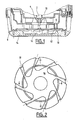
- Figure 3 shows a sectional view of the bottom of a pump according to the invention; we recognizes in the figure the strainer 8, with the pipe 12, the discharge chamber 6, the suction ports 20, and the part 14 which defines the nozzles.
- the strainer presents in its underside a blind hole 22, which is in a symmetrical position of the line 12 relative to the axis of rotation of the pump.
- the lower opening of the line 12 defines an opening under the strainer, for the fluid coming from the delivery chamber.
- the pump has a part 14 which defines the nozzles. As show Figures 4 and 5, this part has a central chamber 16, in which open the nozzles 18. There are provided screw holes 24, for fixing part 14 under the strainer.
- the part also has a stud 26; this nipple has a shape and size that allows it to close the pipe 12.
- the nipple is cylindrical, and has a diameter which is equal to the diameter inside of line 12, apart from assembly clearances. This nipple is positioned by relative to the screw holes so that the part 14 can be mounted under the strainer, with the stud 26 in the pipe 12.
- the part 14 has an inclined portion 28 which returns the fluid arriving from the pipe to the central chamber 16 of the part 14.
- the stud 26 is substantially symmetrical with this inclined part 28 relative to the axis of rotation of the pump.
- the pump of the invention works, from the point of view of suction and delivery, like the pumps of the prior art.
- the pipe 12 opens above the inclined part 28, and the fluid which leaves the pipe is directed towards the central chamber 16, then towards the nozzles. This ensures cleaning of the bottom of the sump around the pump.
- the invention allows simple assembly of the part 14 in the factory, in the first position or in the second position. It is possible for the manufacturer to use a single piece to provide pumps with or without the sump cleaning function. It is also possible, for the user or the installer, to easily dismantle part 14, to turn it over and change the features of the pump.
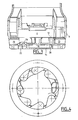
- Figure 6 shows a bottom view of a pump according to the invention. We recognize in the figure the suction ports of the pump, and the nozzles for ejection of the fluid.
- the present invention is not limited to the embodiments described by way of example; thus, it is clear that the position of the shutter nipple can vary, and is not necessarily symmetrical to the inclined part. We might not turn the workpiece only a quarter turn, instead of turning it a half turn. In fact, in a rotation leaving the fixing means globally invariant, the stud is the image of the inclined part (or vice versa), so that you can arrange the nipple or the inclined part opposite the lower opening of the pipe 12.
- Part 14 could have several nipples, allowing partially or completely block line 12; such a configuration would allow for example to regulate the rate of ejection of the fluid by the nozzles, during the mounting of the part. With mounting by four screws, as in the example of figures, four mounting positions are possible, and four levels can be provided flow control.
- the shape of the nipple given by way of example in the figures can vary. By nipple is meant any shape capable of blocking the opening defined by the driving 12.
- the invention is also not limited to fixing the part with screws. We can therefore use other forms of mounting the part. This in the modes of realization of the figures is fixed on the strainer: it could also be fixed on other parts of the pump. In all cases, the part is under the strainer if the fluid ejection opening is provided under the strainer.
Landscapes
- Engineering & Computer Science (AREA)
- Mechanical Engineering (AREA)
- General Engineering & Computer Science (AREA)
- Details Of Reciprocating Pumps (AREA)
- Structures Of Non-Positive Displacement Pumps (AREA)
- Cleaning By Liquid Or Steam (AREA)
Applications Claiming Priority (2)
| Application Number | Priority Date | Filing Date | Title |
|---|---|---|---|
| FR9912706 | 1999-10-12 | ||
| FR9912706A FR2799513B1 (fr) | 1999-10-12 | 1999-10-12 | Pompe domestique autonettoyante |
Publications (2)
| Publication Number | Publication Date |
|---|---|
| EP1092875A1 true EP1092875A1 (de) | 2001-04-18 |
| EP1092875B1 EP1092875B1 (de) | 2005-11-30 |
Family
ID=9550829
Family Applications (1)
| Application Number | Title | Priority Date | Filing Date |
|---|---|---|---|
| EP20000402806 Expired - Lifetime EP1092875B1 (de) | 1999-10-12 | 2000-10-11 | Selbstreinigende Haushaltspumpe |
Country Status (3)
| Country | Link |
|---|---|
| EP (1) | EP1092875B1 (de) |
| DE (1) | DE60024391T2 (de) |
| FR (1) | FR2799513B1 (de) |
Citations (4)
| Publication number | Priority date | Publication date | Assignee | Title |
|---|---|---|---|---|
| DE805007C (de) | 1950-01-31 | 1951-05-04 | Rudolf Flender | Zentrifugalpumpe zum Ruehren und Foerdern von Jauche und anderen schlammigen Fluessigkeiten |
| DE849957C (de) | 1949-01-25 | 1952-09-18 | Ostfriesische Maschinen Und Ge | Vertikal-Kreiselpumpe mit Ruehreinrichtung und Pumpenspuelung zum Foerdern von Dickstoffen, Jauche u. dgl. |
| DE9000953U1 (de) * | 1990-01-29 | 1990-04-05 | Manteuffel, Hans J. M., 4000 Düsseldorf | Tauchpumpe |
| EP0440046A1 (de) | 1990-01-29 | 1991-08-07 | Heinz Zimmermann | Tauchpumpe |
-
1999
- 1999-10-12 FR FR9912706A patent/FR2799513B1/fr not_active Expired - Fee Related
-
2000
- 2000-10-11 EP EP20000402806 patent/EP1092875B1/de not_active Expired - Lifetime
- 2000-10-11 DE DE2000624391 patent/DE60024391T2/de not_active Expired - Lifetime
Patent Citations (4)
| Publication number | Priority date | Publication date | Assignee | Title |
|---|---|---|---|---|
| DE849957C (de) | 1949-01-25 | 1952-09-18 | Ostfriesische Maschinen Und Ge | Vertikal-Kreiselpumpe mit Ruehreinrichtung und Pumpenspuelung zum Foerdern von Dickstoffen, Jauche u. dgl. |
| DE805007C (de) | 1950-01-31 | 1951-05-04 | Rudolf Flender | Zentrifugalpumpe zum Ruehren und Foerdern von Jauche und anderen schlammigen Fluessigkeiten |
| DE9000953U1 (de) * | 1990-01-29 | 1990-04-05 | Manteuffel, Hans J. M., 4000 Düsseldorf | Tauchpumpe |
| EP0440046A1 (de) | 1990-01-29 | 1991-08-07 | Heinz Zimmermann | Tauchpumpe |
Also Published As
| Publication number | Publication date |
|---|---|
| FR2799513A1 (fr) | 2001-04-13 |
| FR2799513B1 (fr) | 2002-01-18 |
| EP1092875B1 (de) | 2005-11-30 |
| DE60024391D1 (de) | 2006-01-05 |
| DE60024391T2 (de) | 2006-08-17 |
Similar Documents
| Publication | Publication Date | Title |
|---|---|---|
| FR2671845A1 (fr) | Bec fabrique de robinet. | |
| FR2567752A3 (fr) | Gicleur pour hydro-massage | |
| EP1034337B1 (de) | Wasserabführungseinrichtung | |
| FR2523430A3 (fr) | Lave-vaisselle avec pompe de circulation realisee sous la forme d'une pompe centrifuge | |
| EP1092875B1 (de) | Selbstreinigende Haushaltspumpe | |
| FR2609482A1 (fr) | Appareil de robinetterie pour le remplissage d'une baignoire | |
| EP0689630B1 (de) | Selbstreinigende toilettenbrille | |
| FR2642104A1 (fr) | Dispositif de regulation de debit pour circuit de nettoyage d'un bassin, en particulier d'une piscine | |
| FR2693219A1 (fr) | Installation de water-closet avec système d'aspiration des odeurs. | |
| FR2800260A1 (fr) | Installation sanitaire et dispositif de vidande pour une telle installation | |
| WO2003062561A1 (fr) | Procede de circulation et nettoyage de l'eau de piscines, implantation d'un systeme pour la mise en oeuvre du procede et multiplicateur de debit adapte | |
| FR2762361A1 (fr) | Boitier en forme de pot destine a recevoir une pompe de transfert de liquide | |
| KR200317941Y1 (ko) | 회전식 물걸레 청소기 | |
| FR2578879A1 (fr) | Robinetterie pour baignoire | |
| FR3121693A1 (fr) | Dispositif d’équipement sanitaire pour cuvette de toilette | |
| EP0561689B1 (de) | Kreiselpumpen | |
| EP1267108B1 (de) | Mischventil, insbesondere für einen Heizkessel | |
| EP0484213B1 (de) | Sanitärapparat für Zwangabfluss von Abwasser | |
| KR200153299Y1 (ko) | 수도관 동파방지용 퇴수밸브 | |
| JP4356425B2 (ja) | 衛生洗浄装置 | |
| EP2142316B1 (de) | Kammer zum waschen des ausgiessablaufs eines milchlagerungs- und -kühlbehälters | |
| CA1292103C (fr) | Cuvettes de cabinets d'aisance | |
| CN116195940B (zh) | 一种清洗机 | |
| KR0131506Y1 (ko) | 글로브밸브 | |
| EP0113278B1 (de) | Flüssigkeitspumpenvorrichtung, insbesondere für die Brennstoffzufuhr eines Brenners |
Legal Events
| Date | Code | Title | Description |
|---|---|---|---|
| PUAI | Public reference made under article 153(3) epc to a published international application that has entered the european phase |
Free format text: ORIGINAL CODE: 0009012 |
|
| AK | Designated contracting states |
Kind code of ref document: A1 Designated state(s): DE FR GB IT |
|
| AX | Request for extension of the european patent |
Free format text: AL;LT;LV;MK;RO;SI |
|
| 17P | Request for examination filed |
Effective date: 20010924 |
|
| AKX | Designation fees paid |
Free format text: DE FR GB IT |
|
| GRAP | Despatch of communication of intention to grant a patent |
Free format text: ORIGINAL CODE: EPIDOSNIGR1 |
|
| GRAS | Grant fee paid |
Free format text: ORIGINAL CODE: EPIDOSNIGR3 |
|
| GRAA | (expected) grant |
Free format text: ORIGINAL CODE: 0009210 |
|
| AK | Designated contracting states |
Kind code of ref document: B1 Designated state(s): DE FR GB IT |
|
| PG25 | Lapsed in a contracting state [announced via postgrant information from national office to epo] |
Ref country code: IT Free format text: LAPSE BECAUSE OF FAILURE TO SUBMIT A TRANSLATION OF THE DESCRIPTION OR TO PAY THE FEE WITHIN THE PRESCRIBED TIME-LIMIT;WARNING: LAPSES OF ITALIAN PATENTS WITH EFFECTIVE DATE BEFORE 2007 MAY HAVE OCCURRED AT ANY TIME BEFORE 2007. THE CORRECT EFFECTIVE DATE MAY BE DIFFERENT FROM THE ONE RECORDED. Effective date: 20051130 |
|
| REG | Reference to a national code |
Ref country code: GB Ref legal event code: FG4D Free format text: NOT ENGLISH |
|
| REF | Corresponds to: |
Ref document number: 60024391 Country of ref document: DE Date of ref document: 20060105 Kind code of ref document: P |
|
| GBT | Gb: translation of ep patent filed (gb section 77(6)(a)/1977) |
Effective date: 20060224 |
|
| PLBE | No opposition filed within time limit |
Free format text: ORIGINAL CODE: 0009261 |
|
| STAA | Information on the status of an ep patent application or granted ep patent |
Free format text: STATUS: NO OPPOSITION FILED WITHIN TIME LIMIT |
|
| 26N | No opposition filed |
Effective date: 20060831 |
|
| REG | Reference to a national code |
Ref country code: FR Ref legal event code: PLFP Year of fee payment: 16 |
|
| PGFP | Annual fee paid to national office [announced via postgrant information from national office to epo] |
Ref country code: IT Payment date: 20151026 Year of fee payment: 16 Ref country code: DE Payment date: 20151006 Year of fee payment: 16 Ref country code: GB Payment date: 20151007 Year of fee payment: 16 |
|
| PGFP | Annual fee paid to national office [announced via postgrant information from national office to epo] |
Ref country code: FR Payment date: 20151002 Year of fee payment: 16 |
|
| REG | Reference to a national code |
Ref country code: DE Ref legal event code: R119 Ref document number: 60024391 Country of ref document: DE |
|
| GBPC | Gb: european patent ceased through non-payment of renewal fee |
Effective date: 20161011 |
|
| REG | Reference to a national code |
Ref country code: FR Ref legal event code: ST Effective date: 20170630 |
|
| PG25 | Lapsed in a contracting state [announced via postgrant information from national office to epo] |
Ref country code: DE Free format text: LAPSE BECAUSE OF NON-PAYMENT OF DUE FEES Effective date: 20170503 Ref country code: GB Free format text: LAPSE BECAUSE OF NON-PAYMENT OF DUE FEES Effective date: 20161011 Ref country code: FR Free format text: LAPSE BECAUSE OF NON-PAYMENT OF DUE FEES Effective date: 20161102 |
|
| PG25 | Lapsed in a contracting state [announced via postgrant information from national office to epo] |
Ref country code: IT Free format text: LAPSE BECAUSE OF NON-PAYMENT OF DUE FEES Effective date: 20161011 |