EP1092921A2 - Vorrichtung zum Schälen eines aufgeweiteten Kesselrohrendes - Google Patents
Vorrichtung zum Schälen eines aufgeweiteten Kesselrohrendes Download PDFInfo
- Publication number
- EP1092921A2 EP1092921A2 EP00203278A EP00203278A EP1092921A2 EP 1092921 A2 EP1092921 A2 EP 1092921A2 EP 00203278 A EP00203278 A EP 00203278A EP 00203278 A EP00203278 A EP 00203278A EP 1092921 A2 EP1092921 A2 EP 1092921A2
- Authority
- EP
- European Patent Office
- Prior art keywords
- subassembly
- peeler
- tool
- clamp
- boiler tube
- Prior art date
- Legal status (The legal status is an assumption and is not a legal conclusion. Google has not performed a legal analysis and makes no representation as to the accuracy of the status listed.)
- Withdrawn
Links
- 239000002184 metal Substances 0.000 claims abstract description 16
- 230000000717 retained effect Effects 0.000 claims abstract description 9
- 239000012530 fluid Substances 0.000 claims abstract description 8
- 230000014759 maintenance of location Effects 0.000 claims abstract 3
- 238000005452 bending Methods 0.000 claims description 4
- 238000010008 shearing Methods 0.000 claims description 4
- 230000000694 effects Effects 0.000 claims description 2
- 238000006073 displacement reaction Methods 0.000 claims 1
- 230000006835 compression Effects 0.000 description 2
- 238000007906 compression Methods 0.000 description 2
- 229910001315 Tool steel Inorganic materials 0.000 description 1
- 229910045601 alloy Inorganic materials 0.000 description 1
- 239000000956 alloy Substances 0.000 description 1
- 238000002485 combustion reaction Methods 0.000 description 1
- 238000010276 construction Methods 0.000 description 1
- 238000000605 extraction Methods 0.000 description 1
- 239000000446 fuel Substances 0.000 description 1
- 238000010438 heat treatment Methods 0.000 description 1
- 238000003780 insertion Methods 0.000 description 1
- 230000037431 insertion Effects 0.000 description 1
- 238000012423 maintenance Methods 0.000 description 1
- 239000000463 material Substances 0.000 description 1
- 230000002093 peripheral effect Effects 0.000 description 1
- 230000002441 reversible effect Effects 0.000 description 1
- XLYOFNOQVPJJNP-UHFFFAOYSA-N water Substances O XLYOFNOQVPJJNP-UHFFFAOYSA-N 0.000 description 1
Images



Classifications
-
- B—PERFORMING OPERATIONS; TRANSPORTING
- B23—MACHINE TOOLS; METAL-WORKING NOT OTHERWISE PROVIDED FOR
- B23D—PLANING; SLOTTING; SHEARING; BROACHING; SAWING; FILING; SCRAPING; LIKE OPERATIONS FOR WORKING METAL BY REMOVING MATERIAL, NOT OTHERWISE PROVIDED FOR
- B23D21/00—Machines or devices for shearing or cutting tubes
- B23D21/02—Machines or devices for shearing or cutting tubes otherwise than in a plane perpendicular to the axis of the tube, e.g. for making mitred cuts, for making bicycle frames
-
- B—PERFORMING OPERATIONS; TRANSPORTING
- B23—MACHINE TOOLS; METAL-WORKING NOT OTHERWISE PROVIDED FOR
- B23B—TURNING; BORING
- B23B31/00—Chucks; Expansion mandrels; Adaptations thereof for remote control
- B23B31/02—Chucks
- B23B31/10—Chucks characterised by the retaining or gripping devices or their immediate operating means
- B23B31/12—Chucks with simultaneously-acting jaws, whether or not also individually adjustable
- B23B31/18—Chucks with simultaneously-acting jaws, whether or not also individually adjustable pivotally movable in planes containing the axis of the chuck
- B23B31/185—Chucks with simultaneously-acting jaws, whether or not also individually adjustable pivotally movable in planes containing the axis of the chuck moving first parallel to the axis then pivotally in planes containing the axis of the chuck
-
- F—MECHANICAL ENGINEERING; LIGHTING; HEATING; WEAPONS; BLASTING
- F22—STEAM GENERATION
- F22B—METHODS OF STEAM GENERATION; STEAM BOILERS
- F22B37/00—Component parts or details of steam boilers
- F22B37/02—Component parts or details of steam boilers applicable to more than one kind or type of steam boiler
- F22B37/58—Removing tubes from headers or drums; Extracting tools
-
- Y—GENERAL TAGGING OF NEW TECHNOLOGICAL DEVELOPMENTS; GENERAL TAGGING OF CROSS-SECTIONAL TECHNOLOGIES SPANNING OVER SEVERAL SECTIONS OF THE IPC; TECHNICAL SUBJECTS COVERED BY FORMER USPC CROSS-REFERENCE ART COLLECTIONS [XRACs] AND DIGESTS
- Y10—TECHNICAL SUBJECTS COVERED BY FORMER USPC
- Y10T—TECHNICAL SUBJECTS COVERED BY FORMER US CLASSIFICATION
- Y10T29/00—Metal working
- Y10T29/49—Method of mechanical manufacture
- Y10T29/4935—Heat exchanger or boiler making
- Y10T29/49352—Repairing, converting, servicing or salvaging
-
- Y—GENERAL TAGGING OF NEW TECHNOLOGICAL DEVELOPMENTS; GENERAL TAGGING OF CROSS-SECTIONAL TECHNOLOGIES SPANNING OVER SEVERAL SECTIONS OF THE IPC; TECHNICAL SUBJECTS COVERED BY FORMER USPC CROSS-REFERENCE ART COLLECTIONS [XRACs] AND DIGESTS
- Y10—TECHNICAL SUBJECTS COVERED BY FORMER USPC
- Y10T—TECHNICAL SUBJECTS COVERED BY FORMER US CLASSIFICATION
- Y10T29/00—Metal working
- Y10T29/51—Plural diverse manufacturing apparatus including means for metal shaping or assembling
- Y10T29/5199—Work on tubes
-
- Y—GENERAL TAGGING OF NEW TECHNOLOGICAL DEVELOPMENTS; GENERAL TAGGING OF CROSS-SECTIONAL TECHNOLOGIES SPANNING OVER SEVERAL SECTIONS OF THE IPC; TECHNICAL SUBJECTS COVERED BY FORMER USPC CROSS-REFERENCE ART COLLECTIONS [XRACs] AND DIGESTS
- Y10—TECHNICAL SUBJECTS COVERED BY FORMER USPC
- Y10T—TECHNICAL SUBJECTS COVERED BY FORMER US CLASSIFICATION
- Y10T29/00—Metal working
- Y10T29/53—Means to assemble or disassemble
- Y10T29/53113—Heat exchanger
-
- Y—GENERAL TAGGING OF NEW TECHNOLOGICAL DEVELOPMENTS; GENERAL TAGGING OF CROSS-SECTIONAL TECHNOLOGIES SPANNING OVER SEVERAL SECTIONS OF THE IPC; TECHNICAL SUBJECTS COVERED BY FORMER USPC CROSS-REFERENCE ART COLLECTIONS [XRACs] AND DIGESTS
- Y10—TECHNICAL SUBJECTS COVERED BY FORMER USPC
- Y10T—TECHNICAL SUBJECTS COVERED BY FORMER US CLASSIFICATION
- Y10T29/00—Metal working
- Y10T29/53—Means to assemble or disassemble
- Y10T29/53113—Heat exchanger
- Y10T29/53122—Heat exchanger including deforming means
Definitions
- This invention pertains generally to power boilers, and specifically concerns apparatus that is particularly useful in connection with the maintenance removal of selected boiler tubes from being installed in a boiler drum wall as for subsequent replacement.
- the present invention is basically an assembly comprised of: a threaded body subassembly; a clamp subassembly carried by the threaded body subassembly and adapted, when actuated, to clamp the tool assembly to the interior wall of the partially-gapped boiler tube-end that is to have its remaining gap metal removed by a "peeling" operation; a conventional pressurized-fluid actuator subassembly also carried by the tool threaded body subassembly and having an actuator cylinder and co-operating actuator piston rod; and a tool peeler blade subassembly connected to and reciprocated by the actuator subassembly piston rod.
- the invention tool assembly is operated to sequentially clamp the assembly to the interior wall surface of the co-operating boiler tube end segment, engage and continuously bend and shear the between-gaps metal in the wall-retained boiler tube end-segment throughout the end-segment length during a tool assembly power stroke, retract the assembly peeler blade element, and release the tool assembly from clamped engagement with the boiler tube end-segment wall surface.
- the tube retained end-segment is then in a condition readied for subsequent tube diametric compression and withdrawal.
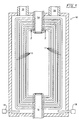
- FIG 1 schematically illustrates a power boiler 10 having multiple conventional boiler water-tubes 12 installed with their upper and lower flared ends co-operating with the walls of boiler steam and mud drums 14 and 16 , respectively.
- Burners 18 are typically fired by a carbonaceous fuel, and the resulting effluent gasses of combustion, following heat extraction for water and steam heating purposes, are exhausted from within power boiler 10 through chimney connections 20 .
- it is necessary from time to time to remove and replace one or more of individual boiler tubes 12 from within power boiler 10 and such is basically accomplished by selected tubes first being cut at their ends adjacent the exterior wall metal of drums 14 and 16 for removal.
- the boiler tube flared-end segment peeler tool 100 of the present invention pertains generally to the removal of the remaining tube flared-end segments 13 that are initially retained in the steam and mud drum peripheral walls and, as illustrated in Figure 2, such tool is basically utilized from a position within or interior of the applicable boiler drum largely as a matter of convenience.
- FIG. 3 of the drawings I illustrate a preferred embodiment of the tool assembly of the present invention, and such is designated 100 and is basically comprised of a tool body subassembly 102 , a clamp subassembly 104 which co-operates with the body subassembly and which functions to securely clamp tool assembly 100 in a proper mounted position with a boiler tube end-segment during tool utilization, a peeler blade subassembly 106 , and a conventional pressurized-fluid actuator subassembly 108 , illustrated in a retracted operating condition, which is mounted on body subassembly 102 and which is connected to peeler blade subassembly 106 in powering relation.
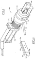
- Figure 4 illustrates tool assembly 100 in perspective.
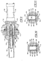
- Figures 5 and 6 illustrate tool body subassembly 102 as being comprised of a sleeve-like threaded body element 110 , a support end plate element 112 securely attached to element 110 by threaded fasteners 116 , and a stop end plate 114 also securely attached to element 110 by threaded fasteners designated 116 .
- body element 110 includes a pair of integral opposite elongated slots 118 (only one of which is shown in Figure 4) that accommodate longitudinal movement of a pair of clamp pivots which are included in clamp subassembly 104 .
- Clamp subassembly is basically comprised a pair of toothed, spaced-apart, and pivoted clamp upper expansion jaw elements 120 , a pair of toothed, spaced-apart, and pivoted clamp lower expansion jaw elements 122 (see Figures 9 and 10), and a pair of wedge elements 124 which pivotally expand the jaw element pairs into engagement with the interior surface of a boiler tube end-segment when retracted. Pairs of transverse pivots 126 are carried by stop end plate 114 and each co-operates with an elongated slot 128 provided in each jaw element 120 or 122 .
- Clamping subassembly 104 also includes a removable handle 130 (see Figure 4) that is used to manually turn threaded clamp sleeve 132 relative to co-operating threaded tool body element 110 to effect retraction and advancement of wedge element 124 in connection with clamping and releasing tool assembly 100 from engagement with boiler tube-end segment 12 prior to commencing and after completing the "peeling" operation that is to be performed.
- a slip ring 134 that is longitudinally but not rotationally secured to threaded clamp sleeve 132 by retainer ring 136 , carries transverse pin element 138 to complete the handle-to-wedge element connection.
- Such pin element reciprocates within longitudinal slot 118 provided in tool threaded body element 110 .
- each expansion clamp jaw element 120 and 122 is preferably provided with a projection tab element 140 that functions to disengage that element from clamping contact with a co-operating boiler tube-end segment when wedge elements 124 are advanced to their initial operating position ( Figure 7) when threaded clamp sleeve 132 contacts projection tabs 140 and causes rotational tool-releasing movement of clamp expansion jaws 120 and 122 about transverse pivots 126 ,
- Tool peeler subassembly 106 includes a peeler blade element 150 that is secured in a channel member 152 by threaded fasteners 154 (see Figure 9) and that is connected to and powered by piston rod element 170 of pressurized-fluid actuator subassembly 108 .
- the upper extreme of each vertical leg of channel member 152 is rounded in cross-section, abuts the interior surface of tube segment 13 during tool assembly peeling operation, and functions as a shear shoulder.
- See Figure 12 for a perspective illustration and additional details of the construction of invention blade element 150 , which blade element, like channel member 152 , is preferably fabricated of a conventional hardened cutting tool steel alloy.
- Channel member 152 has a pivoted end closure 156 that is retained in a closed position by conventional detents (not shown) and functions to retain within tool assembly 100 the curled remaining gap metal that is peeled from tube-end segment 13 by tool operation. Also, and as best illustrated in Figure 4, each vertical wall of channel member 152 is preferably provided with an integral rib element 158 that co-operates with an integral groove formed in the adjacent wedge element 124 .
- Conventional reversible pressurized-fluid actuator assembly 108 is preferably removably mounted on support end plate element 112 and is basically comprised of, in addition to piston rod element 170 , an actuator cylinder element 172 that internally contains an actuator piston joined to piston rod element 170 , and actuator reversing controls 174 . Not shown in the drawings are details of conventional source of pressurized operating fluid for actuator subassembly 108 and necessary to power tool assembly 100 .
- Figure 12 is provided in the drawings to more clearly illustrate important features of peeler tool element 150 .
- the illustrated tool lip surface area 180 whose upper edge 182 is positioned a fixed distance above integral paired shoulders 184 and 186 (see Figure 11) that assures that any part of tool lip 180 will not contact boiler drum wall metal when such shoulders are in contact with the interior surface of boiler tube flared-end segment 13 .
- tool lip 180 is joined to a contiguous curved end curling surface 188 that, when engaged with the down-turned gap end metal 13a of tube segment 13 and advanced toward the tool assembly peeler actuation stroke end, causes that down-turned gap metal to be further peeled from tube end segment 13 as best shown in Figure 6.
- the initial step is to insert the assembly forward end into the drum-retained boiler tube end-segment until the vertical face of stop end plate element 114 contacts the tube segment flared end.
- clamp subassembly threaded sleeve 132 is manually rotated to move wedge elements 124 in an aft direction until clamp expansion jaw elements 120 and 122 are engaged with the tube segment wall interior surface as shown in Figure 8 to securely clamp or lock the tool assembly in its operating position.
- the pressurized-fluid actuator subassembly 108 is then operated to cause peeler blade element 150 to be moved in a forward direction to first engage down-turned gap metal 13a at the retained tube flared end ( Figure 5) and progressively peel the remaining gap metal by combined bending and shearing until that gap metal is separated completely from the tube-end segment ( Figure 6). Afterwards peeler blade element 150 is retracted to its initial position. To accomplish this threaded clamp sleeve 132 is turned in an opposite direction to engage tabs 140 of blades ( 120 and 122 ) ( Figures 7 and 8) to rotate clamp expansion jaw elements 120 and 122 out of engagement with the tube-end segment interior surface thus freeing tool assembly 100 from being retained in a clamped condition. Lastly assembly 100 is withdrawn from engagement with boiler tube flared-end segment 13 to ready such segment for subsequent tube removal steps of segment diametric compression and longitudinal withdrawal from within the boiler drum wall.
Landscapes
- Engineering & Computer Science (AREA)
- Mechanical Engineering (AREA)
- Physics & Mathematics (AREA)
- Thermal Sciences (AREA)
- General Engineering & Computer Science (AREA)
- Hand Tools For Fitting Together And Separating, Or Other Hand Tools (AREA)
- Branch Pipes, Bends, And The Like (AREA)
Applications Claiming Priority (2)
| Application Number | Priority Date | Filing Date | Title |
|---|---|---|---|
| US416692 | 1999-10-12 | ||
| US09/416,692 US6209181B1 (en) | 1999-10-12 | 1999-10-12 | Boiler tube flare-end segment peeler tool |
Publications (2)
| Publication Number | Publication Date |
|---|---|
| EP1092921A2 true EP1092921A2 (de) | 2001-04-18 |
| EP1092921A3 EP1092921A3 (de) | 2001-09-12 |
Family
ID=23650926
Family Applications (1)
| Application Number | Title | Priority Date | Filing Date |
|---|---|---|---|
| EP00203278A Withdrawn EP1092921A3 (de) | 1999-10-12 | 2000-09-21 | Vorrichtung zum Schälen eines aufgeweiteten Kesselrohrendes |
Country Status (3)
| Country | Link |
|---|---|
| US (1) | US6209181B1 (de) |
| EP (1) | EP1092921A3 (de) |
| CA (1) | CA2322725C (de) |
Families Citing this family (6)
| Publication number | Priority date | Publication date | Assignee | Title |
|---|---|---|---|---|
| US6430790B1 (en) * | 2000-04-26 | 2002-08-13 | Advanced Cutting Technologies, Ltd. | Boiler tube flared-end segment peeler tool |
| US7305756B2 (en) * | 2004-04-22 | 2007-12-11 | Barcock & Wilcox Canada Ltd. | Tube extracting device |
| US7194800B2 (en) * | 2004-06-07 | 2007-03-27 | Babcick & Wilcox Canada, Ltd. | Internal tube extracting device with a cylindrical collapsing wedge |
| US7146716B2 (en) * | 2004-06-08 | 2006-12-12 | Babcock & Wilcox Canada Ltd. | External tube extraction device with a cylindrical collapsing wedge |
| US7168143B2 (en) * | 2004-06-30 | 2007-01-30 | Babcock & Wilcox Canada Ltd. | External tube deforming extraction device |
| CN115026616B (zh) * | 2022-06-23 | 2023-05-09 | 福建省泷澄建设集团有限公司 | 一种排水管安装加工用坡口机 |
Citations (1)
| Publication number | Priority date | Publication date | Assignee | Title |
|---|---|---|---|---|
| US5893209A (en) | 1997-09-22 | 1999-04-13 | Weeks; Bruce V. | Apparatus for effecting boiler tube removal |
Family Cites Families (9)
| Publication number | Priority date | Publication date | Assignee | Title |
|---|---|---|---|---|
| US3729806A (en) * | 1968-09-06 | 1973-05-01 | Carrier Corp | Method for tube removal |
| US3857158A (en) * | 1972-12-19 | 1974-12-31 | D Costello | Method and apparatus for removing condenser tubes from surface condensers |
| US3835520A (en) * | 1973-09-10 | 1974-09-17 | Harris R | Tube pulling apparatus |
| US4967468A (en) * | 1986-10-27 | 1990-11-06 | Torque And Tension Equipment Inc. | Apparatus for fixing boiler tubes during replacement of same |
| FR2666879B1 (fr) * | 1990-09-19 | 1993-03-19 | Framatome Sa | Procede de remplacement d'un tube d'un echangeur de chaleur a tubes droits et utilisation de ce procede. |
| JP2966262B2 (ja) * | 1993-12-07 | 1999-10-25 | 株式会社ニチリン | チューブの剥離方法および剥離器 |
| DE19609958C2 (de) * | 1996-03-14 | 2000-06-15 | Dillinger Stahlbau | Verfahren zur Reparatur von Wärmetauscherrohren im Inneren von geschlossenen Röhrenapparaten |
| US5826334A (en) * | 1997-03-10 | 1998-10-27 | Advanced Cutting Technologies, Inc. | Boiler tube removal method |
| EP1096199A2 (de) * | 1999-10-27 | 2001-05-02 | Advanced Cutting Technologies, Ltd. | Methode zum Entfernen eines Kesselrohres |
-
1999
- 1999-10-12 US US09/416,692 patent/US6209181B1/en not_active Expired - Fee Related
-
2000
- 2000-09-21 EP EP00203278A patent/EP1092921A3/de not_active Withdrawn
- 2000-10-10 CA CA002322725A patent/CA2322725C/en not_active Expired - Fee Related
Patent Citations (1)
| Publication number | Priority date | Publication date | Assignee | Title |
|---|---|---|---|---|
| US5893209A (en) | 1997-09-22 | 1999-04-13 | Weeks; Bruce V. | Apparatus for effecting boiler tube removal |
Also Published As
| Publication number | Publication date |
|---|---|
| CA2322725C (en) | 2007-01-09 |
| CA2322725A1 (en) | 2001-04-12 |
| EP1092921A3 (de) | 2001-09-12 |
| US6209181B1 (en) | 2001-04-03 |
Similar Documents
| Publication | Publication Date | Title |
|---|---|---|
| US6209181B1 (en) | Boiler tube flare-end segment peeler tool | |
| US6971283B2 (en) | Jaw insert for gripping a cylindrical member and method of manufacture | |
| KR930006782B1 (ko) | 튜브 풀링 장치 | |
| US5743680A (en) | Metal removing tool, in particular lancing insert | |
| US10085852B2 (en) | Locking grip orthopedic implant extraction tool | |
| US7748297B2 (en) | Cam operated jaw force intensifier for gripping a cylindrical member | |
| EP3865757A1 (de) | Greifer und vorrichtungen zum zustopfen von rohren, öffnungen oder zum anschliessen | |
| US3314320A (en) | Shear pin pliers | |
| US4381105A (en) | Clamp | |
| US8656570B2 (en) | Fastener extraction tool | |
| JP2004504096A (ja) | 安全ラチェットメカニズム | |
| US4324125A (en) | Auto body clamp | |
| EP1092923A2 (de) | Vorrichtung zum Scheren und Biegen eines Kesselrohrsegmentes | |
| JP2000052302A (ja) | チェ―ンソ―のガイドバ― | |
| NO335557B1 (no) | Anordning, kjevesammenstilling og fremgangsmåte til bruk ved griping av et sylindrisk element. | |
| CA2322722C (en) | Boiler tube flared-end compression tool | |
| US6430790B1 (en) | Boiler tube flared-end segment peeler tool | |
| US4355450A (en) | Method of operating a tube extracting mechanism | |
| US2564585A (en) | Pliers or wrench with automatic adjusting and locking means | |
| US4315424A (en) | Vehicle body clamp | |
| EP0005463A1 (de) | Verfahren und Vorrichtung zum Ausziehen von Rohren | |
| JP2001058134A (ja) | 高信頼性プレ−ト切断特性を有する大型解体剪断機 | |
| CA2340809A1 (en) | Ring cutting tool | |
| US4246699A (en) | Nut cutting or nut breaking tool | |
| US1273831A (en) | Boiler-tube extractor. |
Legal Events
| Date | Code | Title | Description |
|---|---|---|---|
| PUAI | Public reference made under article 153(3) epc to a published international application that has entered the european phase |
Free format text: ORIGINAL CODE: 0009012 |
|
| AK | Designated contracting states |
Kind code of ref document: A2 Designated state(s): AT BE CH CY DE DK ES FI FR GB GR IE IT LI LU MC NL PT SE Kind code of ref document: A2 Designated state(s): DE ES FR GB IT SE |
|
| AX | Request for extension of the european patent |
Free format text: AL;LT;LV;MK;RO;SI |
|
| PUAL | Search report despatched |
Free format text: ORIGINAL CODE: 0009013 |
|
| AK | Designated contracting states |
Kind code of ref document: A3 Designated state(s): AT BE CH CY DE DK ES FI FR GB GR IE IT LI LU MC NL PT SE |
|
| AX | Request for extension of the european patent |
Free format text: AL;LT;LV;MK;RO;SI |
|
| RIC1 | Information provided on ipc code assigned before grant |
Free format text: 7F 22B 37/58 A, 7B 23D 21/00 B, 7B 23P 19/02 B |
|
| 17P | Request for examination filed |
Effective date: 20020104 |
|
| AKX | Designation fees paid |
Free format text: DE ES FR GB IT SE |
|
| 17Q | First examination report despatched |
Effective date: 20080411 |
|
| STAA | Information on the status of an ep patent application or granted ep patent |
Free format text: STATUS: THE APPLICATION IS DEEMED TO BE WITHDRAWN |
|
| 18D | Application deemed to be withdrawn |
Effective date: 20080822 |