EP1092923A2 - Dispositif pour cisailler et plier un segment d'un tube de chaudière - Google Patents
Dispositif pour cisailler et plier un segment d'un tube de chaudière Download PDFInfo
- Publication number
- EP1092923A2 EP1092923A2 EP00203280A EP00203280A EP1092923A2 EP 1092923 A2 EP1092923 A2 EP 1092923A2 EP 00203280 A EP00203280 A EP 00203280A EP 00203280 A EP00203280 A EP 00203280A EP 1092923 A2 EP1092923 A2 EP 1092923A2
- Authority
- EP
- European Patent Office
- Prior art keywords
- shear
- boiler tube
- tube segment
- tool
- rotatable
- Prior art date
- Legal status (The legal status is an assumption and is not a legal conclusion. Google has not performed a legal analysis and makes no representation as to the accuracy of the status listed.)
- Withdrawn
Links
- 239000002184 metal Substances 0.000 claims abstract description 17
- 238000005452 bending Methods 0.000 claims description 6
- 239000012530 fluid Substances 0.000 claims description 6
- 238000010008 shearing Methods 0.000 claims description 4
- 238000003780 insertion Methods 0.000 claims description 2
- 230000037431 insertion Effects 0.000 claims description 2
- 230000014759 maintenance of location Effects 0.000 abstract 1
- 238000005520 cutting process Methods 0.000 description 4
- 238000010276 construction Methods 0.000 description 2
- 238000002360 preparation method Methods 0.000 description 2
- 230000000717 retained effect Effects 0.000 description 2
- 230000015572 biosynthetic process Effects 0.000 description 1
- 238000002485 combustion reaction Methods 0.000 description 1
- 230000000694 effects Effects 0.000 description 1
- 238000000605 extraction Methods 0.000 description 1
- 239000000446 fuel Substances 0.000 description 1
- 238000010438 heat treatment Methods 0.000 description 1
- 238000012423 maintenance Methods 0.000 description 1
- 230000002093 peripheral effect Effects 0.000 description 1
- 230000002441 reversible effect Effects 0.000 description 1
- XLYOFNOQVPJJNP-UHFFFAOYSA-N water Substances O XLYOFNOQVPJJNP-UHFFFAOYSA-N 0.000 description 1
Images


Classifications
-
- B—PERFORMING OPERATIONS; TRANSPORTING
- B23—MACHINE TOOLS; METAL-WORKING NOT OTHERWISE PROVIDED FOR
- B23P—METAL-WORKING NOT OTHERWISE PROVIDED FOR; COMBINED OPERATIONS; UNIVERSAL MACHINE TOOLS
- B23P19/00—Machines for simply fitting together or separating metal parts or objects, or metal and non-metal parts, whether or not involving some deformation; Tools or devices therefor so far as not provided for in other classes
- B23P19/02—Machines for simply fitting together or separating metal parts or objects, or metal and non-metal parts, whether or not involving some deformation; Tools or devices therefor so far as not provided for in other classes for connecting objects by press fit or for detaching same
- B23P19/022—Extracting or inserting relatively long parts
-
- B—PERFORMING OPERATIONS; TRANSPORTING
- B23—MACHINE TOOLS; METAL-WORKING NOT OTHERWISE PROVIDED FOR
- B23D—PLANING; SLOTTING; SHEARING; BROACHING; SAWING; FILING; SCRAPING; LIKE OPERATIONS FOR WORKING METAL BY REMOVING MATERIAL, NOT OTHERWISE PROVIDED FOR
- B23D21/00—Machines or devices for shearing or cutting tubes
- B23D21/02—Machines or devices for shearing or cutting tubes otherwise than in a plane perpendicular to the axis of the tube, e.g. for making mitred cuts, for making bicycle frames
-
- F—MECHANICAL ENGINEERING; LIGHTING; HEATING; WEAPONS; BLASTING
- F22—STEAM GENERATION
- F22B—METHODS OF STEAM GENERATION; STEAM BOILERS
- F22B37/00—Component parts or details of steam boilers
- F22B37/02—Component parts or details of steam boilers applicable to more than one kind or type of steam boiler
- F22B37/58—Removing tubes from headers or drums; Extracting tools
-
- Y—GENERAL TAGGING OF NEW TECHNOLOGICAL DEVELOPMENTS; GENERAL TAGGING OF CROSS-SECTIONAL TECHNOLOGIES SPANNING OVER SEVERAL SECTIONS OF THE IPC; TECHNICAL SUBJECTS COVERED BY FORMER USPC CROSS-REFERENCE ART COLLECTIONS [XRACs] AND DIGESTS
- Y10—TECHNICAL SUBJECTS COVERED BY FORMER USPC
- Y10T—TECHNICAL SUBJECTS COVERED BY FORMER US CLASSIFICATION
- Y10T29/00—Metal working
- Y10T29/49—Method of mechanical manufacture
- Y10T29/4935—Heat exchanger or boiler making
- Y10T29/49352—Repairing, converting, servicing or salvaging
-
- Y—GENERAL TAGGING OF NEW TECHNOLOGICAL DEVELOPMENTS; GENERAL TAGGING OF CROSS-SECTIONAL TECHNOLOGIES SPANNING OVER SEVERAL SECTIONS OF THE IPC; TECHNICAL SUBJECTS COVERED BY FORMER USPC CROSS-REFERENCE ART COLLECTIONS [XRACs] AND DIGESTS
- Y10—TECHNICAL SUBJECTS COVERED BY FORMER USPC
- Y10T—TECHNICAL SUBJECTS COVERED BY FORMER US CLASSIFICATION
- Y10T29/00—Metal working
- Y10T29/51—Plural diverse manufacturing apparatus including means for metal shaping or assembling
- Y10T29/5199—Work on tubes
-
- Y—GENERAL TAGGING OF NEW TECHNOLOGICAL DEVELOPMENTS; GENERAL TAGGING OF CROSS-SECTIONAL TECHNOLOGIES SPANNING OVER SEVERAL SECTIONS OF THE IPC; TECHNICAL SUBJECTS COVERED BY FORMER USPC CROSS-REFERENCE ART COLLECTIONS [XRACs] AND DIGESTS
- Y10—TECHNICAL SUBJECTS COVERED BY FORMER USPC
- Y10T—TECHNICAL SUBJECTS COVERED BY FORMER US CLASSIFICATION
- Y10T29/00—Metal working
- Y10T29/53—Means to assemble or disassemble
- Y10T29/53113—Heat exchanger
-
- Y—GENERAL TAGGING OF NEW TECHNOLOGICAL DEVELOPMENTS; GENERAL TAGGING OF CROSS-SECTIONAL TECHNOLOGIES SPANNING OVER SEVERAL SECTIONS OF THE IPC; TECHNICAL SUBJECTS COVERED BY FORMER USPC CROSS-REFERENCE ART COLLECTIONS [XRACs] AND DIGESTS
- Y10—TECHNICAL SUBJECTS COVERED BY FORMER USPC
- Y10T—TECHNICAL SUBJECTS COVERED BY FORMER US CLASSIFICATION
- Y10T29/00—Metal working
- Y10T29/53—Means to assemble or disassemble
- Y10T29/53113—Heat exchanger
- Y10T29/53122—Heat exchanger including deforming means
Definitions
- This invention pertains generally to power boilers, and specifically concerns apparatus that is particularly useful in connection with the maintenance removal of selected installed boiler tubes for subsequent replacement
- the present invention is basically comprised of a tool head subassembly provided with a rigid frame, an anvil and co-operating shear blade that is pivotally carried by the frame and engaged with a boiler tube flared end, a reciprocating cam that causes pivoting of the tool assembly shear blade element, and with a reversible, pressurized fluid actuator subassembly that is supported by the tool head frame and that causes reciprocating movement of the tool head cam element.
- Operation of the actuator subassembly in a positive direction following insertion of the tool head anvil in a cut boiler tube flared-end and engagement of the tool shear blade with the boiler tube end segment flare, causes the shear blade to be rotated to double shear and downwardly bend a portion of the lip of the tube flare that ultimately comprises an extension of the desired tube end segment longitudinal gap.
- the tool may then be conveniently removed from engagement with the boiler tube end segment by simple longitudinal rotation, and the reciprocating cam retracted in preparation for next use of the tool.
- FIG 1 schematically illustrates a power boiler 10 having multiple conventional boiler water-tubes 12 installed with their upper and lower flared ends co-operating with boiler steam and mud drums 14 and 16 , respectively.
- Burners 18 are typically fired by a carbonaceous fuel, and the resulting effluent gasses of combustion, following heat extraction for water and steam heating purposes, are exhausted from within power boiler 10 through chimney connections 20 .
- it is necessary from time to time to remove and replace one or more of individual boiler tubes 12 from within power boiler 10 and such is basically accomplished by selected tubes first being cut at their ends adjacent the exterior wall metal of drums 14 and 16 for removal.
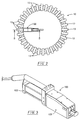
- the boiler tube flared-end shear tool 100 of the present invention pertains generally to the removal of the tube flared- end segments that are initially retained in the steam and mud drum peripheral walls and, as illustrated in Figure 2, such tool is basically utilized from a position within the applicable boiler drum.
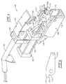
- Figures 3 and 4 best illustrate the basic construction details of tool assembly 100 .
- the conventional system for supplying the flow of pressurized fluid which may be either pressurized hydraulic fluid or compressed air, to the conventional bi-directional pressure actuator subassembly 102 included with tool 100 ).
- Tool assembly 100 includes, in addition to cylinder 104 and piston rod 106 of actuator subassembly 102 , a tool head subassembly 108 that is basically comprised of rigid frame element 110 , anvil block element 112 having shear cavity 114 , rotatable shear blade element 116 carried in anvil block element 112 by pivot shaft 118 , wear plate element 120 supported by frame 110 and extending from anvil block 112 to actuator subassembly 102 , and cam body 122 supported by wear plate 120 and connected to the piston rod element 106 for reciprocation.
- an undercut relief 115 is formed in shear blade element 116 just behind a shear edge 117 formed thereof.
- a bending edge 119 is located adjacent and in front of shear edge 117 .
- Guide elements 124 and 126 are fixedly secured to opposite faces of cam body member 122 .
- a lug pin 128 mounted in and projecting from opposite sides of the rear portion of shear blade element 116 , co-operates with the ways provided in guide elements 124 and 126 and causes rotation of shear blade element 116 about pivot pin 118 as cam body 122 and its included guide member 124 and 126 are reciprocated by actuator subassembly 102 .
- the upper surface 113a of the nose portion 113 of anvil block element 112 is advantageously provided with upwardly projecting locating lugs 130 (see Figures 4 and 7). Lugs 130 engage longitudinal gap edges previously cut in boiler tube segment 12 when nose 113 of shear block element 112 is property inserted in that tube segment for the subsequent shearing and bending steps resulting from operation of actuator subassembly 102 . It may be observed that upper surface 113a of nose portion 113 projects forward of the shear edge 117 formed on shear blade element 116 .
- actuator subassembly 102 advances cam body 122 to rotate shear blade element 116 about shaft 118 , shear edge 117 engages gap metal 121 at 121a inwardly of gap metal edge 121b to cause such gap metal to be sheared and bent downwardly about anvil edge 113a .
- shear blade element 116 By causing shear blade element 116 to engage gap metal 121 inwardly of its outer edge 121b , blade element is drawn into tube segment 12 thereby preventing blade element 116 from moving away from or backing out of engagement with tub segment 12 .
- Undercut relief 115 acts to receive the flared edge or end 121b of a tube segment 12 to prevent shear blade element 116 from engaging said flared edge prior to engagement with tube segment 12 at location 121a ,
- tool assembly 100 also includes tool head cover 132, which is removably attached to frame member 110 , housing 134 for the power system direction control valve, and tool handle 136.
- Components 134 and 136 are preferably removably attached to and carried by actuator subassembly 102.
- Subassembly 102 is removably mounted on tool frame 110 by the conventional threaded fasteners designated 103 .
Landscapes
- Engineering & Computer Science (AREA)
- Mechanical Engineering (AREA)
- Physics & Mathematics (AREA)
- Thermal Sciences (AREA)
- General Engineering & Computer Science (AREA)
- Perforating, Stamping-Out Or Severing By Means Other Than Cutting (AREA)
- Shearing Machines (AREA)
Applications Claiming Priority (2)
| Application Number | Priority Date | Filing Date | Title |
|---|---|---|---|
| US416693 | 1999-10-12 | ||
| US09/416,693 US6182354B1 (en) | 1999-10-12 | 1999-10-12 | Boiler tube segment and bend tool |
Publications (2)
| Publication Number | Publication Date |
|---|---|
| EP1092923A2 true EP1092923A2 (fr) | 2001-04-18 |
| EP1092923A3 EP1092923A3 (fr) | 2001-09-12 |
Family
ID=23650931
Family Applications (1)
| Application Number | Title | Priority Date | Filing Date |
|---|---|---|---|
| EP00203280A Withdrawn EP1092923A3 (fr) | 1999-10-12 | 2000-09-21 | Dispositif pour cisailler et plier un segment d'un tube de chaudière |
Country Status (3)
| Country | Link |
|---|---|
| US (1) | US6182354B1 (fr) |
| EP (1) | EP1092923A3 (fr) |
| CA (1) | CA2322724C (fr) |
Families Citing this family (12)
| Publication number | Priority date | Publication date | Assignee | Title |
|---|---|---|---|---|
| US6430790B1 (en) * | 2000-04-26 | 2002-08-13 | Advanced Cutting Technologies, Ltd. | Boiler tube flared-end segment peeler tool |
| US7305756B2 (en) * | 2004-04-22 | 2007-12-11 | Barcock & Wilcox Canada Ltd. | Tube extracting device |
| US7194800B2 (en) * | 2004-06-07 | 2007-03-27 | Babcick & Wilcox Canada, Ltd. | Internal tube extracting device with a cylindrical collapsing wedge |
| US7146716B2 (en) * | 2004-06-08 | 2006-12-12 | Babcock & Wilcox Canada Ltd. | External tube extraction device with a cylindrical collapsing wedge |
| US7168143B2 (en) * | 2004-06-30 | 2007-01-30 | Babcock & Wilcox Canada Ltd. | External tube deforming extraction device |
| US8348253B2 (en) * | 2006-03-08 | 2013-01-08 | Mcclure Mark W | Modified boiler wall tube tool |
| US7657985B2 (en) * | 2006-03-08 | 2010-02-09 | Mcclure Mark W | Modified boiler wall tube tool |
| US20070296133A1 (en) * | 2006-06-21 | 2007-12-27 | Mcclure Mark W | Modified Boiler Wall Tube Tool Having Inhibiting Means |
| CN102225501A (zh) * | 2011-03-24 | 2011-10-26 | 中色奥博特铜铝业有限公司 | 返修空调换热器铜管组件的方法及装置 |
| CN103600216A (zh) * | 2013-11-25 | 2014-02-26 | 河北亚大汽车塑料制品有限公司 | 一种塑料管总成伺服装配机 |
| US9766605B1 (en) | 2014-08-07 | 2017-09-19 | Waymo Llc | Methods and systems for synthesis of a waveguide array antenna |
| US9876282B1 (en) | 2015-04-02 | 2018-01-23 | Waymo Llc | Integrated lens for power and phase setting of DOEWG antenna arrays |
Citations (1)
| Publication number | Priority date | Publication date | Assignee | Title |
|---|---|---|---|---|
| US5893209A (en) | 1997-09-22 | 1999-04-13 | Weeks; Bruce V. | Apparatus for effecting boiler tube removal |
Family Cites Families (9)
| Publication number | Priority date | Publication date | Assignee | Title |
|---|---|---|---|---|
| US2507201A (en) * | 1946-09-17 | 1950-05-09 | Evans Clair Otto | Tool for removing tubes from tube sheets |
| US3628246A (en) * | 1968-09-06 | 1971-12-21 | Carrier Corp | Apparatus for tube removal |
| US3857158A (en) * | 1972-12-19 | 1974-12-31 | D Costello | Method and apparatus for removing condenser tubes from surface condensers |
| US3835520A (en) * | 1973-09-10 | 1974-09-17 | Harris R | Tube pulling apparatus |
| US4967468A (en) * | 1986-10-27 | 1990-11-06 | Torque And Tension Equipment Inc. | Apparatus for fixing boiler tubes during replacement of same |
| FR2666879B1 (fr) * | 1990-09-19 | 1993-03-19 | Framatome Sa | Procede de remplacement d'un tube d'un echangeur de chaleur a tubes droits et utilisation de ce procede. |
| DE19609958C2 (de) * | 1996-03-14 | 2000-06-15 | Dillinger Stahlbau | Verfahren zur Reparatur von Wärmetauscherrohren im Inneren von geschlossenen Röhrenapparaten |
| US5826334A (en) * | 1997-03-10 | 1998-10-27 | Advanced Cutting Technologies, Inc. | Boiler tube removal method |
| EP1096199A2 (fr) * | 1999-10-27 | 2001-05-02 | Advanced Cutting Technologies, Ltd. | Méthode d'enlèvement d'un tube de chaudière |
-
1999
- 1999-10-12 US US09/416,693 patent/US6182354B1/en not_active Expired - Fee Related
-
2000
- 2000-09-21 EP EP00203280A patent/EP1092923A3/fr not_active Withdrawn
- 2000-10-10 CA CA002322724A patent/CA2322724C/fr not_active Expired - Fee Related
Patent Citations (1)
| Publication number | Priority date | Publication date | Assignee | Title |
|---|---|---|---|---|
| US5893209A (en) | 1997-09-22 | 1999-04-13 | Weeks; Bruce V. | Apparatus for effecting boiler tube removal |
Also Published As
| Publication number | Publication date |
|---|---|
| US6182354B1 (en) | 2001-02-06 |
| EP1092923A3 (fr) | 2001-09-12 |
| CA2322724A1 (fr) | 2001-04-12 |
| CA2322724C (fr) | 2006-11-07 |
Similar Documents
| Publication | Publication Date | Title |
|---|---|---|
| US6182354B1 (en) | Boiler tube segment and bend tool | |
| US5974642A (en) | Boiler tube removal apparatus | |
| US7625518B2 (en) | Smelt spout opening cleaner, cleaning head and apparatus | |
| CA2322722C (fr) | Outil de compression pour tube de chaudiere a bout evase | |
| US6308390B1 (en) | Door hinge pin removal tool | |
| NO179403B (no) | Muttersplitter | |
| CA2322725C (fr) | Outil de deroulage de tubes de chaudiere a bout evase | |
| US6925911B1 (en) | Fluid-operated power tool | |
| CN109209297A (zh) | 一种通刮一体化工具 | |
| US6430790B1 (en) | Boiler tube flared-end segment peeler tool | |
| US4246699A (en) | Nut cutting or nut breaking tool | |
| JP3843511B2 (ja) | リベッター装置およびこれの給油方法 | |
| JP4009395B2 (ja) | 高信頼性プレ−ト切断特性を有する大型解体剪断機 | |
| CA2018610C (fr) | Rupteur de canalisation | |
| JP2004082273A (ja) | 天井枠分離工具 | |
| US20060000074A1 (en) | External tube deforming extraction device | |
| CN212512687U (zh) | 火药残渣清洁工具 | |
| CN121066503B (zh) | 一种大直径复合片扩孔钻头 | |
| CN219881436U (zh) | 一种多功能手动拆解工具 | |
| US3215008A (en) | Powered edge-shaping tools | |
| JPS60118333A (ja) | 油圧式穴明け機のラムの調整機構 | |
| CN221415262U (zh) | 一种电火花紧固件拆卸系统 | |
| CA3095421A1 (fr) | Procede et appareil d'application de couple | |
| Tang et al. | Formation mechanism of external finned tubes by extrusion-plough method. | |
| CN215034196U (zh) | 去刺刮刀 |
Legal Events
| Date | Code | Title | Description |
|---|---|---|---|
| PUAI | Public reference made under article 153(3) epc to a published international application that has entered the european phase |
Free format text: ORIGINAL CODE: 0009012 |
|
| AK | Designated contracting states |
Kind code of ref document: A2 Designated state(s): DE ES FR GB IT SE Kind code of ref document: A2 Designated state(s): AT BE CH CY DE DK ES FI FR GB GR IE IT LI LU MC NL PT SE |
|
| AX | Request for extension of the european patent |
Free format text: AL;LT;LV;MK;RO;SI |
|
| PUAL | Search report despatched |
Free format text: ORIGINAL CODE: 0009013 |
|
| AK | Designated contracting states |
Kind code of ref document: A3 Designated state(s): AT BE CH CY DE DK ES FI FR GB GR IE IT LI LU MC NL PT SE |
|
| AX | Request for extension of the european patent |
Free format text: AL;LT;LV;MK;RO;SI |
|
| RIC1 | Information provided on ipc code assigned before grant |
Free format text: 7F 22B 37/58 A, 7B 23D 21/00 B, 7B 23P 19/02 B |
|
| 17P | Request for examination filed |
Effective date: 20020104 |
|
| AKX | Designation fees paid |
Free format text: DE ES FR GB IT SE |
|
| 17Q | First examination report despatched |
Effective date: 20080411 |
|
| STAA | Information on the status of an ep patent application or granted ep patent |
Free format text: STATUS: THE APPLICATION IS DEEMED TO BE WITHDRAWN |
|
| 18D | Application deemed to be withdrawn |
Effective date: 20080822 |