EP1092937A2 - Behälter zur Installation im Meeresboden - Google Patents
Behälter zur Installation im Meeresboden Download PDFInfo
- Publication number
- EP1092937A2 EP1092937A2 EP00309046A EP00309046A EP1092937A2 EP 1092937 A2 EP1092937 A2 EP 1092937A2 EP 00309046 A EP00309046 A EP 00309046A EP 00309046 A EP00309046 A EP 00309046A EP 1092937 A2 EP1092937 A2 EP 1092937A2
- Authority
- EP
- European Patent Office
- Prior art keywords
- enclosure
- container
- impeller
- vessel
- signal
- Prior art date
- Legal status (The legal status is an assumption and is not a legal conclusion. Google has not performed a legal analysis and makes no representation as to the accuracy of the status listed.)
- Granted
Links
Images



Classifications
-
- E—FIXED CONSTRUCTIONS
- E02—HYDRAULIC ENGINEERING; FOUNDATIONS; SOIL SHIFTING
- E02F—DREDGING; SOIL-SHIFTING
- E02F3/00—Dredgers; Soil-shifting machines
- E02F3/04—Dredgers; Soil-shifting machines mechanically-driven
- E02F3/88—Dredgers; Soil-shifting machines mechanically-driven with arrangements acting by a sucking or forcing effect, e.g. suction dredgers
- E02F3/90—Component parts, e.g. arrangement or adaptation of pumps
- E02F3/92—Digging elements, e.g. suction heads
- E02F3/9206—Digging devices using blowing effect only, like jets or propellers
-
- B—PERFORMING OPERATIONS; TRANSPORTING
- B63—SHIPS OR OTHER WATERBORNE VESSELS; RELATED EQUIPMENT
- B63B—SHIPS OR OTHER WATERBORNE VESSELS; EQUIPMENT FOR SHIPPING
- B63B21/00—Tying-up; Shifting, towing, or pushing equipment; Anchoring
- B63B21/24—Anchors
- B63B21/26—Anchors securing to bed
- B63B21/27—Anchors securing to bed by suction
-
- E—FIXED CONSTRUCTIONS
- E02—HYDRAULIC ENGINEERING; FOUNDATIONS; SOIL SHIFTING
- E02F—DREDGING; SOIL-SHIFTING
- E02F5/00—Dredgers or soil-shifting machines for special purposes
- E02F5/28—Dredgers or soil-shifting machines for special purposes for cleaning watercourses or other ways
-
- E—FIXED CONSTRUCTIONS
- E02—HYDRAULIC ENGINEERING; FOUNDATIONS; SOIL SHIFTING
- E02F—DREDGING; SOIL-SHIFTING
- E02F7/00—Equipment for conveying or separating excavated material
-
- E—FIXED CONSTRUCTIONS
- E21—EARTH OR ROCK DRILLING; MINING
- E21B—EARTH OR ROCK DRILLING; OBTAINING OIL, GAS, WATER, SOLUBLE OR MELTABLE MATERIALS OR A SLURRY OF MINERALS FROM WELLS
- E21B7/00—Special methods or apparatus for drilling
- E21B7/18—Drilling by liquid or gas jets, with or without entrained pellets
- E21B7/185—Drilling by liquid or gas jets, with or without entrained pellets underwater
-
- F—MECHANICAL ENGINEERING; LIGHTING; HEATING; WEAPONS; BLASTING
- F41—WEAPONS
- F41F—APPARATUS FOR LAUNCHING PROJECTILES OR MISSILES FROM BARRELS, e.g. CANNONS; LAUNCHERS FOR ROCKETS OR TORPEDOES; HARPOON GUNS
- F41F3/00—Rocket or torpedo launchers
- F41F3/04—Rocket or torpedo launchers for rockets
- F41F3/07—Underwater launching-apparatus
-
- F—MECHANICAL ENGINEERING; LIGHTING; HEATING; WEAPONS; BLASTING
- F41—WEAPONS
- F41F—APPARATUS FOR LAUNCHING PROJECTILES OR MISSILES FROM BARRELS, e.g. CANNONS; LAUNCHERS FOR ROCKETS OR TORPEDOES; HARPOON GUNS
- F41F3/00—Rocket or torpedo launchers
- F41F3/08—Rocket or torpedo launchers for marine torpedoes
- F41F3/10—Rocket or torpedo launchers for marine torpedoes from below the surface of the water
Definitions
- This invention relates to enclosures for installation on the seabed to carry communications and/or weapon systems to be deployed from the seabed.
- European Patent Specification No. 0110554 discloses an underwater weapon system comprising an elongate outer container which is buried or partially buried in the seabed in an upright position using self-burying means which are at the bottom end of the container and which preferably comprise both pump means for removing sand or silt and rotary material displacing means, e.g. an auger for boring a hole in the seabed or rotary stirring means.
- the weapon is a self-propelled device with guidance means and is housed within an inner container which is telescopically arranged within the outer container.
- US Patent Specification No. 6044745 discloses an enclosure for instalation on the seabed comprising an outer cylindrical container one of the which is more buoyant than the other so that the container lies in a vertical orientation when disposed in the sea and auger devices at the other end of the container for activating sand/silt/shingle on the seabed to create a cavity below the container into which the container can self-bury.
- the container has a payload compartment within the container for holding weaponry, listening, identification recording and/or communications equipment.
- the container wall is formed with a plurality of separate passages extending spirally from inlets at the lower end of the container upwardly to outlets at the top of the container through which activated sand/silt/shingle and water generated at the lower end of the container can flow upwardly and freely as the container self-buries in the seabed.
- the invention provides an enclosure for installation in the seabed comprising an elongate container for holding a payload, the container having a plurality of passages extending lengthwise of the container and impeller means at one end of the container to be the lower end of the container on installation for drawing water through at least one of said passages from the other end of the container to form a slurry with the material of the seabed and for discharging slurry formed at said one end of the container through at least one other of said passages to said other end of the container for discharge into the surrounding water.
- the enclosure has inner and outer concentric passageways extending lengthwise thereof and said impeller has a blade or blades extending across the inner and outer passageways, the blade or blades having a first section pitched to draw water down one of the passageways and a second portion pitched to discharge slurry up the other of the passageways.
- the impeller may be rotatable about an axis which is co-axial with the axes of the inner and outer concentric passageways, inner portions of the blade or blades of the impeller being pitched to draw water down the inner passageway and the outer portion of the blade or blades of the impeller being pitched to propel slurry up the outer passageway.
- the outer passageway may have an annular outlet port partway up the container for the discharge of slurry outwardly of the container.
- the payload may include a motor for driving the impeller and a power supply for the motor.
- the payload may include communication means for receiving/ transmitting signals which may be sonar, acoustic or seismic.
- the payload may also include a weapon system or systems.
- MHVs Mine Hunting Vessels
- All are designed to a very high standard, costly to build and loaded with even more expensive equipment. They relay on complex and heavy sweep gear, hull mounted sonars, variable depth sonars (Vds), remotely operated vehicles (ROVs) and unmanned underwater vehicles (UUVs) to act as "eyes" when trying to find, identify, and neutralise targets.
- Vds variable depth sonars
- ROVs remotely operated vehicles
- UUVs unmanned underwater vehicles
- sonars are mounted on ROVs or UUVs and which for each of designation, which for each of designation, which are hereinafter referred to as "scouts".
- the invention provides an underwater communication device comprising means to detect a signal generated by a vessel in the vicinity of the device and means responsive to receipt of such signal to transmit a decoy sonar signal to the vessel.
- Each unit which could be constructed of or coated with non reflective materials, will contain the necessary electronic equipment e.g. receivers, sensors, hydrophones, magnetometers, transducers, transponders, signal generators, aerials, transmitters etc. to enable it not only to accept coded instructions, which might be either seismic or acoustic in origin, but also to ensure that when alerted/activated by the presence of an intruding vessel or decoy, either surface or subsurface, that the signals, particularly such sonar signals emanating from the intruder may:
- buoyant radio beacon which would:
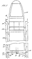
- the drawing shows an enclosure indicated generally at 10 for installation at a strategic location on the seabed which is indicated at 11.
- the enclosure comprises outer and inner concentric containers 12, 13 and an inner payload assembly indicated generally at 14 which will be described in greater detail below.
- the inner and outer containers define between them an outer annular passageway 12a extending between the containers from the top to the lower end of the enclosure.
- the outer container has a nozzle plate 15 mounted within the end of the container to direct spoil from the surface of the seabed into the outer passageway 12a as indicated by the arrows.
- An inner annular passageway 13a is formed between the inner container 13 and the payload assembly extending through the enclosure.
- the inner container 13 Towards the upper end of the enclosure, the inner container 13 is stepped outwardly at 16 to form an enlarged upper end 17 having an open entry indicated at 18 at the top of the enclosure to receive water to flow downwardly through the passageway 13a in the direction of the arrows.
- the outer container 12 terminates at its upper end below the step 16 to provide an annular outlet port 19 for release of slurry passing up the outer passageway 12a to the surrounding sea.
- the payload assembly 14 includes an impeller assembly indicated generally at 20 having a drive shaft 21 mounted co axially with the axis of the inner and outer containers in the lower part 22 of the payload assembly which also contains a battery powered electric motor for rotating the shaft.
- the impeller has laterally extending blades 23, each of which has an inner section 24 extending across the lower end of the inner passage 13a immediately below the inner container 13 and pitched to draw water down the passage 25 from the inlet end 18 at the top of the enclosure. The water is directed by the blade portions 24 in the direction of the arrows 26 inwardly and downwardly onto the seabed 11 below the payload assembly to fluidise the material of the seabed with water.
- the outer portions 27 of the blades are pitched to draw the fluidised seabed material upwardly from the central region below the payload assembly in the direction of the arrows 28 into the outer passage 12a between the inner and outer containers and upwardly to the outlet 19.
- the single impeller generates a downward flow of water in the inner passage 25 and an upward flow of a slurry of material from the seabed and water in the outer passage 12a to excavate the seabed immediately below enclosure 10.
- the enclosure is allowed to drop progressively into the seabed thereby bearing itself to avoid both detection and damage from equipment or implements being drawn over the seabed.
- the payload assembly 14 of the enclosure may contain a variety of different communications/weapon systems.
- the assembly may include a signal generator unit 35, a process unit 36, an analyser unit 37, a control unit 38, vessel generated acoustic signal receivers 39, sonar generated acoustic signal receivers 40, transmitter units (sonar, acoustic, seismic) 41, a buoyancy hydrophone chamber 42, directional transducer 43, an acoustic imaging transducer 44 and a pressure detection unit 45.
- a signal generator unit 35 may include a signal generator unit 35, a process unit 36, an analyser unit 37, a control unit 38, vessel generated acoustic signal receivers 39, sonar generated acoustic signal receivers 40, transmitter units (sonar, acoustic, seismic) 41, a buoyancy hydrophone chamber 42, directional transducer 43, an acoustic imaging transducer 44 and a pressure detection unit 45.
- a signal generator unit 35 may include a signal generator
- Figures 2 to 4 show a modified form of the enclosure in which the lower part of the container wall 13 below the payload 14 has an annular slit 50 through which the impeller extends to operate the outer passageway 12a. Also the lower end of the container 13 has an inwardly curved exit 51 to direct water inwardly as indicated by the arrows. In Figure 5 the lower end of the container is angled inwardly as indicated at 52 for the same purpose.
- Each unit which could be constructed of or coated with non reflective materials, will contain the necessary electronic equipment e.g. receivers, sensors, hydrophones, magnetometers, transducers, transponders, signal generators, aerials, transmitters etc. to enable it not only to accept coded instructions, which might be either seismic or acoustic in origin, but also to ensure that when alerted/activated by the presence of an intruding vessel or decoy, either surface or subsurface, that the signals, particularly such sonar signals emanating from the intruder may:
- buoyant radio beacon which would:
- a searching MHV will receive a multiplicity of signals in response to each signal which it has generated and transmitted.
- each Lorelei could be programmed on/to a specific range of frequencies, and a quantity of them could thereby cover the whole of the likely spectrum.
Landscapes
- Engineering & Computer Science (AREA)
- Mining & Mineral Resources (AREA)
- General Engineering & Computer Science (AREA)
- Mechanical Engineering (AREA)
- Structural Engineering (AREA)
- Civil Engineering (AREA)
- Ocean & Marine Engineering (AREA)
- Geology (AREA)
- Life Sciences & Earth Sciences (AREA)
- Chemical & Material Sciences (AREA)
- Environmental & Geological Engineering (AREA)
- Geochemistry & Mineralogy (AREA)
- Physics & Mathematics (AREA)
- General Life Sciences & Earth Sciences (AREA)
- Combustion & Propulsion (AREA)
- Fluid Mechanics (AREA)
- Measurement Of Velocity Or Position Using Acoustic Or Ultrasonic Waves (AREA)
- Artificial Fish Reefs (AREA)
- Underground Or Underwater Handling Of Building Materials (AREA)
- Geophysics And Detection Of Objects (AREA)
- Catching Or Destruction (AREA)
- Cultivation Of Seaweed (AREA)
- Placing Or Removing Of Piles Or Sheet Piles, Or Accessories Thereof (AREA)
- Telescopes (AREA)
Applications Claiming Priority (2)
| Application Number | Priority Date | Filing Date | Title |
|---|---|---|---|
| GBGB9924246.3A GB9924246D0 (en) | 1999-10-13 | 1999-10-13 | Improvements in or relating to enclosures for installations on the seabed |
| GB9924246 | 1999-10-13 |
Publications (3)
| Publication Number | Publication Date |
|---|---|
| EP1092937A2 true EP1092937A2 (de) | 2001-04-18 |
| EP1092937A3 EP1092937A3 (de) | 2002-04-03 |
| EP1092937B1 EP1092937B1 (de) | 2006-12-13 |
Family
ID=10862689
Family Applications (1)
| Application Number | Title | Priority Date | Filing Date |
|---|---|---|---|
| EP00309046A Expired - Lifetime EP1092937B1 (de) | 1999-10-13 | 2000-10-13 | Behälter zur Installation im Meeresboden |
Country Status (6)
| Country | Link |
|---|---|
| US (1) | US6371003B1 (de) |
| EP (1) | EP1092937B1 (de) |
| AT (1) | ATE348310T1 (de) |
| AU (1) | AU6652500A (de) |
| DE (1) | DE60032306T2 (de) |
| GB (1) | GB9924246D0 (de) |
Cited By (2)
| Publication number | Priority date | Publication date | Assignee | Title |
|---|---|---|---|---|
| CN103890613A (zh) * | 2011-09-21 | 2014-06-25 | 移动科学有限公司 | 海床装置的布置 |
| WO2019202298A1 (en) * | 2018-04-20 | 2019-10-24 | Rotech Group Limited | Improvements in and relating to underwater excavation apparatus |
Families Citing this family (9)
| Publication number | Priority date | Publication date | Assignee | Title |
|---|---|---|---|---|
| US20110253026A1 (en) * | 2010-04-19 | 2011-10-20 | Raytheon Company | Remotely-triggered submerged launch canisters |
| US9381986B2 (en) | 2012-11-21 | 2016-07-05 | Seabed Geosolutions B.V. | Jet-pump-based autonomous underwater vehicle and method for coupling to ocean bottom during marine seismic survey |
| US9457879B2 (en) * | 2012-12-17 | 2016-10-04 | Seabed Geosolutions B.V. | Self-burying autonomous underwater vehicle and method for marine seismic surveys |
| JP5827214B2 (ja) * | 2012-12-27 | 2015-12-02 | 日本システム企画株式会社 | 海底設置型の浮力式魚雷収納発射システム及び浮力上昇式の魚雷 |
| NO20131318A1 (no) * | 2013-09-30 | 2015-03-31 | Vetco Gray Scandinavia As | Selvnedgravende fundamentinnretning |
| US10571222B2 (en) * | 2017-09-07 | 2020-02-25 | Stephen Tomás Strocchia-Rivera | Payload launching apparatus and method |
| US20200256309A1 (en) * | 2019-02-10 | 2020-08-13 | Stephen Tomás Strocchia-Rivera | Deep Water Pressure Electricity Generating Method, Apparatus and System |
| CN115352575B (zh) * | 2022-07-12 | 2024-10-11 | 上海交通大学 | 带叶轮和飞轮的动力贯入锚 |
| US20240326966A1 (en) * | 2023-03-28 | 2024-10-03 | The United States Of America As Represented By The Secretary Of The Navy | Data Pod Release System |
Citations (2)
| Publication number | Priority date | Publication date | Assignee | Title |
|---|---|---|---|---|
| EP0110554A2 (de) | 1982-10-28 | 1984-06-13 | Underwater Storage Limited | Unterwasser-Waffensysteme |
| US6044745A (en) | 1995-08-16 | 2000-04-04 | Lawborough Consultants Limited | Seabed enclosures |
Family Cites Families (16)
| Publication number | Priority date | Publication date | Assignee | Title |
|---|---|---|---|---|
| US1853379A (en) * | 1926-12-29 | 1932-04-12 | Alexander G Rotinoff | Caisson and method of and means for sinking the same |
| US2931187A (en) | 1957-07-08 | 1960-04-05 | Perkins Starling | Coffer-dam |
| US3158062A (en) | 1959-10-12 | 1964-11-24 | Pneumo Dynamics Corp | Missile container and launcher |
| US3499364A (en) | 1959-11-19 | 1970-03-10 | Us Navy | Apparatus for submerged launching of missiles |
| US4274333A (en) | 1959-12-28 | 1981-06-23 | The United States Of America As Represented By The Secretary Of The Navy | Deepwater target-seeking mines |
| US3035285A (en) | 1961-09-18 | 1962-05-22 | Jr Walter G Squires | Explosively anchored buoy |
| US3072022A (en) | 1961-10-30 | 1963-01-08 | Davis M Wood | Missile container suspension system |
| US3137203A (en) | 1962-01-31 | 1964-06-16 | Brown Joseph | Underwater missile launching system |
| US3279319A (en) | 1964-06-19 | 1966-10-18 | Joseph W Semonian | Floatable rocket launcher |
| US3301132A (en) | 1965-07-29 | 1967-01-31 | Guenther W Lehmann | Submersible missile launching vehicle |
| US3916634A (en) | 1973-03-12 | 1975-11-04 | Roy J Woodruff | Method for forming holes in earth and setting subterranean structures therein |
| GB1547695A (en) * | 1977-03-10 | 1979-06-27 | Secretary Industry Brit | Anchoring devices |
| US4395952A (en) | 1980-12-04 | 1983-08-02 | Hickey Christopher D D | Underwater weapon systems |
| GB2134232B (en) | 1982-12-10 | 1986-07-02 | Underwater Storage Ltd | Underwater weapon system |
| GB2222805B (en) * | 1988-09-02 | 1992-04-29 | Lawborough Consultants | Improvements in or relating to underwater communication devices |
| US5837919A (en) | 1996-12-05 | 1998-11-17 | The United States Of America As Represented By The Secretary Of The Navy | Portable launcher |
-
1999
- 1999-10-13 GB GBGB9924246.3A patent/GB9924246D0/en not_active Ceased
-
2000
- 2000-10-13 AU AU66525/00A patent/AU6652500A/en not_active Abandoned
- 2000-10-13 AT AT00309046T patent/ATE348310T1/de not_active IP Right Cessation
- 2000-10-13 US US09/689,765 patent/US6371003B1/en not_active Expired - Fee Related
- 2000-10-13 EP EP00309046A patent/EP1092937B1/de not_active Expired - Lifetime
- 2000-10-13 DE DE60032306T patent/DE60032306T2/de not_active Expired - Lifetime
Patent Citations (3)
| Publication number | Priority date | Publication date | Assignee | Title |
|---|---|---|---|---|
| EP0110554A2 (de) | 1982-10-28 | 1984-06-13 | Underwater Storage Limited | Unterwasser-Waffensysteme |
| US6044745A (en) | 1995-08-16 | 2000-04-04 | Lawborough Consultants Limited | Seabed enclosures |
| EP0844963B1 (de) | 1995-08-16 | 2000-06-28 | Lawborough Consultants Limited | Verbesserungen an unterwasser-kommunikationsgeräten |
Cited By (3)
| Publication number | Priority date | Publication date | Assignee | Title |
|---|---|---|---|---|
| CN103890613A (zh) * | 2011-09-21 | 2014-06-25 | 移动科学有限公司 | 海床装置的布置 |
| WO2019202298A1 (en) * | 2018-04-20 | 2019-10-24 | Rotech Group Limited | Improvements in and relating to underwater excavation apparatus |
| US12163309B2 (en) | 2018-04-20 | 2024-12-10 | Rotech Group Limited | Underwater excavation apparatus |
Also Published As
| Publication number | Publication date |
|---|---|
| EP1092937A3 (de) | 2002-04-03 |
| DE60032306D1 (de) | 2007-01-25 |
| AU6652500A (en) | 2001-04-26 |
| DE60032306T2 (de) | 2007-07-12 |
| GB9924246D0 (en) | 2000-09-06 |
| EP1092937B1 (de) | 2006-12-13 |
| US6371003B1 (en) | 2002-04-16 |
| ATE348310T1 (de) | 2007-01-15 |
Similar Documents
| Publication | Publication Date | Title |
|---|---|---|
| AU2018206756B2 (en) | Underwater system and method | |
| US6371003B1 (en) | Enclosures for installation on the seabed | |
| US6802237B1 (en) | System and method for neutralization of mines using robotics and penetrating rods | |
| EP1588186B1 (de) | Sonargruppensystem | |
| EP0844963B1 (de) | Verbesserungen an unterwasser-kommunikationsgeräten | |
| US9242708B2 (en) | Neutralization of a target with an acoustic wave | |
| US20250374898A1 (en) | Ropeless fishing system and method | |
| US5277117A (en) | Underwater mine countermeasure warfare system | |
| US5144587A (en) | Expendable moving echo radiator | |
| US4395952A (en) | Underwater weapon systems | |
| Garwin | Will Strategic Submarines Be Vulnerable? | |
| EP0357441B1 (de) | Unterwasser-Kommunikationsvorrichtungen | |
| GB2048439A (en) | Improvements in or relating to underwater weapons | |
| US5245588A (en) | Regenerative radio-frequency wire detector | |
| US4972388A (en) | Electrical cable marker | |
| NO320214B1 (no) | Forbedret anordning for innkapslinger for installasjon pa havbunnen | |
| US4975912A (en) | Brackish-water wire detector | |
| WO2010025951A2 (en) | Marine defence system | |
| KR20170135203A (ko) | 자율 기동 전개 방식의 음파탐지 네트워크 시스템 및 대잠/대함 공격 시스템과 그 구성 방법 | |
| Fritz | Computer-aided detection of rapid, overt, airborne, reconnaissance data with the capability of removing oceanic noises | |
| GB2468042A (en) | Detection and identification of submerged vessels | |
| KR20150057391A (ko) | 영해 보호를 위한 감시시스템 | |
| SE2330230A1 (en) | An underwater unmanned vehicle docking arrangement | |
| EP0053210B1 (de) | Unterwasserwaffe | |
| Elminowicz et al. | Application of DDS and magnetic barrier cooperating with acoustic barriers and tethered sonobuoys for harbour and anchorage underwater protection |
Legal Events
| Date | Code | Title | Description |
|---|---|---|---|
| PUAI | Public reference made under article 153(3) epc to a published international application that has entered the european phase |
Free format text: ORIGINAL CODE: 0009012 |
|
| AK | Designated contracting states |
Kind code of ref document: A2 Designated state(s): AT BE CH CY DE DK ES FI FR GB GR IE IT LI LU MC NL PT SE |
|
| AX | Request for extension of the european patent |
Free format text: AL;LT;LV;MK;RO;SI |
|
| PUAL | Search report despatched |
Free format text: ORIGINAL CODE: 0009013 |
|
| AK | Designated contracting states |
Kind code of ref document: A3 Designated state(s): AT BE CH CY DE DK ES FI FR GB GR IE IT LI LU MC NL PT SE |
|
| AX | Request for extension of the european patent |
Free format text: AL;LT;LV;MK;RO;SI |
|
| RIC1 | Information provided on ipc code assigned before grant |
Free format text: 7F 41F 3/07 A, 7F 41F 3/10 B, 7F 42B 22/06 B, 7B 63B 21/26 B, 7E 02F 7/00 B, 7E 21B 7/12 B, 7E 21B 7/18 B |
|
| 17P | Request for examination filed |
Effective date: 20020422 |
|
| AKX | Designation fees paid |
Free format text: AT BE CH CY DE DK ES FI FR GB GR IE IT LI LU MC NL PT SE |
|
| 17Q | First examination report despatched |
Effective date: 20041203 |
|
| GRAP | Despatch of communication of intention to grant a patent |
Free format text: ORIGINAL CODE: EPIDOSNIGR1 |
|
| GRAS | Grant fee paid |
Free format text: ORIGINAL CODE: EPIDOSNIGR3 |
|
| GRAA | (expected) grant |
Free format text: ORIGINAL CODE: 0009210 |
|
| AK | Designated contracting states |
Kind code of ref document: B1 Designated state(s): AT BE CH CY DE DK ES FI FR GB GR IE IT LI LU MC NL PT SE |
|
| PG25 | Lapsed in a contracting state [announced via postgrant information from national office to epo] |
Ref country code: IT Free format text: LAPSE BECAUSE OF FAILURE TO SUBMIT A TRANSLATION OF THE DESCRIPTION OR TO PAY THE FEE WITHIN THE PRESCRIBED TIME-LIMIT;WARNING: LAPSES OF ITALIAN PATENTS WITH EFFECTIVE DATE BEFORE 2007 MAY HAVE OCCURRED AT ANY TIME BEFORE 2007. THE CORRECT EFFECTIVE DATE MAY BE DIFFERENT FROM THE ONE RECORDED. Effective date: 20061213 Ref country code: CH Free format text: LAPSE BECAUSE OF FAILURE TO SUBMIT A TRANSLATION OF THE DESCRIPTION OR TO PAY THE FEE WITHIN THE PRESCRIBED TIME-LIMIT Effective date: 20061213 Ref country code: FI Free format text: LAPSE BECAUSE OF FAILURE TO SUBMIT A TRANSLATION OF THE DESCRIPTION OR TO PAY THE FEE WITHIN THE PRESCRIBED TIME-LIMIT Effective date: 20061213 Ref country code: AT Free format text: LAPSE BECAUSE OF FAILURE TO SUBMIT A TRANSLATION OF THE DESCRIPTION OR TO PAY THE FEE WITHIN THE PRESCRIBED TIME-LIMIT Effective date: 20061213 Ref country code: DK Free format text: LAPSE BECAUSE OF FAILURE TO SUBMIT A TRANSLATION OF THE DESCRIPTION OR TO PAY THE FEE WITHIN THE PRESCRIBED TIME-LIMIT Effective date: 20061213 Ref country code: NL Free format text: LAPSE BECAUSE OF FAILURE TO SUBMIT A TRANSLATION OF THE DESCRIPTION OR TO PAY THE FEE WITHIN THE PRESCRIBED TIME-LIMIT Effective date: 20061213 Ref country code: BE Free format text: LAPSE BECAUSE OF FAILURE TO SUBMIT A TRANSLATION OF THE DESCRIPTION OR TO PAY THE FEE WITHIN THE PRESCRIBED TIME-LIMIT Effective date: 20061213 Ref country code: LI Free format text: LAPSE BECAUSE OF FAILURE TO SUBMIT A TRANSLATION OF THE DESCRIPTION OR TO PAY THE FEE WITHIN THE PRESCRIBED TIME-LIMIT Effective date: 20061213 |
|
| REG | Reference to a national code |
Ref country code: GB Ref legal event code: FG4D |
|
| REG | Reference to a national code |
Ref country code: CH Ref legal event code: EP |
|
| REG | Reference to a national code |
Ref country code: IE Ref legal event code: FG4D |
|
| REF | Corresponds to: |
Ref document number: 60032306 Country of ref document: DE Date of ref document: 20070125 Kind code of ref document: P |
|
| PG25 | Lapsed in a contracting state [announced via postgrant information from national office to epo] |
Ref country code: SE Free format text: LAPSE BECAUSE OF FAILURE TO SUBMIT A TRANSLATION OF THE DESCRIPTION OR TO PAY THE FEE WITHIN THE PRESCRIBED TIME-LIMIT Effective date: 20070313 |
|
| PG25 | Lapsed in a contracting state [announced via postgrant information from national office to epo] |
Ref country code: ES Free format text: LAPSE BECAUSE OF FAILURE TO SUBMIT A TRANSLATION OF THE DESCRIPTION OR TO PAY THE FEE WITHIN THE PRESCRIBED TIME-LIMIT Effective date: 20070324 |
|
| PG25 | Lapsed in a contracting state [announced via postgrant information from national office to epo] |
Ref country code: PT Free format text: LAPSE BECAUSE OF FAILURE TO SUBMIT A TRANSLATION OF THE DESCRIPTION OR TO PAY THE FEE WITHIN THE PRESCRIBED TIME-LIMIT Effective date: 20070514 |
|
| NLV1 | Nl: lapsed or annulled due to failure to fulfill the requirements of art. 29p and 29m of the patents act | ||
| REG | Reference to a national code |
Ref country code: CH Ref legal event code: PL |
|
| ET | Fr: translation filed | ||
| PLBE | No opposition filed within time limit |
Free format text: ORIGINAL CODE: 0009261 |
|
| STAA | Information on the status of an ep patent application or granted ep patent |
Free format text: STATUS: NO OPPOSITION FILED WITHIN TIME LIMIT |
|
| 26N | No opposition filed |
Effective date: 20070914 |
|
| PG25 | Lapsed in a contracting state [announced via postgrant information from national office to epo] |
Ref country code: GR Free format text: LAPSE BECAUSE OF FAILURE TO SUBMIT A TRANSLATION OF THE DESCRIPTION OR TO PAY THE FEE WITHIN THE PRESCRIBED TIME-LIMIT Effective date: 20070314 |
|
| PG25 | Lapsed in a contracting state [announced via postgrant information from national office to epo] |
Ref country code: MC Free format text: LAPSE BECAUSE OF NON-PAYMENT OF DUE FEES Effective date: 20071031 |
|
| PG25 | Lapsed in a contracting state [announced via postgrant information from national office to epo] |
Ref country code: IE Free format text: LAPSE BECAUSE OF NON-PAYMENT OF DUE FEES Effective date: 20071015 |
|
| PG25 | Lapsed in a contracting state [announced via postgrant information from national office to epo] |
Ref country code: LU Free format text: LAPSE BECAUSE OF NON-PAYMENT OF DUE FEES Effective date: 20071013 Ref country code: CY Free format text: LAPSE BECAUSE OF FAILURE TO SUBMIT A TRANSLATION OF THE DESCRIPTION OR TO PAY THE FEE WITHIN THE PRESCRIBED TIME-LIMIT Effective date: 20061213 |
|
| PGFP | Annual fee paid to national office [announced via postgrant information from national office to epo] |
Ref country code: DE Payment date: 20101019 Year of fee payment: 11 |
|
| PGFP | Annual fee paid to national office [announced via postgrant information from national office to epo] |
Ref country code: GB Payment date: 20101025 Year of fee payment: 11 |
|
| PGFP | Annual fee paid to national office [announced via postgrant information from national office to epo] |
Ref country code: FR Payment date: 20111118 Year of fee payment: 12 |
|
| GBPC | Gb: european patent ceased through non-payment of renewal fee |
Effective date: 20121013 |
|
| REG | Reference to a national code |
Ref country code: FR Ref legal event code: ST Effective date: 20130628 |
|
| PG25 | Lapsed in a contracting state [announced via postgrant information from national office to epo] |
Ref country code: DE Free format text: LAPSE BECAUSE OF NON-PAYMENT OF DUE FEES Effective date: 20130501 Ref country code: GB Free format text: LAPSE BECAUSE OF NON-PAYMENT OF DUE FEES Effective date: 20121013 |
|
| REG | Reference to a national code |
Ref country code: DE Ref legal event code: R119 Ref document number: 60032306 Country of ref document: DE Effective date: 20130501 |
|
| PG25 | Lapsed in a contracting state [announced via postgrant information from national office to epo] |
Ref country code: FR Free format text: LAPSE BECAUSE OF NON-PAYMENT OF DUE FEES Effective date: 20121031 |