EP1092964A2 - Verfahren und Vorrichtungen zur Geräuscherkennung und -trennung sowie Lärmüberwachung und -prognose - Google Patents
Verfahren und Vorrichtungen zur Geräuscherkennung und -trennung sowie Lärmüberwachung und -prognose Download PDFInfo
- Publication number
- EP1092964A2 EP1092964A2 EP00121263A EP00121263A EP1092964A2 EP 1092964 A2 EP1092964 A2 EP 1092964A2 EP 00121263 A EP00121263 A EP 00121263A EP 00121263 A EP00121263 A EP 00121263A EP 1092964 A2 EP1092964 A2 EP 1092964A2
- Authority
- EP
- European Patent Office
- Prior art keywords
- noise
- acoustic signal
- sound
- amplitude
- signal
- Prior art date
- Legal status (The legal status is an assumption and is not a legal conclusion. Google has not performed a legal analysis and makes no representation as to the accuracy of the status listed.)
- Granted
Links
Images

Classifications
-
- G—PHYSICS
- G10—MUSICAL INSTRUMENTS; ACOUSTICS
- G10L—SPEECH ANALYSIS TECHNIQUES OR SPEECH SYNTHESIS; SPEECH RECOGNITION; SPEECH OR VOICE PROCESSING TECHNIQUES; SPEECH OR AUDIO CODING OR DECODING
- G10L21/00—Speech or voice signal processing techniques to produce another audible or non-audible signal, e.g. visual or tactile, in order to modify its quality or its intelligibility
- G10L21/02—Speech enhancement, e.g. noise reduction or echo cancellation
- G10L21/0208—Noise filtering
-
- F—MECHANICAL ENGINEERING; LIGHTING; HEATING; WEAPONS; BLASTING
- F03—MACHINES OR ENGINES FOR LIQUIDS; WIND, SPRING, OR WEIGHT MOTORS; PRODUCING MECHANICAL POWER OR A REACTIVE PROPULSIVE THRUST, NOT OTHERWISE PROVIDED FOR
- F03D—WIND MOTORS
- F03D17/00—Monitoring or testing of wind motors, e.g. diagnostics
-
- F—MECHANICAL ENGINEERING; LIGHTING; HEATING; WEAPONS; BLASTING
- F03—MACHINES OR ENGINES FOR LIQUIDS; WIND, SPRING, OR WEIGHT MOTORS; PRODUCING MECHANICAL POWER OR A REACTIVE PROPULSIVE THRUST, NOT OTHERWISE PROVIDED FOR
- F03D—WIND MOTORS
- F03D7/00—Controlling wind motors
- F03D7/02—Controlling wind motors the wind motors having rotation axis substantially parallel to the air flow entering the rotor
- F03D7/0296—Controlling wind motors the wind motors having rotation axis substantially parallel to the air flow entering the rotor to prevent, counteract or reduce noise emissions
-
- G—PHYSICS
- G01—MEASURING; TESTING
- G01H—MEASUREMENT OF MECHANICAL VIBRATIONS OR ULTRASONIC, SONIC OR INFRASONIC WAVES
- G01H3/00—Measuring characteristics of vibrations by using a detector in a fluid
- G01H3/04—Frequency
- G01H3/08—Analysing frequencies present in complex vibrations, e.g. comparing harmonics present
-
- G—PHYSICS
- G10—MUSICAL INSTRUMENTS; ACOUSTICS
- G10L—SPEECH ANALYSIS TECHNIQUES OR SPEECH SYNTHESIS; SPEECH RECOGNITION; SPEECH OR VOICE PROCESSING TECHNIQUES; SPEECH OR AUDIO CODING OR DECODING
- G10L15/00—Speech recognition
- G10L15/08—Speech classification or search
- G10L15/16—Speech classification or search using artificial neural networks
-
- G—PHYSICS
- G10—MUSICAL INSTRUMENTS; ACOUSTICS
- G10L—SPEECH ANALYSIS TECHNIQUES OR SPEECH SYNTHESIS; SPEECH RECOGNITION; SPEECH OR VOICE PROCESSING TECHNIQUES; SPEECH OR AUDIO CODING OR DECODING
- G10L17/00—Speaker identification or verification techniques
- G10L17/26—Recognition of special voice characteristics, e.g. for use in lie detectors; Recognition of animal voices
-
- F—MECHANICAL ENGINEERING; LIGHTING; HEATING; WEAPONS; BLASTING
- F05—INDEXING SCHEMES RELATING TO ENGINES OR PUMPS IN VARIOUS SUBCLASSES OF CLASSES F01-F04
- F05B—INDEXING SCHEME RELATING TO WIND, SPRING, WEIGHT, INERTIA OR LIKE MOTORS, TO MACHINES OR ENGINES FOR LIQUIDS COVERED BY SUBCLASSES F03B, F03D AND F03G
- F05B2270/00—Control
- F05B2270/30—Control parameters, e.g. input parameters
- F05B2270/333—Noise or sound levels
-
- Y—GENERAL TAGGING OF NEW TECHNOLOGICAL DEVELOPMENTS; GENERAL TAGGING OF CROSS-SECTIONAL TECHNOLOGIES SPANNING OVER SEVERAL SECTIONS OF THE IPC; TECHNICAL SUBJECTS COVERED BY FORMER USPC CROSS-REFERENCE ART COLLECTIONS [XRACs] AND DIGESTS
- Y02—TECHNOLOGIES OR APPLICATIONS FOR MITIGATION OR ADAPTATION AGAINST CLIMATE CHANGE
- Y02E—REDUCTION OF GREENHOUSE GAS [GHG] EMISSIONS, RELATED TO ENERGY GENERATION, TRANSMISSION OR DISTRIBUTION
- Y02E10/00—Energy generation through renewable energy sources
- Y02E10/70—Wind energy
- Y02E10/72—Wind turbines with rotation axis in wind direction
Definitions
- the present invention relates to devices for noise detection and separation and noise monitoring and methods based thereon for noise monitoring and and forecast.
- a shutdown i.e. blocking the road for noise measurement purposes, is already out of the question here mostly out of proportionality reasons.
- a device for noise detection in acoustic signals with at least one renormalization device the means provides, each for receiving the amplitude of a specific frequency band serve the frequency spectrum of the acoustic signal, and means that this amplitude or reformulate or reformulate amplitudes so that after the renormalization, the amplitudes only in their relative relationships to each other and still one Differentiation device that provides means that the renormalized amplitude or renormalized amplitudes at least simply derives or derive according to time or the the renormalized amplitude or renormalized amplitudes at least simply over time derives or derive and thereafter from the amplitude or derived from the time the respective absolute value (without negative Sign), as well as with a neural network with input neurons, output neurons and weighted connections between the neurons, where the input neurons, each for receiving the standardized and after the time derived amplitude of a certain frequency band from the frequency spectrum of the acoustic signal or their respective
- the classification of the signal by the device according to the invention is therefore successful so good, because it was surprisingly found that the classification Particularly good signal content (signal pattern) in the relative energy shift over time in the frequency spectrum of the acoustic signal.
- the renormalization device has thus proven to be advantageous since it is used not the levels of the individual frequencies of the frequency band under consideration as amplitudes processed, but as amplitudes only their intensities as an expression of theirs relative relationships to each other can be used. This is due to the use a renormalization device which achieves the ratios of the amplitudes to one another maintains.
- the differentiation device takes the temporal energy shift into account in the spectrum, but without taking into account the fact that this is does not depend on the absolute relationships of the energies. It should be noted here that also the higher derivatives of the frequency spectrum over time instead of the simple ones Derivation can be used.
- the classification signal of the neural network provides information about the type of the acoustic signal, in particular also provides information about its source. It can such as the characteristic sound of a blackbird regardless of its distance from the host Microphone - be it 10 m or 100 m - be identified because the distance-dependent energy absorbed here for the generation of the classification pattern is irrelevant due to the renormalization.
- the device according to the invention for noise detection is thus able to control the acoustic Classify signal, especially according to sources, the actual classification process the signal pattern once technically exposed by an artificial neural Network occurs that the signal pattern generated according to the invention from the acoustic signal is able to classify well with the appropriate training method.
- Classifying artificial neurons are preferably suitable for the present task
- Networks such as single cluster learning networks, particularly preferably those that work according to the vector quantization method.
- multi cluster networks preferably those that are self-learning and / or self-organizing (e.g. self-organizing Maps) work, are suitable in the context of the present invention.
- One type of network suitable for the present invention is the Kohonen Called networks.
- Training methods for artificial neural networks come for the present invention a number of methods known to the person skilled in the art, for which purpose already several literature is available (see for example: Nauck, D. et al., Neuronale Netze, Braunschweig / Wiesbaden 1994).
- the training process serves the purpose of the task Change the weights of the connections between the neurons until the neural network satisfies its classification task Fulfills.
- the training process usually takes place in one of the actual ones Operational phase preceding supervised training phase, in which the network only learns is being trained and is not yet in operation. Beyond that, however, also exist Training methods that let the neural network learn unsupervised, which is also an in-company Learning enables that to continuously improve the performance of the Network can contribute.
- the expert is here in the In individual cases, there are a number of options for training the artificial neural network that is open in different ways more or less quickly lead to the desired goal of a network that classifies the acoustic signal, since neural networks are generally well suited for the classification of signal patterns.
- Acoustic signals from the same source are similar to one another in their invention renormalized and derived frequency spectrum.
- the neural network can, if it the amplitudes of the various reformed and derived frequency bands of the identifying acoustic signal as an input signal then receives one of the sound source, the the acoustic signal comes from generating the associated classification signal and thus information to give about the type and in particular the source of the acoustic signal.
- the number and width of the frequency bands, as well as the area that they cover, is the adapt the underlying problem. Numbers of 20 or better still of 40 Frequency bands have proven their worth.
- the input neurons in the first layer receive the reformed and derived amplitudes of the frequency bands to be considered, 20 bands covering a range from 16 Hz to 20 kHz, preferably 16 Hz to 16 kHz, having proven successful here.
- One input per neuron can be provided in this first layer for each frequency band, ie for each renormalized and derived amplitude to be received.
- the number of neurons of this first layer (input layer) is preferably chosen so that it corresponds to the number of frequency bands used.
- the identity function Id
- the input neurons are then preferably each connected to all neurons of an output layer (output layer), the number of neurons in this layer, that is to say the number of output neurons, preferably being selected to be equal to the number of noises to be recognized.
- Each output neuron then preferably itself outputs an output signal (classification signal), which provides information about the type of acoustic signal.
- the sigmoid function ( ⁇ function) has proven itself as a transition function for the output neurons.
- the connections between the neurons of the input layer and those of the output layer are preferably provided with weights ⁇ ij (as the weight of the connection from neuron no. I of the input layer to neuron no. J of the output layer).
- the weights ⁇ ij are chosen randomly according to a Gaussian distribution.
- the renormalized and derived spectrum of an acoustic signal, of which it is known, is then presented to the network via the inputs of the input neurons.
- This fitness is all the more favorable the closer it is to 0 and optimal for the value 0, since then the target classification signals no longer differ from the actual classification signals.
- a single ⁇ ij (preferably random) is selected and its current value is changed randomly (according to a Gaussian distribution). Then the fitness is determined again. If the fitness of the network has become cheaper, the new value is retained and this new value for ⁇ ij is again changed randomly; this continues until there is no improvement in fitness; An appropriately chosen termination criteria for which different heuristics come into question (e.g. termination after a constant number (preferably ten) of attempts that have not resulted in improvement) serves to end the improvement process.
- the variance of the Gaussian distribution for the random change of the selected ⁇ ij is then changed and the change process for the ⁇ ij and the associated checking process of the associated fitness of the network are run through again as described above. If it is no longer possible to achieve a fitness improvement with a change in the variance, then the next weight ⁇ ij (preferably randomly) is selected and subjected to the same process, then again the next weight and so on until finally all weights ⁇ ij on it Have been adjusted.
- This procedure is carried out for a number of representatives of the acoustic signals to be recognized that are as representative as possible for the various classes and, as a result, a network which is able to generate classification signals for a given acoustic signal after renormalization and derivation of its spectrum is finally obtained give about the type of acoustic signal.
- the Euclidean norm or particularly preferably the dot product is preferably used as the metric for comparison ⁇ X
- W j ⁇ i x i w ij Use, the latter being particularly suitable for normalized vectors.
- the neuron whose weights (its weight vector), in the context of the selected metric, comes closest to or is most similar to the input vector X, is now selected in order to make its weight vector even more similar to the input vector. This is preferably done by adding or subtracting a variable fraction of the difference vector X - W j to the weight vector W j .
- the renormalization device can be designed such that it has the amplitude or amplitudes renormalized so that after the renormalization the amplitudes only in their relative relationships to one another are the sum of all amplitudes after the renormalization is equal to a constant and the amplitudes before in pairs the renormalization are in the same relationship to each other as after the renormalization, the constant is preferably chosen as the number one, but any other number is obviously equally well suited. Thus, the conditions during the renormalization the amplitudes are preserved to each other.
- Has output means that the output of the single or multiple derived after the time Amplitude or amplitudes of a specific frequency band from the frequency spectrum the acoustic signal or their absolute amounts. With this you can then additional additional modules or modules can be supplied on the input side.
- acoustic can further improve the classification ability
- Signals the neural network also have input neurons, each for Receiving the amplitude or the renormalized amplitude of a certain frequency band are provided from the frequency spectrum of the acoustic signal.
- This carries the Observation account that acoustic signals under certain conditions - if also significantly worse - possibly can also be recognized on the basis of their static frequency pattern can. If you now combine such a static detection device with the device according to the invention, this allows a further improvement in the detection rate achieve.
- the recognizable static patterns can also be specifics have a classification and thus also an identification of the acoustic Signals or can at least contribute.
- the acoustic signal not only after its relative temporal energy shift, but also possibly also classified according to its frequency spectrum, the the above discussion of signal classification with neural networks for them additional input variables apply accordingly.
- Input data to improve the classification performance also the higher derivatives of the frequency spectrum after the time in addition to the spectrum itself or can also be used as input variables of the neural network instead of it, which in turn can also be subject to the previous renormalization.
- the device for noise detection in acoustic Signals is also a prerecognizer provided, which in turn provides means, each for receiving the amplitude serve a specific frequency band from the frequency spectrum of the acoustic signal, as well as means, each for receiving the amplitude of a time derivative certain frequency band from the frequency spectrum of the acoustic signal or their Absolute amount serve, the prerecognition device at least one prerecognition signal generates the acoustic signal according to the categories tone, whistle and No-sound classified, and so gives further information about the type of acoustic signal and the neural network is activated by at least one of the prerecognition signals, if the acoustic signal from the pre-detection device as such of the category No sound was classified.
- Such a pre-detection device makes use of it preferably to supply them with the time-derived ones required as input data Values of the frequency spectrum of the acoustic signal to be classified Differentiation device mentioned at the beginning, the output means preferably for these purposes which has the amplitude or amplitudes thus derived according to time a certain frequency band from the frequency spectrum of the acoustic Output signals or their absolute amounts to the pre-detection device.
- the differentiation device itself work approximately in clock mode and the amplitude or amplitudes of a certain frequency band received from the frequency spectrum of the acoustic signal in cycles can, the means for deriving the amplitude or amplitudes according to time have a buffer, each of the amplitude or amplitudes of the previous one Clock and contains the derivation after the time by subtracting the current one is cyclically formed from the preceding amplitude or amplitudes.
- Such Differentiation device working cyclically by means of simple subtraction represents a particularly easy to implement variant of the invention.
- the pre-detection device itself offers the advantage of pre-detection of tones and whistling tones from the acoustic signal, which is also important for the further sound detection insofar as this serves to better identify so-called sound-containing noises.
- Noises are always sound in the sense of DIN 45 681 ( determination of the soundness of sounds and determination of a sound surcharge for the assessment of noise emissions ) if they contain a sound, the level of which is the level of the noise components in the frequency group around the sound frequency without the sound by less less than 6 dB.
- Such noise immissions are usually particularly uncomfortable for people and may therefore require their level to be increased by a supplement, the so-called sound supplement, which is a correction variable for the equivalent continuous sound level, which is used in the formation of assessment levels to take into account the particular nuisance of sound-containing noises (see also VDI 2058 sheet 1) "( see above : DIN 45 681, p.3, point 2.2).
- a pre-recognition signal can then always be generated by the pre-recognition device which classifies the acoustic signal according to the sound category if at least one amplitude of a certain frequency band from the frequency spectrum the acoustic signal is above a preselected tone threshold.
- a pre-recognition signal can also always be generated by the pre-recognition device which classifies the acoustic signal according to the whistle category, if at least one amplitude of a specific frequency band derived over time the frequency spectrum of the acoustic signal or its absolute amount above one preselected whistle threshold.
- a particularly preferred embodiment of the device for noise detection in acoustic signals according to the present invention is characterized in that a pre-recognition signal is always generated by the pre-recognition device, which classifies the acoustic signal according to the sound category if at least one Amplitude of a specific frequency band from the frequency spectrum of the acoustic Signal is above a preselected tone threshold and then always a pre-detection signal is generated, which the acoustic signal according to the category whistle classified if at least one amplitude derived from time of a certain one Frequency band from the frequency spectrum of the acoustic signal or its absolute amount is above a preselected whistle threshold and always on Pre-detection signal is generated, which is the acoustic signal according to the category no sound classified if the acoustic signal according to neither the sound nor the Category whistling is classified.
- a fuzzy logic can also be provided as a pre-detection device, which in turn Provides means, each for receiving the amplitude of a specific frequency band serve from the frequency spectrum of the acoustic signal, and means, each for Reception of the amplitude of a specific frequency band derived according to time serve the frequency spectrum of the acoustic signal or its absolute amount, wherein the amplitudes received or derived amplitudes or their absolute amounts in each case fuzzified, i.e.
- the fuzzy logic is fuzzy by means of an inference machine Amplitudes and / or time-derived amplitudes or their absolute amount by means of rules stored in a knowledge base for at least one prerecognition signal inferred, which the acoustic signal according to the categories tone, whistle and No-sound classified, and so provides information about the type of acoustic signal.
- Means are preferably provided in the fuzzy logic for receiving the maximum Amplitude and those for receiving the second largest amplitude each from one A large number of amplitudes belonging to certain frequency bands from the frequency spectrum serve the acoustic signal, and means for receiving the maximum after the time derived amplitude or its absolute value from a variety of to be determined Derived amplitudes or their absolute amounts belonging to frequency bands from the frequency spectrum of the acoustic signal, the amplitudes thus received or derived amplitudes or their absolute amounts are fuzzyfied, i.e. corresponding a membership function can be mapped to linguistic variables.
- the device for noise detection in acoustic signals further have a background noise elimination device, the means provides, each for receiving the amplitude of a certain frequency band serve from the frequency spectrum of the acoustic signal, and means that each for receiving the background noise amplitude of a specific frequency band from the frequency spectrum of the background noise belonging to the acoustic signal serve, as well as means that depend on the amplitude of a particular Frequency band from the frequency spectrum of the acoustic signal, the amplitude of the corresponding frequency band from the frequency spectrum of the acoustic signal deduct relevant background noise, and continue to output means, that are free or free of the amplitude thus freed from the background noise Amplitudes of a certain frequency band from the frequency spectrum of the acoustic Output signals.
- the background noise elimination device can operate in cyclical mode, which receives the respective mutually corresponding amplitudes in cycles and subtracts from each other in cycles.
- the background noise elimination device preferably receives the background noise proper signals from a device for background noise detection. This improves the quality of the work of the device according to the invention for the detection of noise in acoustic signals once again considerably, since it does almost every realistic acoustic environment has its own background noise to then hide it from the background noise eliminator leave with what the device for background noise detection to solve the problem automatic noise detection in acoustic signals to a considerable extent contributes.
- the background noise elimination device is based on a good determination of the Background noise instructed to make this uncomfortable for noise detection Remove the disturbance from the acoustic signal as effectively as possible. So it's a job the device for determining background noise that is used for this purpose, if possible to provide powerful background noise detection.
- a device for determining background noise in acoustic signals achieved, each the amplitude of a specific frequency band from the frequency spectrum the background noise associated with the acoustic signal determined, it has means, each for receiving the currently measured Amplitude of a specific frequency band from the frequency spectrum of the acoustic Serve signals, and the background noise determination based on one at the start of operation highly chosen fictitious start background noise amplitude happens so that the respective background noise amplitude after each of time Time measurement of the currently prevailing amplitude of the associated frequency band is corrected to the last measured value whenever this measured value is smaller as the value of the background noise amplitude determined up to this point in time, preferably plus a certain constant premium, was and output means are also provided which determine the background noise amplitudes a certain frequency band from the frequency spectrum of the acoustic Output signals.
- the device preferably increases before each measurement taking place from time to time of the currently prevailing amplitude has been determined up to this point in time Background noise amplitude around a certain fixed surcharge.
- the background noise detection device operates in clock mode and gives the respective background noise amplitude or respective background noise amplitudes clockwise.
- the background noise of the respective acoustic can quickly and reliably Determine signal.
- the device starts in the event that it actually has levels and not with intensities receives the determination of the background noise starting assuming a fairly high fictitious starting value of preferably 200dB, the then quickly to the actually measured minimum level of the received acoustic Signal drops.
- the minimum measured so far Level (or more generally: amplitude) only through a new minimum level (or more generally: minimum amplitude) as a new background noise level (or more generally: Background noise amplitude) if the new minimum level (or more general: minimum amplitude) the background noise level valid until then (or more generally: background noise amplitude) at least by a certain amount (about one Constant), preferably by 0.5 dB, for short-term shortfalls to be disregarded.
- the device makes sense to design the device so that the currently determined one Background noise amplitude from device to device from time to time Dimension is increased in order to enable the device to increase again Register background noise.
- the surcharge from time to time ensures that the determined background noise level gradually from one once reached valley as it were climbing out again, provided it was louder in the background has become.
- the background noise detection device preferably operates in parallel with the others Components of the noise detection device. This means that the noise detection device only after a certain start-up phase by the background noise detection device provided with correct data about the background noise becomes. Experience has shown that this takes about 5 minutes. After that, it can continue in parallel work and the sound detection meanwhile always with updated data about supply the pending background noise.
- a spectrum analysis device is provided in acoustic signals again means for receiving a single amplitude over time provides acoustic signal and has other means to this only over time running amplitude of an acoustic signal in each case over time amplitudes certain frequency bands from the frequency spectrum of the acoustic signal to disassemble and spend.
- a Fast Fourier transformation device is preferred for this purpose (FFT facility) uses such a disassembly particularly effectively enables.
- the disassembly device is used to disassemble the acoustic Signals in a certain number of frequency bands, as already mentioned was mentioned, their number and frequency range according to the respective conditions of the to be identified to be identified acoustic signal.
- a filter preferably a bandpass filter
- Noise detection device can be used, the means for receiving a only provides an amplitude of an acoustic signal over time and this only outputs amplitude over time only to the extent that it is the acoustic signal essentially preferably only within a certain frequency band in a range from about 16 Hz to 20 KHz, particularly preferably in one Corresponds to a range of approximately 16 Hz to 16 kHz. This makes it possible, for example Limit the evaluation of the acoustic signal to the audible range.
- a filter can also be used, which additionally has a decibel rating, preferably an A-weighting that performs the received amplitude and the weighted Outputs amplitude again.
- Such filters are commercially available as so-called A filters and contribute to the differently sensitive human hearing perception through their A-rating at different frequencies.
- a device for noise detection in Acoustic signals are characterized in that they continue to be a reclassification device which means for receiving the classification signal and / or the prerecognition signal, the reclassification device generates and outputs at least one noise class signal, which is the acoustic one Assigns signal to one or more noise categories.
- a reclassification device is always an advantage if there are several classified signals that in turn should be grouped together again, for example according to their origin, but without these groups being classified according to acoustic criteria from the outset let.
- a device for noise detection in acoustic signals is characterized in that that the device further comprises a marking device that the only time-running, possibly frequency-filtered and / or A-weighted Amplitude corresponding to the temporally associated noise class signal and / or Pre-detection signal, preferably by means of a color associated with the respective signal marked in a graphical representation of the time course of the amplitude, and Means for outputting the signal marked in this way are provided.
- a marking device that the only time-running, possibly frequency-filtered and / or A-weighted Amplitude corresponding to the temporally associated noise class signal and / or Pre-detection signal, preferably by means of a color associated with the respective signal marked in a graphical representation of the time course of the amplitude, and Means for outputting the signal marked in this way are provided.
- the device according to the invention for acoustic noise detection Signals also have a pulse detection device, which means for reception the only one that is frequency-filtered and / or A-weighted over time Provides amplitude and monitors this signal for a pulse, whereby the pulse detection device generates at least one pulse detection signal as long as the only time-filtered and possibly frequency-filtered and / or A-weighted Amplitude has a pulse, preferably exceeding one Limit by the time derivative or its absolute amount of the only over the Time-running, possibly frequency-filtered and / or A-weighted amplitude Pulse detection is used.
- a pulse detection device which means for reception the only one that is frequency-filtered and / or A-weighted over time Provides amplitude and monitors this signal for a pulse, whereby the pulse detection device generates at least one pulse detection signal as long as the only time-filtered and possibly frequency-filtered and / or A-weighted Amplitude has a pulse, preferably exceeding one Limit by the time derivative or its absolute amount of
- the pulse detection serves to identify pulse-like courses of the acoustic Signals that are separated from other acoustic signals and also as pulse signals should be recognized.
- the device according to the invention for noise detection in acoustic signals can also have a signal analysis device, which in turn means for receiving the marked only those that are frequency-filtered and / or that run over time A-weighted amplitude, the signal analysis device having the noise class detection signal or pulse detection signal marked amplitude analyzed for patterns to be recognized.
- the signal analysis device can in particular be implemented as fuzzy logic, as a neural network or as a combination thereof. Such an additional analysis device also allows more complex courses of acoustic Identify signals over time, such as a periodic one Noise.
- the device for noise detection according to the invention offers a multitude in any case of advantages in their application in the field of technical acoustics. She is to be used wherever it is not just the extent of a sound immission, but determining their causes is also important. In particular, it also enables an assignment of the extent of a sound immission to the associated source. In this context, a particularly important field of application of the present Invention below pay special attention:
- the sound sources of the wind turbine ie in particular the noise emitted by the wind turbines from the background and interference noises to separate.
- the main noise is the noise of the to call the measuring microphone impinging wind, which is a very considerable extent can accept.
- the wind causes a lower frequency here at lower speeds often tone-like noise and in the case of high wind speeds a high frequency annoying whistle. If you want a measuring method instead of a forecasting method to monitor the noise emissions of a wind turbine and thus in the To enjoy the flat-rate 3dB (A) discount from the assessment level, you have to make sure not to measure the wind noise, but the noise emissions of the Wind turbine. The wind noise must therefore be masked out for the measurement.
- the first is similar to what happens with radio and television broadcasts outdoors It is common to use a so-called windball made of fine-pored foam To put on the microphone so that the sound of the wind hitting the microphone dampen. This method is up to a certain wind speed (about 3 meters per Second) also effective, but unfortunately fails at higher speeds, where the noise then become particularly uncomfortable.
- the wind can be operated using a noise pause method are faded away, in which the acoustic signal from the microphone is only for the measurement is taken into account if the wind speed also measured is below of a certain value.
- this procedure is only for gusty wind suitable of the maximum measuring speed at which the device for measurement is still provides usable measurement results at least from time to time. At constant Wind of higher speed, i.e. from 3 meters per second, where the windball this procedure also fails.
- a device for measuring the sound level of wind turbines which is characterized in that it has a device for noise detection in acoustic signals, which originates from the environment of wind turbines evaluates acoustic signal and classified so that the noise detection device about the type of acoustic coming from the environment of wind turbines Signal provides information at least insofar as that the acoustic signal at least according to the categories wind turbine sound on the one hand and no wind turbine sound on the other hand is classified, the acoustic signal only to the extent that it measures the Sound level is taken into account as it is in the device for noise detection acoustic signals is classified as wind turbine sound.
- the device according to the invention for measuring the sound level of is preferably Wind turbines characterized in that they have a device for noise detection in acoustic signals according to the present invention, which evaluates an acoustic signal originating from the surroundings of wind turbines and whose output neurons generate at least one classification signal, which or which about the type of acoustic originating from the environment of wind turbines Signal gives or give information at least to the extent that the acoustic signal at least according to the categories wind turbine sound on the one hand and no wind turbine sound on the other hand is classified, the acoustic signal only to this extent for measurement of the sound level is taken into account as it is in the device for noise detection acoustic signals is classified as wind turbine sound.
- the device for measuring the sound level of wind turbines from Wind-related noises also in their closer nature as wind-sound low frequency and high-frequency wind sound.
- a pre-detection device in the noise detection device can this be recorded in the area surrounding the wind power plant acoustic signal also preferably according to the categories sound, preferably wind sound, Classify whistle, preferably wind whistle, and no-sound.
- the noise class signal of a reclassification device that may be used to use.
- the signal then actually measured and taken into account is preferably determined using a Averaging device averaged, preferably averaged over the long term, this averaging is particularly preferably carried out smoothly.
- the mean value formed in this way can then be monitored by a monitoring device to determine whether it has been exceeded of a limit value can be monitored.
- the assessment level for such an installation can also be a flat rate Discount of 3 dB (A) can be reduced, which further reduce their downtimes helps and thus also contributes to their profitability.
- the present invention enables by providing its devices but also other methods according to the invention which improve the operation of Serve wind turbines. For example, it is desirable to have the local sound level the annoyance, usually to be recorded in built-up areas, in order to make an exact statement about the harassment that actually occurs there.
- the stability factor also designated by the letter m, is a constant that depends on atmospheric stability. According to TA Heil, it takes on the following values:
- dtm the temperature gradient
- stability class which is usually a change in temperature between 0 and 100 m is specified and which can be found in the following table:
- the devices according to the invention for measuring the sound level of wind turbines initially enable the sound level of the sound source in question without Determine noise and background noise at the measurement location. Under consideration of predefined geometric and meteorological conditions can then, for example by means of the aforementioned methods according to VDI 2714 and / or DE 197 40 783 A1 and EP 0 831 310 A2 to those originating from the sound source Sound levels are closed. It is then possible (again, for example, using the aforementioned methods according to VDI 2714 and / or DE 197 40 783 A1 or EP 0 831 310 A2) to determine the sound level at the destination, without there being one own measurement required.
- the present invention also enables a method for predicting the occurrence of a Wind power plant originating averaged, preferably long-term averaged sound level at a freely selectable forecast location during a forecast period, whereby this based on a measurement of the sound level at a second location (measurement location) with a Device for measuring the sound level of wind turbines according to the present Invention and a forecast model with assumptions about the development of wind speed, Wind direction, humidity, temperature, stability factor and meteorological Temperature gradients happen during the forecast period by using the The progression over time of the time course of the averaged expected at the forecast location, preferably long-term averaged sound level according to that described above Method is determined, the parameters to be determined there for wind speed, Wind direction, humidity, temperature, stability factor and meteorological Temperature gradient not determined, but instead the forecast model for are taken from the forecast period.
- Such a forecasting method in turn enables a method to optimize the Operation of a wind turbine, whereby for one or more freely selectable locations (forecast locations) one or more assumptions about the operating periods of the individual sound sources of the wind turbine (wind turbines) are made during the forecast period and based on this the expected average, preferably long-term average Development of the sound level at the forecast locations according to the above Procedures are predicted, and then finally the operating periods of the individual sound sources of the wind turbine (wind turbines) for actual operation be determined during the forecast period, which with the greatest possible energy production due to the wind turbine still below a not to be exceeded Limit for the averaged, preferably long-term averaged sound level at the respective forecast locations.
- the present invention also enables noise monitoring in certain areas, in where noise sources are located (e.g. commercial noise areas) in such a way that the noise in the Immission area in question (e.g. in the area of adjoining residential buildings) is identified and the noises measured in this way on the basis of those occurring in parallel Emission measurements in the area where the noise is generated, the corresponding Is assigned to causers.
- noise sources e.g. commercial noise areas
- the methods and devices of the present The invention allows a sufficiently reliable separation of the noises to be identified of other noises, such as those from public road traffic.
- a central evaluation unit is provided which, preferably online, with the Emission and immission (outside) measuring points is connected.
- the points to be alerted are preferably operated by the respective operators of the Noise sources specified. You should be available at all times. After receiving one Countermeasures such as organizational or technical measures can then be reported be taken to achieve noise reduction.
- the alarm messages preferably appear in a control center, for example a shift manager. However, they can also be sent by fax or e-mail or directly to act on controls or regulations, such as for switching light or Signal signs are used that allow noise reduction.
- noise monitoring is preferably suitable to monitor larger industrial areas with a variety of commercial Noise sources (noise sources), here the monitoring of port facilities with the Handling facilities as noise sources is a particularly preferred area of application.
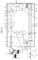
- FIG. 1 shows a device for noise detection 1 according to the invention in a block diagram.
- Various noise sources such as a car 2 , a locomotive 3 and a chirping bird 4, can be seen in this illustration.
- the acoustic signal picked up by all these noise sources by means of a microphone 5 is first fed in the device 1 to a so-called A-filter 6 , which, on the one hand, only allows the audible range of preferably 16 Hz - 16 KHz to pass from the frequency spectrum of the signal and thereby subjecting the signal to a so-called A-weighting, which it evaluates according to the different subjective human perceptions for different frequencies.
- A-filter 6 which, on the one hand, only allows the audible range of preferably 16 Hz - 16 KHz to pass from the frequency spectrum of the signal and thereby subjecting the signal to a so-called A-weighting, which it evaluates according to the different subjective human perceptions for different frequencies.
- A-weighting which it evaluates according to the different subjective human perceptions for different frequencies.
- the signal is now fed from the A filter 6 to a spectrum analysis device 7 , which uses a Fast Fourier Transformation to split the signal into a number n different levels (P) 8 for the n frequency bands.
- HEL background noise elimination device
- HEM background noise detection device
- the background noise elimination device (HEL) 9 now subtracts the background noise levels (H) 9 from the levels (P) 8 and outputs the result as a corrected level (K) 12 again.
- the corrected levels (K) 12 are fed to the renormalization device (REN) 13 , which renormalizes them and outputs them again as reformed intensities (R) 14 .
- the renormalized intensities (R) 14 are in turn fed to a differentiating device (DIFF) 15 , which they derive according to the time and then form the absolute amount from the result.
- DIFF differentiating device
- the result of differentiated renormalized intensities (dR) 16b obtained from this is then output again and, together with the renormalized intensities (R) 16a, forms the signal vector 16 .
- the signal vector 16 then serves both the pre-detection device (VOR) 17 and the neural network (NNN) for signal classification 18 as an input variable.
- VOR pre-detection device
- NNN neural network
- the pre-detection device (VOR) 17 now determines from this whether it is a whistle tone, a tone or no tone and accordingly outputs the pre-recognition signals tone 19 , whistle tone 20 or no tone 21 .
- the neural network (NNN) for signal classification 18 classifies the acoustic signal with the aid of the signal vector 16 and generates various classification signals 22 which classify the acoustic signal according to its frequency spectrum and / or its change over time.
- the classification signals 22 are fed to a reclassification device (UMK) 23 which combines them into three groups of noise classes and generates one of three noise class signals 24 according to the association of a classification signal with these groups.
- ULK reclassification device
- the noise class signals 24 , as well as the prerecognition signals 19 , 20 are fed to a marking device (MAR) 25 , which thus marks the level received by the A filter 6 in accordance with these signals 19 , 20 , 24 .
- This marking can then be represented, for example, as a different colored representation of the A-weighted level which has left the A-filter 6 .
- a pulse detection device (IDET) 26 is also arranged in front of the marking device (MAR) 25 , which also receives the level output by the A filter 6 and tests for the presence of a pulse. If such a pulse is present, it outputs a pulse detection signal 27 for this time, which is also fed to the marking device (MAR) 25 .
- the marking device (MAR) 25 thus marks the level received by the A filter 6 primarily over the markings caused by the noise class signals 24 or prerecognition signals 19 , 20 .
- the marked level signal 28 is finally output by the marking device (MAR) 25 and can then be displayed, for example, on a display 29 in accordance with the amplitude of its respective level and its marking.
- MAR marking device
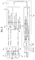
- the signal vector 16 which is composed of amplitudes 31 and absolute amounts based on the time of amplitudes 32 , is analyzed in its amplitude part 31 by a first maximum determining device 34 , which determining device 34 has both the maximum amplitude and the second largest amplitude of the n amplitudes (A 1 ... A n ) 31 each generated as an output signal.
- a second maximum detection apparatus 33 analyzes the absolute values of the derivative with respect to time n amplitude (dA dA 1 ... n) 32 and outputs the maximum thereof.
- the maxima determined in this way are now fed to the pre-detection device 17 , which is designed here as fuzzy logic, the maximum amplitude from the plurality of amplitudes 32 being fed to a first fuzzification device (fuzzy max A1 ) 30 as a receiving means of the device 17 .
- the second largest amplitude from the plurality of amplitudes 31 is fed to a second fuzzification device (fuzzy max A2 ) 35 as a receiving means.
- the absolute amount of the maximum time-derived amplitude from the plurality of time-derived n amplitudes (dA 1 ... dA n ) 32 is fed to a third fuzzification device (fuzzy max dA ) 36 as a receiving means.
- the fuzzification devices map the received amplitudes or the received absolute amount of an amplitude derived over time by means of membership functions according to the degree of their affiliation to a specific fuzzy set on linguistic variable 37 .
- the choice of the course of the corresponding membership functions is to be determined experimentally in accordance with the respective task.
- FIG. 3 shows a schematic overview of a wind power plant with surrounding residential buildings 39 .
- the wind power plant consists of wind turbines 40 , which represent the sound sources of the wind power plant, and a measuring station at a measuring location 41 , shown here by means of a microphone, with which measurements are taken at the measuring location 41 .
- the measurement signal is fed to a device according to the invention for measuring the sound level of wind turbines 42 , which now makes it possible to first determine the sound level of the sound source 40 in question without interference and background noise at the measurement location 41 .
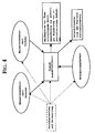
- FIG. 4 shows a schematic overview of the construction of a noise monitoring system according to the invention, as is suitable, for example, for monitoring port facilities. It is based on the networking of so-called emission and immission measurement units.
Landscapes
- Engineering & Computer Science (AREA)
- Physics & Mathematics (AREA)
- Multimedia (AREA)
- Acoustics & Sound (AREA)
- Health & Medical Sciences (AREA)
- Audiology, Speech & Language Pathology (AREA)
- Human Computer Interaction (AREA)
- Sustainable Energy (AREA)
- Combustion & Propulsion (AREA)
- General Engineering & Computer Science (AREA)
- Mechanical Engineering (AREA)
- Chemical & Material Sciences (AREA)
- Computational Linguistics (AREA)
- Life Sciences & Earth Sciences (AREA)
- Sustainable Development (AREA)
- Evolutionary Computation (AREA)
- Artificial Intelligence (AREA)
- Signal Processing (AREA)
- General Physics & Mathematics (AREA)
- Quality & Reliability (AREA)
- Measurement Of Mechanical Vibrations Or Ultrasonic Waves (AREA)
- Transplanting Machines (AREA)
- Burglar Alarm Systems (AREA)
Abstract
Description

- Straßen- und Schienenlärm aufgrund der Regelungen in der 16. Verordnung zum Bundesimmissionsschutzgesetz
- Fluglärm aufgrund des Fluglärmschutzgesetzes
- Gewerbelärm aufgrund der TA Lärm
- Sportlärm aufgrund der Regelungen in der 18. Verordnung zum Bundesimmissionsschutzgesetz
- Freizeitlärm aufgrund länderrechtlicher Regelungen, (vgl. etwa die Muster Verwaltungs Verordnung zur TA Lärm)
- Geräusche aus der Natur, die Fremdgeräusche i.S. der vorstehend angeführten Regelungen darstellen


- Wahrscheinlichste Geräuschquelle
- Position der Quelle
- Pegelhöhe der Schallimmission
- Datum und Uhrzeit
- einen Alarmtext
- Fig. 1
- eine erfindungsgemäße Vorrichtung zur Geräuscherkennung im Blockschaltbild,
- Fig. 2
- eine Vorerkennungseinrichtung als Fuzzy-Logic ausgeführt gleichfalls im Blockschaltbild,
- Fig. 3
- eine schematische Übersichtsdarstellung einer Windkraftanlage mit umgebender Wohnbebauung, und
- Fig. 4
- den Aufbau eines erfindungsgemäßen Lärmüberwachungssystems in schematischer Übersicht.
Claims (30)
- Vorrichtung zur Geräuscherkennung in akustischen Signalen (1) mit zumindesteiner Renormierungseinrichtung (13),die Mittel vorsieht, die jeweils zum Empfang der Amplitude (12, 31) eines bestimmten Frequenzbandes aus dem Frequenzspektrum des akustischen Signals dienen,sowie Mittel, die diese Amplitude oder Amplituden (12, 31) so renormiert oder renormieren, daß nach der Renormierung die Amplituden nur noch in ihren relativen Verhältnissen zueinander vorliegen undweiterhin einer Differenzierungseinrichtung (15),die Mittel vorsieht, die die renormierte Amplitude oder reformierten Amplituden (14, 31) nach der Zeit zumindest einfach ableitet oder ableiten oderdie die renormierte Amplitude oder reformierten Amplituden (14, 31) nach der Zeit zumindest einfach ableitet oder ableiten und hernach aus der nach der Zeit abgeleiteten Amplitude oder den nach der Zeit abgeleiteten Amplituden (16b, 32) den jeweiligen Absolutbetrag (ohne negatives Vorzeichen) bilden, sowie miteinem neuronalen Netzwerk (18) mitwobei das Klassifikationssignal oder die Klassifikationssignale Aufschluß über die Art des akustischen Signals gibt oder geben.Eingangsneuronen, Ausgangsneuronen und mit Gewichten versehenen Verbindungen zwischen den Neuronen,
wobei die Eingangsneuronen, jeweils zum Empfang der renormierten und nach der Zeit abgeleiteten Amplitude (16b, 32) eines bestimmten Frequenzbandes aus dem Frequenzspektrum des akustischen Signals oder deren jeweiligen Absolutbetrages vorgesehen sind, unddie Ausgangsneuronen zumindest ein Klassifikations-Signal (22) erzeugen, welches das akustische Signal entsprechend seinem Frequenzspektrum klassifiziert, - Vorrichtung zur Geräuscherkennung in akustischen Signalen nach Anspruch 1, dadurch gekennzeichnet, daß die Renormierungseinrichtung (13) die Amplitude oder Amplituden (12, 31) so renormiert, daß nach der Renormierung die Amplituden nur noch in ihren relativen Verhältnissen zueinander vorliegen wobei die Summe aller Amplituden (14, 31) nach der Renormierung gleich einer Konstante ist und die Amplituden (14, 31) je paarweise vor der Renormierung im gleichen Verhältnis zueinander stehen wie nach der Renormierung.
- Vorrichtung zur Geräuscherkennung in akustischen Signalen nach Anspruch 2, dadurch gekennzeichnet, daß die Konstante als die Zahl Eins gewählt wird.
- Vorrichtung zur Geräuscherkennung in akustischen Signalen nach einem der Ansprüche 1 bis 3, dadurch gekennzeichnet, daß das neuronale Netzwerk (18) auch Eingangsneuronen aufweist, die jeweils zum Empfang der Amplitude (12, 31) oder der reformierten Amplitude (14, 16a, 31) eines bestimmten Frequenzbandes aus dem Frequenzspektrum des akustischen Signals vorgesehen sind.
- Vorrichtung zur Geräuscherkennung in akustischen Signalen nach Anspruch 4, dadurch gekennzeichnet, daß sie weiterhin eine Vorerkennungseinrichtung (17) aufweist,die wiederum Mittel vorsieht, die jeweils zum Empfang der Amplitude (31) eines bestimmten Frequenzbandes aus dem Frequenzspektrum des akustischen Signals dienen,sowie Mittel, die jeweils zum Empfang der nach der Zeit abgeleiteten Amplitude (32) eines bestimmten Frequenzbandes aus dem Frequenzspektrum des akustischen Signals oder deren Absolutbetrages dienen,
wobei die Vorerkennungseinrichtung zumindest ein Vorerkennungssignal (19, 20, 21) erzeugt, welches das akustische Signal nach den Kategorien Ton (19), Pfeifton (20) und Kein-Ton (21) klassifiziert, und so weiteren Aufschluß über die Art des akustischen Signals gibt,und das neuronale Netz von zumindest einem der Vorerkennungssignale aktiviert wird, wenn das akustische Signal von der Vorerkennungseinrichtung als ein solches der Kategorie Kein-Ton (21) klassifiziert wurde. - Vorrichtung zur Geräuscherkennung in akustischen Signalen nach Anspruch 5, dadurch gekennzeichnet, daß von der Vorerkennungseinrichtung immer dann ein Vorerkennungssignal erzeugt wird, welches das akustische Signal nach der Kategorie Ton (19) klassifiziert, wenn mindestens eine Amplitude eines bestimmten Frequenzbandes aus dem Frequenzspektrum des akustischen Signals oberhalb eines vorgewählten Tonschwellwertes liegt.
- Vorrichtung zur Geräuscherkennung in akustischen Signalen nach Anspruch 5 oder 6, dadurch gekennzeichnet, daß von der Vorerkennungseinrichtung immer dann ein Vorerkennungssignal erzeugt wird, welches das akustische Signal nach der Kategorie Pfeifton (20) klassifiziert, wenn mindestens eine nach der Zeit abgeleitete Amplitude eines bestimmten Frequenzbandes aus dem Frequenzspektrum des akustischen Signals oder deren Absolutbetrag oberhalb eines vorgewählten Pfeiftonschwellwertes liegt.
- Vorrichtung zur Geräuscherkennung in akustischen Signalen nach Anspruch 5, dadurch gekennzeichnet, daß von der Vorerkennungseinrichtung immer dann ein Vorerkennungssignal erzeugt wird, welches das akustische Signal nach der Kategorie Ton (19) klassifiziert, wenn mindestens eine Amplitude eines bestimmten Frequenzbandes aus dem Frequenzspektrum des akustischen Signals oberhalb eines vorgewählten Tonschwellwertes liegtund immer dann ein Vorerkennungssignal erzeugt wird, welches das akustische Signal nach der Kategorie Pfeifton (20) klassifiziert, wenn mindestens eine nach der Zeit abgeleitete Amplitude eines bestimmten Frequenzbandes aus dem Frequenzspektrum des akustischen Signals oder deren Absolutbetrag oberhalb als eines vorgewählten Pfeiftonschwellwertes liegtund immer dann ein Vorerkennungssignal erzeugt wird, welches das akustische Signal nach der Kategorie Kein-Ton (21) klassifiziert, wenn das akustische Signal weder nach der Kategorie Ton noch nach der Kategorie Pfeifton klassifiziert wird.
- Vorrichtung zur Geräuscherkennung in akustischen Signalen nach Anspruch 5, dadurch gekennzeichnet, daß als Vorerkennungsvorrichtung (17) eine Fuzzy-Logic vorgesehen ist, diewiederum Mittel (30, 35) vorsieht, die jeweils zum Empfang der Amplitude eines bestimmten Frequenzbandes aus dem Frequenzspektrum des akustischen Signals dienen,sowie Mittel (36), die jeweils zum Empfang der nach der Zeit abgeleiteten Amplitude eines bestimmten Frequenzbandes aus dem Frequenzspektrum des akustischen Signals oder deren Absolutbetrages dienen,
wobei die so empfangenen Amplituden (31) oder abgeleiteten Amplituden bzw. deren Absolutbeträge (32) jeweils fuzzyfiziert, d.h. entsprechend einer Zugehörigkeitsfunktion auf linguistische Variable (37) abgebildet werden, unddie Fuzzy-Logic mittels einer Inferenzmaschine die so fuzzyfizierten Amplituden (31) und/oder nach der Zeit abgeleiteten Amplituden (32) oder deren Absolutbetrag mittels in einer Wissensbasis hinterlegter Regeln (38) zu zumindest einem Vorerkennungssignal (19, 20, 21) inferiert, welches oder welche das akustische Signal nach den Kategorien Ton, Pfeifton und Kein-Ton klassifiziert oder klassifizieren, und so Aufschluß über die Art des akustischen Signals gibt oder geben. - Vorrichtung zur Geräuscherkennung in akustischen Signalen nach Anspruch 9, dadurch gekennzeichnet, daß als Vorerkennungsvorrichtung (17) eine Fuzzy-Logic vorgesehen ist, diewiederum Mittel (30, 35) vorsieht, die zum Empfang der maximalen Amplitude aus einer Vielzahl von, zu bestimmten Frequenzbändern gehörigen Amplituden aus dem Frequenzspektrum des akustischen Signals dienen, undweiterhin zum Empfang der zweitgrößten Amplitude aus einer Vielzahl von, zu bestimmten Frequenzbändern gehörigen, Amplituden aus dem Frequenzspektrum des akustischen Signals dienen,sowie Mittel (36), die zum Empfang der maximalen nach der Zeit abgeleiteten Amplitude oder deren Absolutbetrags aus einer Vielzahl von, zu bestimmten Frequenzbändern gehörigen abgeleiten Amplituden oder deren Absolutbeträge aus dem Frequenzspektrum des akustischen Signals dienen,
wobei die so empfangenen Amplituden (31) oder abgeleiteten Amplituden (32) bzw. deren Absolutbeträge jeweils fuzzyfiziert, d.h. entsprechend einer Zugehörigkeitsfunktion auf linguistische Variable (37) abgebildet werden, unddie Fuzzy-Logic mittels einer Inferenzmaschine die so fuzzyfizierten Amplituden und/oder nach der Zeit abgeleiteten Amplituden (32) oder deren Absolutbetrag mittels in einer Wissensbasis hinterlegter Regeln (38) zu zumindest einem Vorerkennungssignal (19, 20, 21) inferiert, welches oder welche das akustische Signal nach den Kategorien Ton, Pfeifton und Kein-Ton klassifiziert oder klassifizieren, und so Aufschluß über die Art des akustischen Signals gibt oder geben. - Vorrichtung zur Geräuscherkennung in akustischen Signalen nach einem der Ansprüche 1 bis 10, dadurch gekennzeichnet, daß die Vorrichtung weiterhin eine Vorrichtung zur Hintergrundgeräuschermittlung (10) in akustischen Signalen aufweist, die jeweils die Hintergrundgeräusch-Amplitude (11) eines bestimmten Frequenzbandes aus dem Frequenzspektrum des zum akustischen Signal gehörigen jeweiligen Hintergrundgeräusches ermittelt, wobei sieMittel aufweist, die jeweils zum Empfang der jeweils aktuell gemessenen Amplitude (31) eines bestimmten Frequenzbandes aus dem Frequenzspektrum des akustischen Signals dienen, unddie Hintergrundgeräuschermittlung ausgehend von einer zu Betriebsbeginn hoch gewählten fiktiven Start-Hintergrundgeräusch-Amplitude derart geschieht, daß die jeweilige Hintergrundgeräusch-Amplitude (11) jeweils nach einer von Zeit zu Zeit erfolgenden Messung der aktuell herrschenden Amplitude (31) des zugehörigen Frequenzbandes immer dann auf den letzten Meßwert korrigiert wird, wenn dieser Meßwert kleiner als der Wert der bis zu diesem Zeitpunkt solchermaßen ermittelten Hintergrundgeräusch-Amplitude (11) war, undweiterhin Ausgabemittel vorgesehen sind, die die ermittelten Hintergrundgeräusch-Amplituden (11) eines bestimmten Frequenzbandes aus dem Frequenzspektrum des akustischen Signals ausgeben.
- Vorrichtung zur Geräuscherkennung in akustischen Signalen nach einem der Ansprüche 1 bis 10, dadurch gekennzeichnet, daß die Vorrichtung weiterhin eine Vorrichtung zur Hintergrundgeräuschermittlung (10) in akustischen Signalen aufweist, die jeweils die Hintergrundgeräusch-Amplitude (11) eines bestimmten Frequenzbandes aus dem Frequenzspektrum des zum akustischen Signal gehörigen jeweiligen Hintergrundgeräusches ermittelt, wobei sieMittel aufweist, die jeweils zum Empfang der jeweils aktuell gemessenen Amplitude (31) eines bestimmten Frequenzbandes aus dem Frequenzspektrum des akustischen Signals dienen, unddie Hintergrundgeräuschermittlung ausgehend von einer zu Betriebsbeginn hoch gewählten fiktiven Start-Hintergrundgeräusch-Amplitude derart geschieht, daß die jeweilige Hintergrundgeräusch-Amplitude (11) jeweils nach einer von Zeit zu Zeit erfolgenden Messung der aktuell herrschenden Amplitude (31) des zugehörigen Frequenzbandes immer dann auf den letzten Meßwert korrigiert wird, wenn dieser Meßwert kleiner als der Wert der bis zu diesem Zeitpunkt ermittelten Hintergrundgeräusch-Amplitude (11) zuzüglich eines bestimmten konstanten Aufschlages war, undweiterhin Ausgabemittel vorgesehen sind, die die ermittelten HintergrundgeräuschAmplituden (11) eines bestimmten Frequenzbandes aus dem Frequenzspektrum des akustischen Signals ausgeben.
- Vorrichtung zur Geräuscherkennung in akustischen Signalen nach Anspruch 11 oder 12, dadurch gekennzeichnet, daß die Vorrichtung zur Hintergrundgeräuschermittlung in akustischen Signalen (10) vor jeder von Zeit zu Zeit erfolgenden Messung der aktuell herrschenden Amplitude (31) die jeweilige bis zu diesem Zeitpunkt ermittelte Hintergrundgeräusch-Amplitude (11) um einen bestimmten festen Zuschlag erhöht.
- Vorrichtung zur Geräuscherkennung in akustischen Signalen nach Anspruch 11, 12 oder 13, dadurch gekennzeichnet, daß sie weiterhin eine Hintergrundgeräusch-Eliminationseinrichtung (9) aufweist,die wiederum Mittel vorsieht, die jeweils zum Empfang der Amplitude (31) eines bestimmten Frequenzbandes aus dem Frequenzspektrum des akustischen Signals dienen,sowie Mittel, die jeweils zum Empfang der Hintergrundgeräusch-Amplitude (11) eines bestimmten Frequenzbandes aus dem Frequenzspektrum des zum akustischen Signal gehörigen jeweiligen Hintergrundgeräusches dienen,und Mittel, die von der jeweiligen Amplitude (31) eines bestimmten Frequenzbandes aus dem Frequenzspektrum des akustischen Signals die Hintergrundgeräusch-Amplitude (11) des entsprechenden Frequenzbandes aus dem Frequenzspektrum des zum akustischen Signal gehörigen jeweiligen Hintergrundgeräusches zum Abzug bringen,weiterhin Ausgabemittel, die die vom Hintergrundgeräusch solchermaßen befreite Amplitude oder befreiten Amplituden (12) eines bestimmten Frequenzbandes aus dem Frequenzspektrum des akustischen Signals ausgeben.
- Vorrichtung zur Geräuscherkennung in akustischen Signalen nach einem der Ansprüche 1 bis 14, dadurch gekennzeichnet, daß sie weiterhin eine Umklassifizierungsvorrichtung (23) aufweist, welche Mittel zum Empfang der jeweiligen Klassifikationssignale (22) und/oder jeweiligen Vorerkennungssignale aufweist, wobei die Umklassifizierungsvorrichtung (23) zumindest ein Geräuschklassensignal (24) hieraus erzeugt und ausgibt, welches das akustische Signal einer oder mehreren Geräuschkategorien zuordnet.
- Vorrichtung zur Messung des Schallpegels von Windkraftanlagen (42), dadurch gekennzeichnet, daß diese eine Vorrichtung zur Geräuscherkennung in akustischen Signalen (1) nach einem der Ansprüche 1 bis 15 aufweist, welche ein der Umgebung von Windkraftanlagen entstammendes akustisches Signal auswertet und deren Ausgangsneuronen zumindest ein Klassifikations-Signal (22) erzeugen, welches oder welche über die Art des der Umgebung von Windkraftanlagen entstammenden akustischen Signals zumindest insoweit Aufschluß gibt oder geben, als daß das akustische Signal zumindest nach den Kategorien Windkraftanlagen-Schall einerseits und Kein-Windkraftanlagen-Schall andererseits klassifiziert wird, wobei das akustische Signal nur insoweit zur Messung des Schallpegels berücksichtigt wird, als es von der Vorrichtung zur Geräuscherkennung in akustischen Signalen als Windkraftanlagen-Schall klassifiziert wird.
- Vorrichtung zur Messung des Schallpegels von Windkraftanlagen (42) nach Anspruch 16, dadurch gekennzeichnet, daß die Ausgangsneuronen zumindest ein Klassifikations-Signal (22) erzeugen, welches oder welche über die Art des der Umgebung von Windkraftanlagen entstammenden akustischen Signals zumindest insoweit Aufschluß gibt oder geben, als daß das akustische Signal zumindest nach den Kategorien Windkraftanlagen-Schall einerseits und Wind-Schall-Tieffrequent oder Wind-Schall-Hochfrequent andererseits klassifiziert wird, wobei das akustische Signal nur insoweit zur Messung des Schallpegels berücksichtigt wird, als es von der Vorrichtung zur Geräuscherkennung in akustischen Signalen als Windkraftanlagen-Schall klassifiziert wird.
- Vorrichtung zur Messung des Schallpegels von Windkraftanlagen (42) nach Anspruch 16, insoweit dieser auf Ansprüche rückbezogen ist, nach denen die Vorrichtung zur Messung des Geräuschpegels von Windkraftanlagen eine Vorrichtung zur Geräuscherkennung in akustischen Signalen nach Anspruch 5 oder einem hierauf rückbezogenen Anspruch aufweist, dadurch gekennzeichnet, daß die Ausgangsneuronen zumindest ein Klassifikations-Signal (22) erzeugen, welches oder welche über die Art des der Umgebung von Windkraftanlagen entstammenden akustischen Signals insoweit Aufschluß gibt oder geben, als daß das akustische Signal zumindest nach den Kategorien Windkraftanlagen-Schall einerseits und Kein-Windkraftanlagen-Schall andererseits klassifiziert wird und die Vorerkennungsvorrichtung zumindest ein Vorerkennungssignal (19, 20, 21) erzeugt, welches das akustische Signal nach den Kategorien Ton, vorzugsweise Wind-Ton, Pfeifton, vorzugsweise Wind-Pfeifton, und Kein-Ton klassifiziert, wobei das akustische Signal nur insoweit zur Messung des Schallpegels berücksichtigt wird, als es von der Vorrichtung zur Geräuscherkennung in akustischen Signalen als Windkraftanlagen-Schall klassifiziert wird.
- Vorrichtung zur Messung des Schallpegels von Windkraftanlagen (42), dadurch gekennzeichnet, daß diese eine Vorrichtung zur Geräuscherkennung in akustischen Signalen nach Anspruch 15 oder einem hierauf rückbezogenen Anspruch aufweist, wobei diese Vorrichtung ein der Umgebung von Windkraftanlagen entstammendes akustisches Signal auswertet und die Umklassifizierungsvorrichtung zumindest ein Geräuschklassensignal (24) hieraus erzeugt, welches oder welche das akustische Signal zumindest als Windkraftanlagen-Schall oder Kein-Windkraftanlagen-Schall klassifiziert oder klassifizieren, wobei das akustische Signal nur insoweit zur Messung des Schallpegels berücksichtigt wird, als es von der Vorrichtung zur Geräuscherkennung in akustischen Signalen als Windkraftanlagen-Schall klassifiziert wird.
- Vorrichtung zur Messung des Schallpegels von Windkraftanlagen (42) nach einem der Ansprüche 16 bis 19, dadurch gekennzeichnet, daß eine Mittelungsvorrichtung zur Mittelung, vorzugsweise langfristigen Mittelung des während des Betriebes der Windkraftanlage gemessenen Geräuschpegels vorgesehen ist, wobei nur solche während des Betriebes der Windkraftanlage gemessenen Pegel von der Mittelungsvorrichtung zur Bildung des Mittels berücksichtigt werden, die von einem akustischen Signal herrühren, welches von der Vorrichtung zur Geräuscherkennung in akustischen Signalen als Windkraftanklagen-Schall klassifiziert wurde.
- Vorrichtung zur Messung des Schallpegels von Windkraftanlagen (42) nach Anspruch 20, dadurch gekennzeichnet, daß weiterhin eine Überwachungsvorrichtung vorgesehen ist, die die gleitende Mittelung des während des Betriebes der Windkraftanlage gemessenen Schallpegels auf die Überschreitung eines Grenzwertes hin überwacht.
- Lärmüberwachungsvorrichtung zur Messung des Schallpegels von Lärmemmissionsgebieten, insbesondere Gewerbegelärmgebieten, dadurch gekennzeichnet, daß diese eine Vorrichtung zur Geräuscherkennung in akustischen Signalen (1) nach einem der Ansprüche 1 bis 15 aufweist, welche ein in einem Immissionsbereich, vorzugsweise in einem zu dem zu überwachenden Lärmemmisionsgebiet angrenzenden Gebiet, gemessenes akustisches Signal auswertet und deren Ausgangsneuronen zumindest ein Klassifikations-Signal (22) erzeugen, welches oder welche über die Art des akustischen Signals zumindest insoweit Aufschluß gibt oder geben, als daß das akustische Signal zumindest nach den Kategorien Lärmemmissionsgebietschall einerseits und Kein-Lärmemmissionsgebietschall andererseits klassifiziert wird.
- Lärmüberwachungsvorrichtung zur Messung des Schallpegels von Lärmemmissionsgebieten, insbesondere Gewerbegelärmgebieten, dadurch gekennzeichnet, daß diese eine Vorrichtung zur Geräuscherkennung in akustischen Signalen nach Anspruch 15 oder einem hierauf rückbezogenen Anspruch aufweist, wobei diese Vorrichtung ein in einem Immissionsbereich, vorzugsweise in einem zu dem zu überwachenden Lärmemmisionsgebiet angrenzenden Gebiet, gemessenes akustisches Signal auswertet und die Umklassifizierungsvorrichtung zumindest ein Geräuschklassensignal (24) hieraus erzeugt, welches oder welche das akustische Signal zumindest als Lärmemmissionsgebietschall oder Kein-Lärmemmissionsgebietschall klassifiziert oder klassifizieren.
- Lärmüberwachungsvorrichtung zur Messung des Schallpegels von Lärmemmissionsgebieten nach Anspruch 22 oder 23, dadurch gekennzeichnet, daß das akustische Signal nur insoweit zur Messung des Schallpegels berücksichtigt wird, als es von der Vorrichtung zur Geräuscherkennung in akustischen Signalen als Lärmemmissionsgebietschall klassifiziert wird.
- Lärmüberwachungsvorrichtung zur Messung des Schallpegels von Lärmemmissionsgebieten nach Anspruch 22, 23 oder 24, dadurch gekennzeichnet, daß weiterhin auch eine Vorrichtung zur Geräuscherkennung in akustischen Signalen (1) nach einem der Ansprüche 1 bis 15 vorgesehen ist, welche ein im zu überwachenden Lärmemmisionsgebiet gemessenes akustisches Signal auswertet und deren Ausgangsneuronen zumindest ein Klassifikations-Signal (22) erzeugen, welches oder welche über die Art des akustischen Signals Aufschluß gibt oder geben und es somit klassifiziert oder klassifizieren.
- Lärmüberwachungsvorrichtung zur Messung des Schallpegels von Lärmemmissionsgebieten nach Anspruch 22, 23 oder 24, dadurch gekennzeichnet, daß diese weiterhin auch eine Vorrichtung zur Geräuscherkennung in akustischen Signalen nach Anspruch 15 oder einem hierauf rückbezogenen Anspruch aufweist, wobei diese Vorrichtung ein im zu überwachenden Lärmemmisionsgebiet gemessenes akustisches Signal auswertet und die Umklassifizierungsvorrichtung zumindest ein Geräuschklassensignal (24) hieraus erzeugt, welches oder welche das akustische Signal klassifiziert oder klassifizieren.
- Lärmüberwachungsvorrichtung zur Messung des Schallpegels von Lärmemmissionsgebieten nach Anspruch 25 oder 26, dadurch gekennzeichnet, daß zusätzlich eine zentrale Auswerteeinheit vorgesehen ist, welche mit der Immissionsmeßstelle und der Emmissionsmeßstelle verbunden ist, die eine Alarmmeldung auslöst, wenn ein Immissionsrichtwert überschritten wird oder eine solche Überschreitung droht, wobei die Alarmmeldung entsprechend dem aus der Auswertung des im Lärmemmisionsgebiet gemessenen akustischen Signals erzeugten Klassifikations-Signal oder Geräuschklassensignal einer hierzu gehörigen wahrscheinlichen Geräuschquelle zugeordnet wird.
- Verfahren zur Bestimmung des von Schallquellen (40) einer Windkraftanlage ausgehenden Schallpegels an einem frei wählbaren ersten Ort (Bestimmungsort) (39) mittels Messung des Schallpegels an einem zweiten Ort (Meßort) (41) mit einer Vorrichtung (42) nach einem der Ansprüche 16 bis 21, wobei der Abstand zwischen der jeweiligen Schallquelle (40) und dem Meßort (41), der Abstand zwischen der jeweiligen Schallquelle (40) und dem Bestimmungsort (39), die Höhe der jeweiligen Schallquelle (40), die Höhe des Meßorts(41), die Höhe des Bestimmungsortes (39), die Windgeschwindigkeit, die Windrichtung, die Luftfeuchte, die Temperatur, der Winkel zwischen der Windrichtung und der direkten Verbindungsstrecke von der jeweiligen Schallquelle (40) zum Meßort (41), der Winkel zwischen der Windrichtung und der direkten Verbindungsstrecke von der jeweiligen Schallquelle (40) zum Bestimmungsort (39), der Stabilitätsfaktor und der meteorologische Temperaturgradient bestimmt werden und hieraus dann der Schallpegel am Bestimmungsort (39) bestimmt wird.
- Verfahren zur Prognose des von einer Windkraftanlage herrührenden gemittelten, vorzugsweise langfristig gemittelten Schallpegels an einem frei wählbaren Prognose-Ort (39) während eines Prognosezeitraumes, wobei dies auf der Grundlage einer Messung des Schallpegels an einem zweiten Ort (Meßort) (41) mit einer Vorrichtung (42) nach einem der Ansprüche 16 bis 21 und einem Prognosemodell mit Annahmen über die Entwicklung von Windgeschwindigkeit, Windrichtung, Luftfeuchte, Temperatur, Stabilitätsfaktor und meteorologischen Temperaturgradienten während des Prognosezeitraumes geschieht, indem über den Prognosezeitraum hinweg der zeitliche Verlauf des am Prognose-Ort (39) zu erwartenden gemittelten, vorzugsweise langfristig gemittelten Schallpegels nach dem Verfahren nach Anspruch 28 ermittelt wird, wobei die dortigen zu bestimmenden Größen für Windgeschwindigkeit, Windrichtung, Luftfeuchte, Temperatur, Stabilitätsfaktor und meteorologischen Temperaturgradienten nicht bestimmt, sondern stattdessen dem Prognosemodell für den Prognosezeitraum entnommen werden.
- Verfahren zur Optimierung des Betriebes einer Windkraftanlage, wobei für einen oder mehrere frei wählbare Orte (Prognose-Orte) (39) eine oder mehrere Annahmen über Betriebszeiträume der einzelnen Schallquellen (40) der Windkraftanlage (Windräder) während des Prognosezeitraumes gemacht werden und basierend hierauf die jeweils zu erwartende gemittelte, vorzugsweise langfristig gemittelte Entwicklung des Schallpegels an den Prognose-Orten (39) nach dem Verfahren nach Anspruch 29 prognostiziert werden, und dann schließlich die Betriebszeiträume der einzelnen Schallquellen (40) der Windkraftanlage (Windräder) für den tatsächlichen Betrieb während des Prognosezeitraumes festgelegt werden, welche bei größtmöglicher Energieproduktion durch die Windkraftanlage noch unterhalb eines nicht zu überschreitenden Grenzwertes für den gemittelten, vorzugsweise langfristig gemittelten Schallpegels an den jeweiligen Prognose-Orten (39) liegen.
Applications Claiming Priority (4)
| Application Number | Priority Date | Filing Date | Title |
|---|---|---|---|
| DE19949637 | 1999-10-14 | ||
| DE19949637A DE19949637A1 (de) | 1999-10-14 | 1999-10-14 | Verfahren und Vorrichtungen zur Geräuscherkennung und -trennung sowie Lärmüberwachung und -prognose |
| DE20001263 | 2000-01-26 | ||
| DE20001263U | 2000-01-26 |
Publications (3)
| Publication Number | Publication Date |
|---|---|
| EP1092964A2 true EP1092964A2 (de) | 2001-04-18 |
| EP1092964A3 EP1092964A3 (de) | 2004-09-01 |
| EP1092964B1 EP1092964B1 (de) | 2007-12-12 |
Family
ID=26055277
Family Applications (1)
| Application Number | Title | Priority Date | Filing Date |
|---|---|---|---|
| EP00121263A Expired - Lifetime EP1092964B1 (de) | 1999-10-14 | 2000-10-05 | Vorrichtung zur Geräuscherkennung und Geräuschtrennung |
Country Status (3)
| Country | Link |
|---|---|
| EP (1) | EP1092964B1 (de) |
| AT (1) | ATE381001T1 (de) |
| DE (2) | DE20016999U1 (de) |
Cited By (5)
| Publication number | Priority date | Publication date | Assignee | Title |
|---|---|---|---|---|
| WO2003064853A1 (en) * | 2002-01-29 | 2003-08-07 | Abb Ab | Apparatus and method for operation of a power generating plant |
| CN102852719A (zh) * | 2011-06-30 | 2013-01-02 | 通用电气公司 | 控制风力涡轮机噪声幅度调制的系统和方法 |
| DE102013111784B4 (de) * | 2013-10-25 | 2019-11-14 | Intel IP Corporation | Audioverarbeitungsvorrichtungen und audioverarbeitungsverfahren |
| CN111613237A (zh) * | 2020-04-26 | 2020-09-01 | 深圳市艾特智能科技有限公司 | 一种音频处理方法 |
| WO2021209726A1 (fr) * | 2020-04-16 | 2021-10-21 | Intrapreneuriat Bouygues | Système de reconnaissance et d'identification de sources sonores en temps réel |
Families Citing this family (9)
| Publication number | Priority date | Publication date | Assignee | Title |
|---|---|---|---|---|
| US20070031237A1 (en) * | 2005-07-29 | 2007-02-08 | General Electric Company | Method and apparatus for producing wind energy with reduced wind turbine noise |
| US8043054B2 (en) | 2010-08-25 | 2011-10-25 | General Electric Company | Method and system for monitoring wind turbine |
| US10249305B2 (en) | 2016-05-19 | 2019-04-02 | Microsoft Technology Licensing, Llc | Permutation invariant training for talker-independent multi-talker speech separation |
| ES2695924A1 (es) * | 2017-07-10 | 2019-01-11 | Univ Jaen | Procedimiento para la obtención de un indicador de ruido acústico |
| US10957337B2 (en) | 2018-04-11 | 2021-03-23 | Microsoft Technology Licensing, Llc | Multi-microphone speech separation |
| DE102020110659A1 (de) | 2020-04-20 | 2021-10-21 | Bayerische Motoren Werke Aktiengesellschaft | Betreiben eines Fahrzeugs sowie Fahrzeug und System |
| DE102022003089A1 (de) | 2022-08-23 | 2024-02-29 | Mercedes-Benz Group AG | Signalausgabevorrichtung und Kraftfahrzeug mit einer solchen Signalausgabevorrichtung |
| DE102023212390A1 (de) | 2023-12-08 | 2025-06-12 | Robert Bosch Gesellschaft mit beschränkter Haftung | Verfahren zur akustischen Überwachung eines Rotorblatts einer Windenergieanlage und akustisch überwachte Windenergieanlage |
| DE102023212392A1 (de) | 2023-12-08 | 2025-06-12 | Robert Bosch Gesellschaft mit beschränkter Haftung | Verfahren und Vorrichtung zur akustischen Überwachung eines Windparks und akustisch überwachter Windpark |
Family Cites Families (2)
| Publication number | Priority date | Publication date | Assignee | Title |
|---|---|---|---|---|
| US5501105A (en) * | 1991-10-02 | 1996-03-26 | Monitoring Technology Corp. | Digital signal processing of encoder signals to detect resonances in rotating machines |
| US5619616A (en) * | 1994-04-25 | 1997-04-08 | Minnesota Mining And Manufacturing Company | Vehicle classification system using a passive audio input to a neural network |
-
2000
- 2000-10-04 DE DE20016999U patent/DE20016999U1/de not_active Expired - Lifetime
- 2000-10-05 AT AT00121263T patent/ATE381001T1/de not_active IP Right Cessation
- 2000-10-05 EP EP00121263A patent/EP1092964B1/de not_active Expired - Lifetime
- 2000-10-05 DE DE50014840T patent/DE50014840D1/de not_active Expired - Lifetime
Cited By (7)
| Publication number | Priority date | Publication date | Assignee | Title |
|---|---|---|---|---|
| WO2003064853A1 (en) * | 2002-01-29 | 2003-08-07 | Abb Ab | Apparatus and method for operation of a power generating plant |
| CN102852719A (zh) * | 2011-06-30 | 2013-01-02 | 通用电气公司 | 控制风力涡轮机噪声幅度调制的系统和方法 |
| DE102013111784B4 (de) * | 2013-10-25 | 2019-11-14 | Intel IP Corporation | Audioverarbeitungsvorrichtungen und audioverarbeitungsverfahren |
| WO2021209726A1 (fr) * | 2020-04-16 | 2021-10-21 | Intrapreneuriat Bouygues | Système de reconnaissance et d'identification de sources sonores en temps réel |
| FR3109458A1 (fr) * | 2020-04-16 | 2021-10-22 | Intrapreneuriat Bouygues | Système de reconnaissance et d'identification de sources sonores en temps réel |
| US12574681B2 (en) | 2020-04-16 | 2026-03-10 | Uby | System for real-time recognition and identification of sound sources |
| CN111613237A (zh) * | 2020-04-26 | 2020-09-01 | 深圳市艾特智能科技有限公司 | 一种音频处理方法 |
Also Published As
| Publication number | Publication date |
|---|---|
| DE50014840D1 (de) | 2008-01-24 |
| ATE381001T1 (de) | 2007-12-15 |
| DE20016999U1 (de) | 2001-01-25 |
| EP1092964A3 (de) | 2004-09-01 |
| EP1092964B1 (de) | 2007-12-12 |
Similar Documents
| Publication | Publication Date | Title |
|---|---|---|
| EP1092964B1 (de) | Vorrichtung zur Geräuscherkennung und Geräuschtrennung | |
| DE69934632T3 (de) | Dynamisches, multiattributes Gefahrenpriorisierungssystem für ein Flugzeug | |
| EP0986912B1 (de) | Verfahren zum überwachen eines vorgegebenen überwachungsbereiches | |
| DE10354322B4 (de) | Verfahren und System zur Ermittlung der Fahrsituation | |
| DE102008007149B4 (de) | Verfahren und Vorrichtung zum Erzeugen, Steuern und Auslösen eines Warnsignals in einem Kraftfahrzeug | |
| DE102019205543A1 (de) | Verfahren zum Klassifizieren zeitlich aufeinanderfolgender digitaler Audiodaten | |
| DE4207728A1 (de) | Verfahren zur qualitaetspruefung von pruefobjekten | |
| DE19949637A1 (de) | Verfahren und Vorrichtungen zur Geräuscherkennung und -trennung sowie Lärmüberwachung und -prognose | |
| DE102019213697B4 (de) | Verfahren zum Erkennen einer Annäherung und/oder Entfernung eines Einsatzfahrzeugs relativ zu einem Fahrzeug | |
| DE3929077C2 (de) | Verfahren und Einrichtung zur akustischen Identifikation und Klassifikation von Hubschraubern | |
| EP0750764B1 (de) | Verfahren und anordnung zur fuzzy-regelung | |
| WO2020259983A1 (de) | Raumüberwachungsverfahren und raumüberwachungsanlage zum überwachen eines verkehrsraumes | |
| DE3128578C2 (de) | ||
| DE102009048739B3 (de) | Verfahren und Vorrichtung zur automatischen Waldbranderkennung | |
| DE102013013869B4 (de) | Verfahren zum Betrieb eines Fahrerassistenzsystems zur Warnung vor zu großer Ablenkung und Kraftfahrzeug | |
| DE69726458T2 (de) | Vorichtung und verfahren zur analyse und zum filtern von geräuschen | |
| DE102021206618A1 (de) | Verfahren zur Erhöhung der Erkennungsgenauigkeit eines Überwachungssystems | |
| EP0891069B1 (de) | Erkennung eines betrügerischen Anrufs mittels eines neuronalen Netzes | |
| EP2792165A1 (de) | Anpassung einer klassifikation eines audiosignals in einem hörgerät | |
| EP0861447B1 (de) | Verfahren und vorrichtung zur detektion von fussgängern | |
| EP4012611B1 (de) | Bestimmung der für einen bildklassifikator entscheidungsrelevanten bildanteile durch zielgerichtetes abwandeln im latenten raum | |
| DE102022132797A1 (de) | Computerimplementiertes Verfahren zum Kalibrieren eines Aktivsystems | |
| EP4012175A1 (de) | Verfahren und vorrichtung zur vermeidung von kollisionen zwischen mindestens einem fliegenden vogel und einer windturbine | |
| DE19626329C2 (de) | Verfahren zur Analyse von Schallereignissen | |
| DE102023211501B3 (de) | Verfahren und Vorrichtung zum Bestimmen eines Signal-Rausch-Abstands eines Signals |
Legal Events
| Date | Code | Title | Description |
|---|---|---|---|
| PUAI | Public reference made under article 153(3) epc to a published international application that has entered the european phase |
Free format text: ORIGINAL CODE: 0009012 |
|
| AK | Designated contracting states |
Kind code of ref document: A2 Designated state(s): AT BE CH CY DE DK ES FI FR GB GR IE IT LI LU MC NL PT SE |
|
| AX | Request for extension of the european patent |
Free format text: AL;LT;LV;MK;RO;SI |
|
| PUAL | Search report despatched |
Free format text: ORIGINAL CODE: 0009013 |
|
| AK | Designated contracting states |
Kind code of ref document: A3 Designated state(s): AT BE CH CY DE DK ES FI FR GB GR IE IT LI LU MC NL PT SE |
|
| AX | Request for extension of the european patent |
Extension state: AL LT LV MK RO SI |
|
| RIC1 | Information provided on ipc code assigned before grant |
Ipc: 7G 01H 3/14 B Ipc: 7G 01H 3/08 A |
|
| 17P | Request for examination filed |
Effective date: 20050219 |
|
| AKX | Designation fees paid |
Designated state(s): AT BE CH CY DE DK ES FI FR GB GR IE IT LI LU MC NL PT SE |
|
| RAP1 | Party data changed (applicant data changed or rights of an application transferred) |
Owner name: KIWITZ, ANDRE Owner name: DEBAKOM, GESELLSCHAFT FUER SENSORISCHE MESSTECHNIK |
|
| RIN1 | Information on inventor provided before grant (corrected) |
Inventor name: KIWITZ, ANDRE Inventor name: DEBAKOM, GESELLSCHAFT FUER SENSORISCHE MESSTECHNIK |
|
| RIN1 | Information on inventor provided before grant (corrected) |
Inventor name: ANDRE KIWITZ Inventor name: DIETRICH KUEHNER |
|
| GRAP | Despatch of communication of intention to grant a patent |
Free format text: ORIGINAL CODE: EPIDOSNIGR1 |
|
| RTI1 | Title (correction) |
Free format text: APPARATUS FOR NOISE RECOGNITION AND NOISE SEPARATION |
|
| GRAS | Grant fee paid |
Free format text: ORIGINAL CODE: EPIDOSNIGR3 |
|
| GRAA | (expected) grant |
Free format text: ORIGINAL CODE: 0009210 |
|
| RAP1 | Party data changed (applicant data changed or rights of an application transferred) |
Owner name: DEBAKOM, GESELLSCHAFT FUER SENSORISCHE MESSTECHNIK Owner name: KIWITZ, ANDRE |
|
| AK | Designated contracting states |
Kind code of ref document: B1 Designated state(s): AT BE CH CY DE DK ES FI FR GB GR IE IT LI LU MC NL PT SE |
|
| REG | Reference to a national code |
Ref country code: GB Ref legal event code: FG4D Free format text: NOT ENGLISH |
|
| REG | Reference to a national code |
Ref country code: CH Ref legal event code: EP |
|
| REG | Reference to a national code |
Ref country code: IE Ref legal event code: FG4D Free format text: LANGUAGE OF EP DOCUMENT: GERMAN |
|
| REF | Corresponds to: |
Ref document number: 50014840 Country of ref document: DE Date of ref document: 20080124 Kind code of ref document: P |
|
| PG25 | Lapsed in a contracting state [announced via postgrant information from national office to epo] |
Ref country code: SE Free format text: LAPSE BECAUSE OF FAILURE TO SUBMIT A TRANSLATION OF THE DESCRIPTION OR TO PAY THE FEE WITHIN THE PRESCRIBED TIME-LIMIT Effective date: 20080312 |
|
| PG25 | Lapsed in a contracting state [announced via postgrant information from national office to epo] |
Ref country code: FI Free format text: LAPSE BECAUSE OF FAILURE TO SUBMIT A TRANSLATION OF THE DESCRIPTION OR TO PAY THE FEE WITHIN THE PRESCRIBED TIME-LIMIT Effective date: 20071212 Ref country code: NL Free format text: LAPSE BECAUSE OF FAILURE TO SUBMIT A TRANSLATION OF THE DESCRIPTION OR TO PAY THE FEE WITHIN THE PRESCRIBED TIME-LIMIT Effective date: 20071212 |
|
| NLV1 | Nl: lapsed or annulled due to failure to fulfill the requirements of art. 29p and 29m of the patents act | ||
| GBV | Gb: ep patent (uk) treated as always having been void in accordance with gb section 77(7)/1977 [no translation filed] | ||
| PG25 | Lapsed in a contracting state [announced via postgrant information from national office to epo] |
Ref country code: ES Free format text: LAPSE BECAUSE OF FAILURE TO SUBMIT A TRANSLATION OF THE DESCRIPTION OR TO PAY THE FEE WITHIN THE PRESCRIBED TIME-LIMIT Effective date: 20080323 |
|
| EN | Fr: translation not filed | ||
| PG25 | Lapsed in a contracting state [announced via postgrant information from national office to epo] |
Ref country code: PT Free format text: LAPSE BECAUSE OF FAILURE TO SUBMIT A TRANSLATION OF THE DESCRIPTION OR TO PAY THE FEE WITHIN THE PRESCRIBED TIME-LIMIT Effective date: 20080512 |
|
| REG | Reference to a national code |
Ref country code: IE Ref legal event code: FD4D |
|
| PLBE | No opposition filed within time limit |
Free format text: ORIGINAL CODE: 0009261 |
|
| STAA | Information on the status of an ep patent application or granted ep patent |
Free format text: STATUS: NO OPPOSITION FILED WITHIN TIME LIMIT |
|
| PG25 | Lapsed in a contracting state [announced via postgrant information from national office to epo] |
Ref country code: DK Free format text: LAPSE BECAUSE OF FAILURE TO SUBMIT A TRANSLATION OF THE DESCRIPTION OR TO PAY THE FEE WITHIN THE PRESCRIBED TIME-LIMIT Effective date: 20071212 Ref country code: FR Free format text: LAPSE BECAUSE OF FAILURE TO SUBMIT A TRANSLATION OF THE DESCRIPTION OR TO PAY THE FEE WITHIN THE PRESCRIBED TIME-LIMIT Effective date: 20080926 Ref country code: IE Free format text: LAPSE BECAUSE OF FAILURE TO SUBMIT A TRANSLATION OF THE DESCRIPTION OR TO PAY THE FEE WITHIN THE PRESCRIBED TIME-LIMIT Effective date: 20071212 |
|
| 26N | No opposition filed |
Effective date: 20080915 |
|
| PG25 | Lapsed in a contracting state [announced via postgrant information from national office to epo] |
Ref country code: GB Free format text: LAPSE BECAUSE OF FAILURE TO SUBMIT A TRANSLATION OF THE DESCRIPTION OR TO PAY THE FEE WITHIN THE PRESCRIBED TIME-LIMIT Effective date: 20071212 |
|
| PG25 | Lapsed in a contracting state [announced via postgrant information from national office to epo] |
Ref country code: GR Free format text: LAPSE BECAUSE OF FAILURE TO SUBMIT A TRANSLATION OF THE DESCRIPTION OR TO PAY THE FEE WITHIN THE PRESCRIBED TIME-LIMIT Effective date: 20080313 |
|
| BERE | Be: lapsed |
Owner name: DEBAKOM, G.- FUR SENSORISCHE MESSTECHNIK MBH Effective date: 20081031 Owner name: KIWITZ, ANDRE Effective date: 20081031 |
|
| PG25 | Lapsed in a contracting state [announced via postgrant information from national office to epo] |
Ref country code: MC Free format text: LAPSE BECAUSE OF NON-PAYMENT OF DUE FEES Effective date: 20081031 |
|
| REG | Reference to a national code |
Ref country code: CH Ref legal event code: PL |
|
| PG25 | Lapsed in a contracting state [announced via postgrant information from national office to epo] |
Ref country code: CY Free format text: LAPSE BECAUSE OF FAILURE TO SUBMIT A TRANSLATION OF THE DESCRIPTION OR TO PAY THE FEE WITHIN THE PRESCRIBED TIME-LIMIT Effective date: 20071212 |
|
| PG25 | Lapsed in a contracting state [announced via postgrant information from national office to epo] |
Ref country code: BE Free format text: LAPSE BECAUSE OF NON-PAYMENT OF DUE FEES Effective date: 20081031 |
|
| PG25 | Lapsed in a contracting state [announced via postgrant information from national office to epo] |
Ref country code: CH Free format text: LAPSE BECAUSE OF NON-PAYMENT OF DUE FEES Effective date: 20081031 Ref country code: LI Free format text: LAPSE BECAUSE OF NON-PAYMENT OF DUE FEES Effective date: 20081031 |
|
| PG25 | Lapsed in a contracting state [announced via postgrant information from national office to epo] |
Ref country code: AT Free format text: LAPSE BECAUSE OF NON-PAYMENT OF DUE FEES Effective date: 20081005 |
|
| PG25 | Lapsed in a contracting state [announced via postgrant information from national office to epo] |
Ref country code: LU Free format text: LAPSE BECAUSE OF NON-PAYMENT OF DUE FEES Effective date: 20081005 |
|
| PG25 | Lapsed in a contracting state [announced via postgrant information from national office to epo] |
Ref country code: IT Free format text: LAPSE BECAUSE OF NON-PAYMENT OF DUE FEES Effective date: 20081031 |
|
| PGFP | Annual fee paid to national office [announced via postgrant information from national office to epo] |
Ref country code: DE Payment date: 20190924 Year of fee payment: 20 |
|
| REG | Reference to a national code |
Ref country code: DE Ref legal event code: R071 Ref document number: 50014840 Country of ref document: DE |