EP1093134A1 - Bobine d'allumage à noyau magnétique en poudre de fer - Google Patents
Bobine d'allumage à noyau magnétique en poudre de fer Download PDFInfo
- Publication number
- EP1093134A1 EP1093134A1 EP00402842A EP00402842A EP1093134A1 EP 1093134 A1 EP1093134 A1 EP 1093134A1 EP 00402842 A EP00402842 A EP 00402842A EP 00402842 A EP00402842 A EP 00402842A EP 1093134 A1 EP1093134 A1 EP 1093134A1
- Authority
- EP
- European Patent Office
- Prior art keywords
- magnetic core
- magnetic
- ignition coil
- ignition
- iron powder
- Prior art date
- Legal status (The legal status is an assumption and is not a legal conclusion. Google has not performed a legal analysis and makes no representation as to the accuracy of the status listed.)
- Withdrawn
Links
Images
Classifications
-
- H—ELECTRICITY
- H01—ELECTRIC ELEMENTS
- H01F—MAGNETS; INDUCTANCES; TRANSFORMERS; SELECTION OF MATERIALS FOR THEIR MAGNETIC PROPERTIES
- H01F38/00—Adaptations of transformers or inductances for specific applications or functions
- H01F38/12—Ignition, e.g. for IC engines
Definitions
- the present invention relates to an ignition coil for internal combustion engine, and more particularly such coil comprising a magnetic core, a primary winding, a secondary winding and a magnetic flux return circuit.
- the magnetic core is generally produced of cut and stacked iron sheets, so as to limit the electrical losses by eddy currents.
- the square or rectangular section of the core magnetic prevents direct winding of the primary winding the coil on the core. Indeed, the sharp edges of the nucleus injure enameling the wire, causing the possibility of short circuits.
- the present invention aims to overcome these drawbacks.
- the fact of making the magnetic core in iron powder compressed allows it to be flared at the end where the magnet is placed, and therefore increase the dimensions of the latter, while having a magnetic core with circular section.
- the primary winding can therefore be directly wound on the core.
- the magnetic core it also allows the magnetic core to be flared in the two directions of the plane perpendicular to its axis. We can thus give a maximum cross section to the flare, and therefore to the magnet, while limiting its radial size.
- the invention also relates to an ignition assembly for internal combustion engine, characterized in that it includes at least one ignition coil as described above.
- the ignition coils of this assembly can be arranged symmetrically about an axis, the magnetic flux return circuit comprising a barrel centered on said axis and a plurality of pairs of branches, each pair of branches corresponding to an ignition coil, and coming from the was substantially perpendicular to its respective ends.
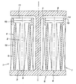
- This assembly comprises two coils, for example each with two outputs for the ignition of a twin-cylinder four-cylinder engine two to two motor vehicles.
- Each of the coils has a known core magnetic 2, a primary winding 3, a secondary winding 4 and a secondary winding 5.
- the two coils 1 are arranged symmetrically at inside an H-shaped magnetic circuit 6.
- Circuit 6 is composed of a stack of identical magnetic sheets arranged in the plane of the figure, and each comprising a barrel 7 and two pairs of branches 8.
- the branches 8 project from the bole 7 perpendicular to each of its ends, thus delimiting two parallelepipedic housings for the two coils.
- Each magnetic core 2 comprises a cylinder 9 based on circular, flared at one end to form a flare 10 disc-shaped.
- Magnetic core 2 including cylinder 9 and flare 10, is made of compressed iron powder. Because of the flare, compression is preferably applied transversely with a joint plane passing through the axis of the core. Compression is followed by deburring.
- the primary winding 3 is wound directly on the part cylindrical 9 of the magnetic core 2, without interposition of a coil primary.
- a permanent magnet 11 of the same shape and dimensions as the disc 10 is placed on the latter.
- the poles of the magnet 11 are axially directed.
- the assembly constituted by the magnetic core 2, the magnet permanent 11 and the secondary winding 3 is arranged inside a secondary coil 4.
- the latter is formed of a cylindrical tube plastic 12 in which is engaged the cylinder 9 and winding 3.
- This tube is flared at one of its ends to delimit a housing 13 receiving the flare 10 of the core magnetic and permanent magnet 11.
- the secondary winding 5 is wound on the tubular part 12 of the secondary coil 4, so as to form a coil complete ignition 1.
- the coils 1 and the magnetic circuit 6 are arranged in a plastic housing not shown, in which have been overmolded in a known manner the low power connections voltage and high voltage output. Output connections can moreover understand the bundle of cables connecting to the spark plugs engine ignition.
- the coils 1 are arranged relative to the circuit magnetic 6 so that each end is not flared magnetic cores 2 are substantially in contact with a branches 8 of a pair of branches.
- An air gap 14 is provided between the other branch 8 of the pair of branches and the permanent magnet 11 respective.
- Epoxy resin is then poured into the housing to immobilize and electrically isolate the various constituents of all.
- the invention makes it possible to produce very compact coils and high performance.
- the assembly which has just been described comprises two coils. A higher number, for example three, could be expected.
Landscapes
- Engineering & Computer Science (AREA)
- Power Engineering (AREA)
- Ignition Installations For Internal Combustion Engines (AREA)
Abstract
Description
- le noyau magnétique possède une section sensiblement circulaire et a au moins une de ses extrémités évasée ;
- le noyau magnétique est réalisé en poudre de fer comprimée ;
- l'enroulement primaire est directement bobiné sur le noyau magnétique ; et
- un aimant en forme de disque est disposé entre l'extrémité évasée du noyau magnétique et le circuit magnétique de retour de flux.
Claims (3)
- Bobine d'allumage pour moteur à combustion interne, comprenant un noyau magnétique (2), un enroulement primaire (3), un enroulement secondaire (5) et un circuit magnétique (6) de retour de flux, caractérisée par le fait que :le noyau magnétique (2) possède une section sensiblement circulaire et a au moins une de ses extrémités évasée (10) ;le noyau magnétique (2) est réalisé en poudre de fer comprimée ;l'enroulement primaire (3) est directement bobiné sur le noyau magnétique (2) ; etun aimant (11) en forme de disque est disposé entre l'extrémité évasée du noyau magnétique (2) et le circuit magnétique (6) de retour de flux.
- Ensemble d'allumage pour moteur à combustion interne, caractérisé par le fait qu'il comprend au moins une bobine d'allumage (1) selon la revendication 1.
- Ensemble d'allumage selon la revendication 1, dans lequel les bobines d'allumage (1) sont disposées symétriquement par rapport à un axe, le circuit magnétique (6) de retour de flux comprenant un fût (7) centré sur ledit axe et une pluralité de paires de branches (8), chaque paire de branches correspondant à une bobine d'allumage, et étant issue du fût (7) sensiblement perpendiculairement à ses extrémités respectives.
Applications Claiming Priority (2)
| Application Number | Priority Date | Filing Date | Title |
|---|---|---|---|
| FR9912751A FR2799880B1 (fr) | 1999-10-13 | 1999-10-13 | Bobine d'allumage a noyau magnetique en poudre de fer |
| FR9912751 | 1999-10-13 |
Publications (1)
| Publication Number | Publication Date |
|---|---|
| EP1093134A1 true EP1093134A1 (fr) | 2001-04-18 |
Family
ID=9550872
Family Applications (1)
| Application Number | Title | Priority Date | Filing Date |
|---|---|---|---|
| EP00402842A Withdrawn EP1093134A1 (fr) | 1999-10-13 | 2000-10-13 | Bobine d'allumage à noyau magnétique en poudre de fer |
Country Status (2)
| Country | Link |
|---|---|
| EP (1) | EP1093134A1 (fr) |
| FR (1) | FR2799880B1 (fr) |
Citations (5)
| Publication number | Priority date | Publication date | Assignee | Title |
|---|---|---|---|---|
| EP0297487A1 (fr) * | 1987-06-30 | 1989-01-04 | TDK Corporation | Transformateur |
| EP0352453A1 (fr) * | 1988-07-28 | 1990-01-31 | Nippondenso Co., Ltd. | Bobine d'allumage |
| FR2646551A1 (fr) * | 1989-04-28 | 1990-11-02 | Marchal Equip Auto | Connexions electriques du circuit secondaire d'une bobine d'allumage, en particulier pour moteur a combustion interne de vehicule automobile |
| EP0431322A1 (fr) * | 1989-11-10 | 1991-06-12 | Nippondenso Co., Ltd. | Bobine d'allumage |
| WO1995030992A1 (fr) * | 1994-05-10 | 1995-11-16 | Sagem Allumage | Bobine d'allumage destinee a etre montee sur une bougie pour l'alimentation electrique individuelle de cette bougie |
-
1999
- 1999-10-13 FR FR9912751A patent/FR2799880B1/fr not_active Expired - Fee Related
-
2000
- 2000-10-13 EP EP00402842A patent/EP1093134A1/fr not_active Withdrawn
Patent Citations (5)
| Publication number | Priority date | Publication date | Assignee | Title |
|---|---|---|---|---|
| EP0297487A1 (fr) * | 1987-06-30 | 1989-01-04 | TDK Corporation | Transformateur |
| EP0352453A1 (fr) * | 1988-07-28 | 1990-01-31 | Nippondenso Co., Ltd. | Bobine d'allumage |
| FR2646551A1 (fr) * | 1989-04-28 | 1990-11-02 | Marchal Equip Auto | Connexions electriques du circuit secondaire d'une bobine d'allumage, en particulier pour moteur a combustion interne de vehicule automobile |
| EP0431322A1 (fr) * | 1989-11-10 | 1991-06-12 | Nippondenso Co., Ltd. | Bobine d'allumage |
| WO1995030992A1 (fr) * | 1994-05-10 | 1995-11-16 | Sagem Allumage | Bobine d'allumage destinee a etre montee sur une bougie pour l'alimentation electrique individuelle de cette bougie |
Also Published As
| Publication number | Publication date |
|---|---|
| FR2799880B1 (fr) | 2002-01-04 |
| FR2799880A1 (fr) | 2001-04-20 |
Similar Documents
| Publication | Publication Date | Title |
|---|---|---|
| FR2857170A1 (fr) | Machine electrique tournante avec boitier de connection fixe sur son extremite axiale | |
| FR2812139A1 (fr) | Stator pour moteur de demarreur | |
| FR2851687A1 (fr) | Dispositif de stockage et de transformation d'energie | |
| EP0395512B1 (fr) | Bobine d'allumage, en particulier pour moteur à combustion interne de véhicule automobile, et moyens de maintien de l'ensemble primaire dans le secondaire | |
| EP0395511B1 (fr) | Dispositif de fixation d'une bobine d'allumage, en particulier pour moteur à combustion interne de véhicule automobile | |
| CA2835787C (fr) | Turbine generatrice de courant electrique | |
| CA2579152A1 (fr) | Enroulement depourvu de bobine et son procede de fabrication | |
| FR2629521A1 (fr) | ||
| EP1093134A1 (fr) | Bobine d'allumage à noyau magnétique en poudre de fer | |
| FR3051083A1 (fr) | Composant magnetique pour capteur a effet hall, ensemble electrique et compresseur de suralimentation electrique comprenant un tel composant magnetique | |
| EP3223393B1 (fr) | Machine electrique tournante ayant un ratio de dimensions minimisant les ondulations de couple | |
| EP0463895A1 (fr) | Moteur électrique de traction à courant continu pour véhicule automobile | |
| FR2462806A1 (fr) | Induit pour machine electrique tournante | |
| FR2785335A1 (fr) | Dispositif d'allumage pour moteur a combustion interne | |
| EP0340083A1 (fr) | Bobine d'allumage pour l'allumage des moteurs à combustion interne de véhicules automobiles, et son procédé de fabrication | |
| EP0072266B1 (fr) | Procédé d'obtention d'une bobine à circuit magnétique fermé et à aimant permanent pour l'allumage de moteurs à combustion | |
| FR2695267A1 (fr) | Stator de machine tournante électrique à aimants permanents, notamment pour démarreur. | |
| WO2021099533A1 (fr) | Machine électrique tournante avec blocage axial du stator | |
| FR2818001A1 (fr) | Bobine d'allumage a entrefer optimise | |
| EP1758219B1 (fr) | Bougie d'allumage pour un moteur à combustion interne | |
| EP0418137B1 (fr) | Bobine d'allumage, en particulier pour moteur à combustion interne de véhicule automobile | |
| EP0095964A1 (fr) | Collier d'accouplement réalisé par emboutissage et pliage d'un flan | |
| FR2521766A1 (fr) | Transformateur tournant | |
| FR2538182A1 (fr) | Servomoteur a courant continu du type a collecteur a aimants permanents | |
| FR2821710A1 (fr) | Circuit magnetique pour haut-parleur electrodynamique |
Legal Events
| Date | Code | Title | Description |
|---|---|---|---|
| PUAI | Public reference made under article 153(3) epc to a published international application that has entered the european phase |
Free format text: ORIGINAL CODE: 0009012 |
|
| AK | Designated contracting states |
Kind code of ref document: A1 Designated state(s): DE ES GB IT PT Kind code of ref document: A1 Designated state(s): AT BE CH CY DE LI |
|
| AX | Request for extension of the european patent |
Free format text: AL;LT;LV;MK;RO;SI |
|
| 17P | Request for examination filed |
Effective date: 20010323 |
|
| AKX | Designation fees paid | ||
| RBV | Designated contracting states (corrected) |
Designated state(s): AT BE CH CY DE LI |
|
| REG | Reference to a national code |
Ref country code: DE Ref legal event code: 8566 |
|
| RBV | Designated contracting states (corrected) |
Designated state(s): DE ES GB IT PT |
|
| RBV | Designated contracting states (corrected) |
Designated state(s): DE ES GB IT PT |
|
| RAP1 | Party data changed (applicant data changed or rights of an application transferred) |
Owner name: SAGEM S.A. |
|
| STAA | Information on the status of an ep patent application or granted ep patent |
Free format text: STATUS: THE APPLICATION IS DEEMED TO BE WITHDRAWN |
|
| 18D | Application deemed to be withdrawn |
Effective date: 20030503 |