EP1093257A1 - Méthode et appareil pour la restauration distribuée rapide d'un réseau de transmission - Google Patents
Méthode et appareil pour la restauration distribuée rapide d'un réseau de transmission Download PDFInfo
- Publication number
- EP1093257A1 EP1093257A1 EP00122060A EP00122060A EP1093257A1 EP 1093257 A1 EP1093257 A1 EP 1093257A1 EP 00122060 A EP00122060 A EP 00122060A EP 00122060 A EP00122060 A EP 00122060A EP 1093257 A1 EP1093257 A1 EP 1093257A1
- Authority
- EP
- European Patent Office
- Prior art keywords
- node
- nodes
- restoration
- message
- probe
- Prior art date
- Legal status (The legal status is an assumption and is not a legal conclusion. Google has not performed a legal analysis and makes no representation as to the accuracy of the status listed.)
- Withdrawn
Links
- 230000006854 communication Effects 0.000 title claims abstract description 75
- 238000004891 communication Methods 0.000 title claims abstract description 75
- 238000000034 method Methods 0.000 title claims abstract description 39
- 239000000523 sample Substances 0.000 claims abstract description 210
- 230000002457 bidirectional effect Effects 0.000 claims description 49
- 230000000694 effects Effects 0.000 claims description 24
- 238000001514 detection method Methods 0.000 claims description 5
- 108700042768 University of Wisconsin-lactobionate solution Proteins 0.000 description 16
- 238000010586 diagram Methods 0.000 description 14
- 238000013459 approach Methods 0.000 description 11
- 230000004044 response Effects 0.000 description 10
- 230000008569 process Effects 0.000 description 6
- 238000011084 recovery Methods 0.000 description 6
- 230000009471 action Effects 0.000 description 5
- 238000012790 confirmation Methods 0.000 description 5
- 238000010276 construction Methods 0.000 description 5
- RGNPBRKPHBKNKX-UHFFFAOYSA-N hexaflumuron Chemical compound C1=C(Cl)C(OC(F)(F)C(F)F)=C(Cl)C=C1NC(=O)NC(=O)C1=C(F)C=CC=C1F RGNPBRKPHBKNKX-UHFFFAOYSA-N 0.000 description 5
- 238000010606 normalization Methods 0.000 description 4
- 239000000835 fiber Substances 0.000 description 3
- 230000005540 biological transmission Effects 0.000 description 2
- 230000008439 repair process Effects 0.000 description 2
- 206010012411 Derailment Diseases 0.000 description 1
- 241000283984 Rodentia Species 0.000 description 1
- 230000004913 activation Effects 0.000 description 1
- 230000009286 beneficial effect Effects 0.000 description 1
- 230000007175 bidirectional communication Effects 0.000 description 1
- 238000004364 calculation method Methods 0.000 description 1
- 230000008859 change Effects 0.000 description 1
- 239000003814 drug Substances 0.000 description 1
- 238000005516 engineering process Methods 0.000 description 1
- 239000004744 fabric Substances 0.000 description 1
- 239000000976 ink Substances 0.000 description 1
- 238000012423 maintenance Methods 0.000 description 1
- 230000000737 periodic effect Effects 0.000 description 1
- 238000012545 processing Methods 0.000 description 1
- 238000010200 validation analysis Methods 0.000 description 1
Images


Classifications
-
- H—ELECTRICITY
- H04—ELECTRIC COMMUNICATION TECHNIQUE
- H04L—TRANSMISSION OF DIGITAL INFORMATION, e.g. TELEGRAPHIC COMMUNICATION
- H04L45/00—Routing or path finding of packets in data switching networks
Definitions
- each cable or fiber carries several thousand voice or data circuits.
- Such large network capacity provides advantages in terms of lower costs and greater payload flexibility.
- Fiber optic networks enjoy such advantages and other additional advantages, such as improved transmission quality.
- Networks have been known to suffer damage from backhoes at construction sites, power augers, lightning, rodents, fires, train derailments, bullets, vandalism, car crashes, ship anchors, trawler nets, and diverse other mishaps.
- interruptions in network operations be restored as quickly as possible in the event of a failure.
- APS automatic protection switching
- link is intended to indicate any communication path intermediate two adjacent nodes, or communication units, in a communication network.
- Adjacent nodes are communication units, such as cross connect systems, that are connected by a span. There can be more than one link in a span; a span is the set of all links in parallel between two adjacent nodes.
- Self-healing rings vary in the details of their implementation, but they can be conceptualized as an extension of either a 1:1 (100% redundancy) or a 1:N (greater than 100% redundancy) APS system. APS and SHR systems can effect recovery in 50 to 150 milliseconds. Such rapid recovery is very good, but the cost of such systems is prohibitively high except for the most critical of networks, such as for certain banking, medical, or stock market systems.
- a mesh network is a network in which each node may be connected to all other nodes in the network via links to adjacent nodes.
- intelligent internetworking devices such as nodal multiplexers in a T-carrier network, transmissions may be routed over an alternative path should the primary (direct) path between two sites be interrupted. Such interruption may be occasioned by congestion, or by a physical or electrical failure.
- Distributive restoration in a mesh network is another approach that has been discussed in attempting to accommodate restoration of a network.
- This distributed approach recognizes that digital cross-connect switches employed at nodes in a mesh network are computers, and they collectively represent considerable processing power embedded in a fabric of multiple communication links.
- every node (digital cross-connect switch) will perform to effect restoration as required in an apparently isolated manner, with no network-wide knowledge of the system.
- the independently deduced cross-connection decisions of each node will, in the aggregate, collectively constitute effective multipath rerouting plans.
- Most of the distributive restoration systems are less costly than an APS or an SHR system. However, the trade-off is that recovery time is not nearly as fast with the duplicative recovery systems. This stands to reason since there is no dedicated link to which traffic can be routed with very little delay.
- Most distributive restoration systems depend upon a flooding of the network with messages once an interruption is detected. The flooding messages explore all routes then viable in the network.
- the route (a series of spans denoted by a concatenation of nodes that establishes a way through the network) is chosen according to some predetermined route-choosing criteria. Such criteria may include the first (shortest) path identified, the greatest-capacity path, the inclusion of specified nodes within the path, the greatest path length efficiency, the fastest path, or other parameters.
- Grover W.D. Grover, "Distributed Restoration of the Transport Network", IEEE Network Management Into the 21 st Century, Chapter 11, February 1994 proposes distributed preplanning for restoration using a digital restoration algorithm.
- a self-healing network protocol is executed for each possible span failure in the network. This is accomplished by a full execution of the self-healing network protocol, but without actually making any cross-connections to effect rerouting. Instead, each node is to record the cross-connections it would have made according to the self-healing network protocol, and save those cross-connections in a table.
- each node will have stored in a table the instructions for that node's portion of the response to the self-healing network protocol for each and every respective span of the network.
- the network promulgates an alerting message and any alerted node having non-null actions in its respective table makes the internal cross-connections between spare ports that are listed in its table.
- Grover's proposed distributed preplanning involves storing in a table at each node each and every connection that node must participate in for each and every failure case. Such a table takes a significant amount of computing to amass, and a significant amount of time to complete. Grover himself acknowledges that there is a window of vulnerability on the order of seventeen minutes for a 100-span network. According to Grover, alerting can be accomplished either by an activation loop established through all digital cross-connect system (DCS) nodes, or by disseminating the alert through simple flooding.
- DCS digital cross-connect system
- Such a system should have a relatively simple and efficient approach to identifying restoration paths through the network, alerting appropriate network locations of the need for their participation in restoration on a timely basis, and automatically updating the restoration information periodically in a self-learning mode of operation.
- the invention is a method and apparatus for distributed managing of restoration paths within a communication network.
- the network includes a plurality of nodes connected by a plurality of internodal links, selected links of the plurality of internodal links being assigned links, other links being unassigned links.
- the preferred embodiment of the method of the present invention comprises the steps of: (a) establishing for selected nodes of the plurality of nodes a spare link catalog identifying each extant unassigned link connecting each selected node with an adjacent node; (b) operating each selected node as a probe originating node to send a probe message to each adjacent node over at least one unassigned link, preferably over one unassigned link; (c) evaluating the probe message at each adjacent node according to predetermined message handling criteria; (d) at each adjacent node, forwarding the probe message as a forwarded probe message to subsequent nodes adjacent to each adjacent node, or discarding the probe message, such forwarding or discarding being determined by the evaluating; (e) appending message content to the forwarded probe message indicating the node-to-node path sequence traversed by the probe message proceeding through the network; (f) evaluating the forwarded probe message at each subsequent node according to the predetermined message handling criterion; (g) repeating steps (d) through (f
- the method of the present invention may comprise the further steps of: (j) on detection of a link failure intermediate a first node and a second node, designating one of the first and second nodes as a sender node, and the other node as a receiver node; (k) operating the sender node to choose a selected restoration route from its restoration path register according to predetermined route selection criteria; (l) building a connection message at the sender node identifying the selected restoration route; (m) conveying the connection message to the receiver node; (n) establishing a bidirectional connection in each node intermediate the sender node and the receiver node in the selected restoration path; and (o) cooperatively orienting the sender node and the receiver node to effect communications via the selected restoration route.
- the apparatus of the present invention is a communication network system having a distributed restoration capability, the system comprising: a plurality of communication nodes for generating and handling messages, at least some of the nodes including a data store; a plurality of internodal communication links connecting the plurality of nodes; a spare link catalog distributively stored in at least some of the data stores and connected with the plurality of internodal links.
- the spare link catalog identifies each extant unassigned link connecting first selected nodes of the plurality of nodes with each node adjacent to each first selected node.
- the apparatus further comprises a restoration path register distributively stored in at least some of the data stores and connected with the plurality of internodal links.
- the restoration path register identifies alternate paths assignable from second selected nodes of the plurality of nodes to each node adjacent to each second selected node.
- the restoration path register includes node sequence information relating paths traversed by full-circuit probe messages sent by probe originating nodes of the plurality of nodes.
- Full-circuit probe messages are those probe messages which have been dispatched by a respective probe originating node, traversed more than one node other than the respective probe originating mode, and returned to the respective probe originating node.
- the system responds to a disruption of communications on one of the internodal communication links intermediate a first node and a second node of the plurality of nodes by operating one node of the first and second node to choose a selected restoration route from the restoration path register according to predetermined route selection criteria.
- the one node communicates the selected restoration route to the other node, and the one node and the other node orient to cooperatively effect communications via the selected restoration route.
- an object of the present invention to provide a method and apparatus for distributed managing of restoration paths within a communication network that are robust and reliable.
- a further object of the present invention is to provide a method and apparatus for distributed managing of restoration paths within a communication network which are simple and efficient in their approach to identifying restoration paths through the network.
- Yet a further object of the present invention is to provide a method and apparatus for distributed managing of restoration paths within a communication network which are simple and efficient in their approach to alerting appropriate network locations of the need for their participation in restoration on a timely basis.
- a further object of the present invention is to provide a method and apparatus for distributed managing of restoration paths within a communication network which are simple, efficient and fast in establishing restoration paths through the network.
- Still a further object of the present invention is to provide a method and apparatus for distributed managing of restoration paths within a communication network which are simple and efficient in their approach to automatically updating restoration information periodically in a self-learning mode of operation.
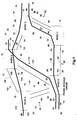
- Fig. 1 is a schematic diagram of a portion of a simplified network appropriate for employment of the present invention.
- a network 10 has a Node A 12, a Node B 14, a Node C 16, a Node D 18, and a Node E 20.
- the preferred embodiments of the apparatus and method of the present invention contemplate employment of the invention with a SONET/SDH system having inter-cross-connect links at an OC-48 level. For this reason, a bidirectional circuit is assumed throughout the description of the invention in this specification. It is stressed, however, that such an OC-48 system is referred to here for the purposes of illustration only, and that the method and apparatus of the present invention are employable with other network configurations with equally beneficial results.
- any spare link within the same span (a span is the set of all links in parallel between two adjacent nodes) will also fail later. It is for this reason that the present invention selects a restoration path using spare links which are not within the same span as the failed link.
- a spare link is a fully equipped link that is operational but is not in service, and can be accessed by the present invention for use in restoration operations. Such an approach to selecting restoration paths is valid in real world operations because an automatic protection switching (APS) system can be deployed if protection within the same span as the failed link is desired.
- APS automatic protection switching
- Node A 12 effects connection with network 10 through ports 22, 24, 26, 27, 28, 30, 31;
- Node B 14 effects connection with network 10 through ports 32, 34, 36, 38, 39, 40, 42;
- Node C 16 effects connection with network 10 through ports 44, 46, 48, 49, 50;
- Node D 18 effects connection with network 10 through ports 52, 54, 56, 58, 60, 62, 64, 66;
- Node E 20 effects connection with network 10 through ports 68, 70, 72, 74, 76.
- a span 70 intermediate Node A 12 and Node B 14 includes a working link 72 (indicated as a heavy line, as are all working links in Fig. 1) and a spare link 74 (indicated as a non-heavy line, as are all spare links in Fig. 1).
- Working link 72 is connected with Node A 12 via port 28, and is connected with Node B 14 via port 32.
- Spare link 74 is connected with Node A 12 via port 27, and is connected with Node B 14 via port 34.
- Node A 12 is connected with a working link 25 via a port 30 for connection with other components not shown in Fig. 1. Such other components may be other nodes in network 10, terminating or interface nodes establishing interfaces between network 10 and another network or a telephone central office, or another communication entity.
- Node B 14 is connected with working links 76, 78 for connection with other components not shown in Fig. 1. Connection between working link 76 and Node B 14 is effected via a port 42; connection between working link 78 and Node B 14 is effected via a port 40. A bidirectional connection 80 connects ports 32, 42 to effect communications between working links 72, 76.
- bidirectional connection 80 and other bidirectional connections to be described below in connection with Fig. 1, are preferably established using a head-end-bridge and a switch employed together.
- the construction of a head-end-bridge provides a unidirectional connection having a single input and a plurality of outputs.
- bidirectional connection 80 may effect communications in one direction using a head-end-bridge with a single input connected with port 32, and with one of a plurality of outputs connected with port 42 (the remaining outputs of the plurality of outputs are not shown in Fig. 1).
- a cross-point switch which changes an input from a first cross-point to another cross-point.
- Such a switch would preferably be employed in establishing bidirectional connection 80, for example, to switch inputs received at port 42 from a first cross-point (not shown in Fig. 1) to a second cross-point which is connected with bidirecional connection 80.
- Such employment of head-end-bridge and cross-point switches to establish a bidirectional connection is a particular, preferred, construction. Other constructions may also be employed to establish bidirectional connections without straying beyond the intended scope of the present invention.
- Node B 14 is also connected with Node C 16 via a span 82.
- Span 82 includes a working link 84 and spare links 86, 87.
- Working link 84 connects with Node B 14 via port 36, and connects with Node C 16 via port 50.
- Spare link 86 is connected with Node B 14 via port 38, and is connected with Node C 16 via port 48.
- Spare link 87 is connected with Node B 14 via port 39, and is connected with Node C 16 via port 49.
- a bidirectional connection 88 is provided in Node B 14 to connect working link 78 with working link 84 via ports 36, 40.
- a span 90 intermediate Node C 16 and Node D 18 includes a working link 92 and a spare link 94.
- Working link 92 is connected with Node C 16 via port 44, and is connected with Node D 18 via port 58.
- Spare link 94 is connected with Node C 16 via port 46, and is connected with Node D 18 via port 56.
- a bidirectional connection 89 is provided in Node C 16 to connect working links 84, 92 via ports 44, 50.
- a span 96 intermediate Node D 18 and Node E 20 includes spare links 98, 100.
- Spare link 98 is connected with Node D 18 via port 64, and is connected with Node E 20 via port 72.
- Spare link 100 is connected with Node D 18 via port 66, and is connected with Node E 20 via port 70.
- Working links 93, 95 are provided to Node D 18 for connection with other components not shown in Fig. 1.
- Working link 93 is connected with Node D 18 via port 52; working link 95 is connected with Node D 18 via port 54.
- a bidirectional connection 99 is provided in Node D 18 between ports 52, 60 for establishing communications between working link 93 and a working link 112.
- a bidirectional connection 101 is provided in Node D 18 between ports 54, 58 for establishing communications between working links 92, 95.
- a span 102 intermediate Node E 20 and Node A 12 includes a working link 104 and a spare link 106.
- Working link 104 is connected with Node E 20 via port 74, and is connected with Node A 12 via port 22.
- Spare link 106 is connected with Node E 20 via port 76 and is connected with Node A 12 via port 31.
- Node E 20 is also connected with a working link 108 via port 68.
- Working link 108 is connected with other components not shown in Fig. 1. Such other components may be other nodes in network 10, terminating or interface nodes establishing interfaces between network 10 and another network or a telephone central office, or another communication entity.
- a bidirectional connection 103 is provided in Node E 20 between ports 68, 74 for establishing communications intermediate working links 104, 108.
- a span 110 intermediate Node A 12 and Node D 18 includes a working link 112 and a spare link 114.
- Working link 112 is connected with Node A 12 via port 26, and is connected with Node D 18 via port 60.
- Spare link 114 is connected with Node A 12 via port 24, and is connected with Node D 18 via port 62.
- a bidirectional connection 109 is provided in Node A 12 between ports 22, 28 for connecting working links 72, 104.
- a bidirectional connection 111 is also provided in Node A 12 between ports 26, 30 for connecting working links 25, 112.
- a spare link data base (also referred to as a spare link catalog) is generated in order to maintain an up-to-date inventory of spare links available for restoration involvement.
- Each node 12, 14, 16, 18, 20 is assigned a unique identification.
- Each spare link can send a continuous "idle" message to its adjacent node, or alternatively, an "idle” message may be transmitted periodically.
- Idle messages preferably should include such information as the node identifications for its originating node, the port connecting the spare link with the receiving node, and the state of the port.
- the spare link database information generated from the various idle messages is preferably stored at each respective node for those spare links relating to that node.
- information regarding spare link 74 would be stored at nodes 12, 14; information relating to spare link 86 would be stored at nodes 14, 16.
- information relating to spare link 94 would be stored at nodes 16, 18; information relating to spare links 98, 100 would be stored at nodes 18, 20, and information relating to spare link 114 would be stored at nodes 12, 18.
- Information relating to spare link 106 would be stored at nodes 12, 20.
- Table 1 below is an example of a spare link database for Node D 18 in Fig. 1.
- ADJACENT NODE ID NODE CONNECTED TO (LINK ID) LOCAL SPARE FAR-END SPARE AVAIL FOR RESTORING PORT ID STATE PORT ID STATE 12 114 62 24 YES 16 94 56 46 YES 20 100 66 70 NO 20 98 64 72 NO Identification numbers refer to reference numerals in Fig. 1.
- the availability of spare links for participation in restoration configurations is automatic and continually up-to-date.
- the network is, thus, a self-learning network in keeping track of its restoration-related resources.
- a restoration route database is generated for each node 12, 14, 16, 18, 20 and information relating to restoration routing is preferably stored at each respective node 12, 14, 16, 18, 20 relating to that node.
- a route-searching process is undertaken to create a restoration route database for each node 12, 14, 16, 18, 20.
- the route-searching process may be undertaken at the request of a network manager, or it may be periodically- or event-driven, or a combination of impetuses.
- a node 12, 14, 16, 18, 20 performs a route-searching by sending a probe message on its spare links to each adjacent node. Preferably only one probe message is sent per span. If there are multiple spare links available in a span, only one spare link is chosen to carry the probe message.
- the probe message includes the source node's identification and a hop count ⁇ a definition of the maximum number of nodes allowed to be included in a restoration path. Hop count is preferably user-settable.
- an adjacent node When an adjacent node receives a probe message from a source node, it follows specified rules to evaluate the probe message received, and deals with the probe message according to those rules.
- An example of such predetermined rules is:
- the node list compiled as each successive forwarding node appends information according to Rule (4)(a) above provides the route list for each respective restoration route identified by each returning probe message.
- the number of spare links available to a respective restoration route to protect a link will be the smallest number of the available spare links listed among the appended data provided by forwarding nodes.
- an error report is preferably generated for alerting the network managing authority that no restoration route is available for the affected span.
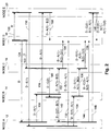
- Fig. 2 is a schematic message ladder diagram illustrating an example of probe message flow and route-searching originating from one node within the network illustrated in Fig. 1, according to the preferred embodiment of the present invention.
- the origin of a probe message from Node D 18 (Fig. 1) and route-searching by that probe message through network 10 of Fig. 1 is shown.
- Node D 18 originates three probe messages 120, 122, 124.
- Each of the probe messages 120, 122, 124 indicates that its origin is "D", i. e., Node D 18.
- Probe message 120 is sent to Node E 20 on either of spare links 98, 100 (Fig. 1).
- Fig. 2 For purposes of this example illustrated in Fig. 2, it is assumed that there are no occasions for discarding a probe message under the rules observed by the nodes in evaluating probe messages, such as the exemplary rules enumerated above. Further, in order to simplify the explanation of the exemplary probe messages illustrated in Fig. 2, it is assumed that all links are in service and in standby mode (i.e., the exemplary information contained in Table 2 above does not apply to the following explanation of Fig. 2)
- Node E 20 forwards probe message 120 as a forwarded probe message 130 to Node A 12 on spare link 106 (Fig. 1).
- the information appended to forwarded probe message 130 indicates that probe message 130 originated with Node D 18 and traveled via Node E 20, and that span 102 from Node E 20 to Node A 12 has one spare link: "D ⁇ E(1)".
- Node A 12 then forwards forwarded probe message 130 to Node D 18 as a forwarded probe message 132 via spare link 114.
- forwarded probe message 132 is a returned probe message which originated at Node D 18, and contains a complete restoration route in its appended information.
- the restoration route proceeds from Node D 18 via one of spare links 98, 100 to Node E 20, thence to Node A 12 via spare link 106 in span 102 (having one spare link available), and thence back to Node D 18 via spare link 114 in span 110 (having one spare link available).
- This information is contained in the message information of forwarded probe message 132: "D ⁇ E(1) ⁇ A(1)".
- Node A 12 also forwards forwarded probe message 130 to Node B 14 as a forwarded probe message 134.
- the information appended to forwarded probe message 134 indicates that forwarded probe message 134 originated with Node D 18 and traveled via Node E 20 and via Node A 12.
- the appended information also indicates that span 102 from Node E 20 and span 70 from Node A 12 each has one spare link: "D ⁇ E(1) ⁇ A(1)".
- Node B 14 then forwards forwarded probe message 134 to Node C 16 via either of spare links 86, 87 as a forwarded probe message 136.
- the information appended to forwarded probe message 136 indicates that forwarded probe message 136 originated with Node D 18 and traveled via Node E 20, via Node A 12 and via Node B 14.
- the appended information also indicates that each span 102, 70 from Node E 20 and from Node A 12 has one spare link, and that span 82 from Node B 14 has two spare links : "D ⁇ E(1) ⁇ A(1) ⁇ B(2)".
- forwarded probe message 138 is a returned probe message which originated at Node D 18, and contains a complete restoration route in its appended information.
- the restoration route proceeds from Node D 18 via one of spare links 98, 100 of span 96 and travels via Node E 20, via span 102, via Node A 12, via span 70, via Node B 14, via span 82, via Node C 16, and via span 90.
- the message information of forwarded probe message 138 also indicates that each span 102, 70, 90 from Node E 20, Node A 12, and Node C 16 has one spare link, and that span 82 from Node B 14 has two spare links: "D ⁇ E(1) ⁇ A(1) ⁇ B(2) ⁇ C(1)".
- Probe message 122 is sent from Node D 18 to Node C 16 via spare link 94 (Fig. 1).
- Node C 16 forwards probe message 122 to Node B 14 as a forwarded probe message 140 via either of spare links 86, 87.
- the information appended to forwarded probe message 140 indicates that forwarded probe message 140 originated with Node D 18 and traveled via Node C.
- the appended information also indicates that span 82 from Node C 16 has two spare links: "D ⁇ C(2)".
- Node B 14 then forwards forwarded probe message 140 to Node A 12 via spare link 74 as a forwarded probe message 142.
- the information appended to forwarded probe message 142 indicates that forwarded probe message 142 originated with Node D 18 and traveled via Node C 16 and via Node B 14.
- the appended information also indicates that span 82 from Node C 16 has two spare links, and span 70 from Node B 14 has one spare link: "D ⁇ C(2) ⁇ B(1)".
- forwarded probe message 144 is a returned probe message which originated at Node D 18, and contains a complete restoration route in its appended information.
- the restoration route proceeds from Node D 18 via spare link 94 of span 90 and travels via Node C 16, via span 82, via Node B 14, via span 70, via Node A 12, and via span 110.
- the message information of forwarded probe message 144 also indicates that span 82 from Node C 16 has two spare links, and each span 70, 110 from Node B 14 and from Node A has one spare link: "D ⁇ C(2) ⁇ B(1) ⁇ A(1)".
- Node A 12 also forwards forwarded probe message 142 to Node E 20 as a forwarded probe message 146.
- the information appended to forwarded probe message 146 indicates that forwarded probe message 146 originated with Node D 18 and traveled via Node C 16, via Node B 14, and via Node A 12.
- the appended information also indicates that span 82 from Node C 16 has two spare links, and each span 70, 102 from Node B 14 and from Node A 12 has one spare link: "D ⁇ C(2) ⁇ B(1) ⁇ A(1)".
- Node E 20 then forwards forwarded probe message 146 to Node D 18 via one of spare links 98, 100 as a forwarded probe message 148.
- forwarded probe message 148 is a returned probe message which originated at Node D 18, and contains a complete restoration route in its appended information.
- the restoration route proceeds from Node D 18 via spare link 94 of span 90 and travels via Node C 16, via span 82, via Node B 14, via span 70, via Node A 12, via span 102, via Node E 20 and via span 96.
- the message information of forwarded probe message 148 also indicates that each span 82, 96 from Node C 16 and from Node E 20 has two spare links, and each span 70, 110 from Node B 14 and from Node A 12 has one spare link: "D ⁇ C(2) ⁇ B(1) ⁇ A(1) ⁇ E(2)".
- Probe message 124 is sent from Node D 18 to Node A 12 via spare link 114 (Fig. 1). Node A 12 forwards probe message 124 to Node B 14 as a forwarded probe message 150 via spare link 74 of span 70.
- the information appended to forwarded probe message 150 indicates that forwarded probe message 150 originated with Node D 18 and traveled via Node A 12.
- the appended information also indicates that span 70 from Node A 12 has one spare link: "D ⁇ A(1)".
- Node B 14 then forwards forwarded probe message 150 to Node C 16 via either of spare links 86, 87 as a forwarded probe message 152.
- the information appended to forwarded probe message 152 indicates that forwarded probe message 152 originated with Node D 18 and traveled via Node A 12 and via Node B 14.
- the appended information also indicates that span 82 from Node B 14 has two spare links, and span 70 from Node A 12 has one spare link: "D ⁇ A (1) ⁇ B(2)".
- forwarded probe message 154 is a returned probe message which originated at Node D 18, and contains a complete restoration route in its appended information.
- the restoration route proceeds from Node D 18 via spare link 114 of span 110 and travels via Node A 12, via span 70, via Node B 14, via span 82, via Node C 16, and via span 90.
- the message information of forwarded probe message 154 also indicates that span 82 from Node B 14 has two spare links, and each span 70, 90 from Node A 12 and from Node C 16 has one spare link: "D ⁇ A(1) ⁇ B(2) ⁇ C(1)".
- Node A 12 also forwards probe message 124 to Node E 20 as a forwarded probe message 156 via spare link 106 of span 102.
- the information appended to forwarded probe message 156 indicates that forwarded probe message 156 originated with Node D 18 and traveled via Node A 12.
- the appended information also indicates that span 102 from Node A 12 has one spare link: "D ⁇ A(1)".
- forwarded probe message 158 is a returned probe message which originated at Node D 18, and contains a complete restoration route in its appended information.
- the restoration route proceeds from Node D 18 via spare link 114 of span 110 and travels via Node A 12, via span 102, via Node E 20, and via span 96.
- the message information of forwarded probe message 158 also indicates that span 96 from Node E 20 has two spare links, and span 102 from Node A 12 has one spare link: "D ⁇ A (1) ⁇ E(2)".
- Table 2 reflects the unidirectional restoration routes determined by the procedure discussed above in connection with Fig. 2.
- a bidirectional restoration route data base may also be created, once both directions of the restoration routes are verified.
- Table 3 illustrates such a bidirectional restoration route data base for Node D 18.
- the configuration of a network such as network 10 (Fig. 1) may likely change after a determination of restoration routes has been made and stored in a restoration route data base.
- Network configuration changes may be caused by such things as changing working connections, installing a new node in the network, maintenance actions, or other causes.
- the restoration route data be kept up-to-date at each node in a network in order that proper restoration operations may be effected at any time.
- the restoration route data base be configured to facilitate updating at least (1) periodically according to a timer, (2) when the network system is initialized, (3) when requested by the network manager, (4) when a connection is made, (5) when a local working/spare configuration is altered, and (6) after an automatic restoration has taken place.
- restoration routes may be distributed among nodes in a network in any pattern desired; it is not an absolute requirement that each node store its own restoration route information and spare link information.
- a network may be segmented into regions and restoration information may be stored at a regional center for those nodes in a respective network region.
- the preferred embodiment of the present invention contemplates storage of restoration information ⁇ including spare link information and restoration route information ⁇ at each respective node affected by the stored information.
- Fig. 3 is a schematic diagram of a portion of network 10 presented in Fig. 1, illustrating automatic restoration according to the present invention.
- network 10 is illustrated in somewhat simplified form. Only spare links 74, 86, 87, 98, 100, 106. 114 are illustrated. Only the existing network route connecting working link 93 with working link 25 via working link 112 intermediate Node A 12 and Node D 18, and via bidirectional connections 99, 111 is illustrated.
- working link 112 is failed, as indicated by a break 160. It is the usual case that a failed link exhibits signal failures in both directions between custodial nodes, the nodes adjacent to a span containing a failed link. In such situations, both custodial nodes detect the fault substantially simultaneously.
- the preferred embodiment of the present invention provides that detection of a fault will cause only one custodial node to initiate a restoration action.
- the restoration system responds to detection of a fault by designating one of the custodial nodes a Sender Node and the other of the custodial nodes a Receiver Node.
- the role designation i.e., Sender Node and Receiver Node
- Such an automatic operation may be effected, for example, by each node keeping track of its own node identification designation (ID) and adjacent nodes" Ids.
- the custodial nodes will necessarily be adjacent nodes.
- a simple operational rule may be employed, such as by way of example, when an adjacent node has an ID greater than a given node's own ID, then the adjacent node is designated as a Sender Node, and the given node making the comparison of ID's is designated as a Receiver Node.
- each custodial node associated with a fault can independently determine whether it is a Sender Node or a Receiver Node without communicating with any other nodes.
- Node D 18 is designated the Sender Node
- Node A 12 is designated the Receiver Node.
- each Intermediate Node in the selected restoration route intermediate the Sender Node and the Receiver Node will:
- the Receiver Node completes the automatic restoration action upon receiving the connection message by:
- spare links may be assigned on a first-come-first-served basis, according to a predetermined priority scheme, or according to some other criteria.
- Sender Node 18 upon detecting the fault caused by break 160, sends a connection message to Receiver Node 12 advising Receiver Node 12 of the identity of Sender Node 18, reciting the identity of Receiver Node 12, and specifying the node list of the chosen restoration route.
- the chosen restoration route is to be established via nodes 16, 14.
- the connection message from Sender Node 18 to Receiver Node 12 will also specify the port 26 to be rolled from by Receiver Node 12.
- Sender Node 18 sends the connection message to adjacent Intermediate Node 16 via the chosen spare link 94 (in this case, the only available spare link for span 90).
- Sender Node 18 also establishes a bidirectional connection 162 to connect traffic from its port 52 to port 56 to effect traffic routing to chosen spare link 94.
- Intermediate Node 16 selects a spare link connecting the next node of the selected restoration route, Intermediate Node 14.
- Intermediate Node 16 chooses spare link 86 for connection with Intermediate Node 14.
- the connection message is forwarded to Intermediate Node 14 via selected spare link 86.
- Intermediate Node 16 also establishes a bidirectional connection 164 to effect a bidirectional cross-connection between ports 46, 48, thereby connecting spare links 94, 86.
- Intermediate Node 14 selects a spare link connecting the next node of the selected restoration route, Receiver Node 12.
- Intermediate Node 14 chooses spare link 74, the only spare link available for connection with Receiver Node 12.
- the connection message is forwarded to Receiver Node 12 via selected spare link 74.
- Intermediate Node 14 also establishes a bidirectional connection 166 to effect a bidirectional cross-connection between ports 38, 34, thereby connecting spare links 74, 86.
- Receiver Node 12 receives the connection message and switches traffic from port 26 to port 27, the port on which the connection message was received. Receiver Node 12 also establishes a bidirectional connection 168 connecting ports 27, 30 in order to direct traffic received from working link 25 to port 27 and, thence, to the selected restoration route. Once traffic is received by Sender Node 18 from Receiver Node 12 via the restoration route through Intermediate Nodes 14, 16, the automatic restoration operation is completed.
- Fig. 4 is a schematic message ladder diagram illustrating messages effecting the automatic restoration represented in Fig. 3.
- Node D 18 is a custodial node with respect to break 160 (Fig. 3), and is designated the Sender Node 18.
- Sender Node 18 sends a connection message 170 to adjacent Intermediate Node 16 in the selected restoration route (Fig. 3) via spare link 94.
- Intermediate Node 16 forwards the connection message 170 as a forwarded connection message 172 to Intermediate Node 14 via spare link 86, and Intermediate Node16 performs other functions and operations such as establishing bidirectional connection 164, as described above in connection with Fig. 3.
- Intermediate Node 14 forwards forwarded connection message 172 as a forwarded connection message 174 to Receiver Node 12 via spare link 74, and Intermediate Node14 performs other functions and operations such as establishing bidirectional connection 166, as described above in connection with Fig. 3.
- Receiver Node 12 receives forwarded connection message 174 and effects connection via bidirectional connection 168 with working link 25.
- Communication is established from Receiver Node 12 to Sender Node 18 via spare link 74, via Intermediate Node 14, via spare link 86, via Intermediate Node 16, and via spare link 94, then the automatic restoration operation is completed.
- the preferred embodiment of the present invention effects a bidirectional restoration.
- a far end failure indication may be inserted in an outgoing message from the node detecting the far end failure. This event will trigger an automatic bidirectional restoration operation to establish bidirectional communications as described hereinbefore.
- Fig. 5 is a schematic diagram of a portion of the simplified network presented in Fig. 1, illustrating normalization of routing after link repair, according to the present invention.
- link 112 is repaired and any required wait-to-restore time imposed by the system operator has expired.
- Link 112 is ready for service.
- Sender Node 18 thereupon sends a return-to-normal command message via the repaired, original link 112.
- Receiver Node 12 verifies that link 112 is in a valid state for reversion to normal operations, and then switches traffic back to its original path via bidirectional connection 111 between ports 26, 30.
- Receiving Node 12 then sends a confirmation response message to Sender Node 18 via the original link 112.
- Sender Node 18 After Sender Node 18 receives the confirmation response message via link 112, Sender Node 18 switches traffic back to its original path along bidirectional connection 99 between ports 52, 60, drops bidirectional connection 162, and sends a disconnect message to Receiver Node 12 via the restoration path.
- the restoration path connections and bidirectional connections 164, 166, 168 in Intermediate Nodes 14, 16 and in Receiver Node 12 are discontinued upon receiving the disconnect message.
- Fig. 6 is a schematic message ladder diagram illustrating messages effecting the normalization of routing represented in Fig. 3.
- Node D 18 is a custodial node with respect to break 160 (Fig. 3), and is designated the Sender Node 18.
- Sender Node 18 sends a return-to-normal message 180 to Receiver Node 12 via original, restored, link 112.
- Receiver Node 12 verifies that link 112 is ready for service, and then sends a confirmation message 182 to Sender Node 18 via link 112. At this point, Receiver Node 12 also switches its traffic back to its original traffic path via bidirectional connection 111 to link 112.
- a restoration route data base of a path-based system would contain restoration routes from one path-terminating mode to another path-terminating node so that, in building restoration routes with probe messages, as taught herein, a probe message originating node will only select routes for storage as possible restoration routes those routes which are established by returning probe messages having reached the other path-terminating node.
- custodial nodes to the failed link need to identify the affected span to path termination nodes so that routes containing the failed span will not be selected for inclusion in a restoration route.
- Fig. 7 is a schematic flow diagram illustrating the preferred embodiment of the method of the present invention.
- spare links are identified by sending idle messages, preferably periodically as well as on the occurrence of particular events, and a spare link catalog is established and stored, preferably at each respective node in the network to which the spare links connect, as indicated by block 200.
- each node Periodically and on occurrence of predetermined events, each node, operating as a probe originating node, sends a probe message to each adjacent node in the network over an unassigned link, as indicated by block 202.
- Each adjacent node upon receiving a probe message, evaluates the probe message according to predetermined criteria, as indicated by query block 204 (and as described in greater detail hereinbefore). If the probe message does not meet the predetermined criteria, then the method proceeds according to "NO" response path 206, and the probe message is discarded, as indicated by block 208.
- the method proceeds according to "YES" response path 210, and the probe message is forwarded to each next adjacent node, as indicated by block 212.
- Message content indicating the path sequence traversed by the probe message proceeding through the network is appended to the forwarded probe message, as indicated by block 214.
- the method proceeds to query block 216 where the node receiving the forwarded probe message inquires whether the probe message received was originated by the node making the query. If the forwarded probe message was not originated by the then-evaluating node, then the method proceeds according to "NO" response path 218 to query block 204, and the forwarded probe message is again examined according to predetermined criteria. The method proceeds from query block 204 according to whether the forwarded probe message meets the predetermined criteria, as described before. If the forwarded probe message was originated by the node conducting the inquiry according to query block 216, then the forwarded probe message is a returned probe message and the method proceeds according to "YES" response path 220. In such case, a restoration route has been established, and restoration path information is stored, according to block 222. Thereafter, network operations are continued, according to block 224.
- the process continues via "NO" response path 228, and operations continue, as indicated by block 224.
- a link failure occurs, the process proceeds from query block 226 via "YES" response path 230, and one of the custodial nodes adjacent the span containing the failed link is designated as a Sender Node according to block 232; the other custodial node is designated as a Receiver Node.
- the Sender Node chooses a restoration path from the stored restoration path data stored pursuant to block 222, as indicated by block 234.
- the Sender Node then advises the Receiver Node of the restoration path chosen, communicating the notice via the chosen restoration path, as indicated by block 236.
- the present invention is used in a SONET/SDH environment.
- the invention can, of course be used with other communication environments .
- An example of using the invention with a SONET/SDH environment contemplates that the 94 unused D1 and D2 bytes or K1 and K2 bytes in a SONET OC-48 section, or line overhead can be used to transport the messages required for implementing the present invention.
- a cross-connect switch should have the capability to drop and insert messages.
- the idle message for determining spare links for inclusion in the spare link catalog is preferably transmitted continually at a rate provided by the network manager.
- All other messages associated with the present invention are preferably transmitted one time in at least three consecutive frames in a SONET/SDH system. Upon receipt, all messages are preferable integrated over three frames for validation purposes.
Landscapes
- Engineering & Computer Science (AREA)
- Computer Networks & Wireless Communication (AREA)
- Signal Processing (AREA)
- Data Exchanges In Wide-Area Networks (AREA)
Applications Claiming Priority (2)
| Application Number | Priority Date | Filing Date | Title |
|---|---|---|---|
| US416545 | 1999-10-12 | ||
| US09/416,545 US6549513B1 (en) | 1999-10-12 | 1999-10-12 | Method and apparatus for fast distributed restoration of a communication network |
Publications (1)
| Publication Number | Publication Date |
|---|---|
| EP1093257A1 true EP1093257A1 (fr) | 2001-04-18 |
Family
ID=23650386
Family Applications (1)
| Application Number | Title | Priority Date | Filing Date |
|---|---|---|---|
| EP00122060A Withdrawn EP1093257A1 (fr) | 1999-10-12 | 2000-10-11 | Méthode et appareil pour la restauration distribuée rapide d'un réseau de transmission |
Country Status (3)
| Country | Link |
|---|---|
| US (1) | US6549513B1 (fr) |
| EP (1) | EP1093257A1 (fr) |
| CA (1) | CA2317979A1 (fr) |
Cited By (1)
| Publication number | Priority date | Publication date | Assignee | Title |
|---|---|---|---|---|
| EP3654555A1 (fr) * | 2018-11-15 | 2020-05-20 | Nokia Solutions and Networks Oy | Commutateur de protection à réagencement polyvalent |
Families Citing this family (112)
| Publication number | Priority date | Publication date | Assignee | Title |
|---|---|---|---|---|
| US6535481B1 (en) * | 1999-08-20 | 2003-03-18 | Nortel Networks Limited | Network data routing protection cycles for automatic protection switching |
| US6836463B2 (en) * | 1999-10-15 | 2004-12-28 | Nokia Corporation | System for communicating labeled routing trees to establish preferred paths and source routes with local identifiers in wireless computer networks |
| US6970417B1 (en) * | 1999-12-28 | 2005-11-29 | At&T Corp. | Methods and systems for fast restoration in a mesh network of optical cross connects |
| US7002908B1 (en) * | 2000-02-28 | 2006-02-21 | Telefonaktiebolaget Lm Ericsson (Publ) | Interconnection link redundancy in a modular switch node |
| US7009980B1 (en) * | 2000-03-13 | 2006-03-07 | Lucent Technologies Inc. | Apparatus and method for automatic port identity discovery in hierarchical heterogenous systems |
| US6732175B1 (en) | 2000-04-13 | 2004-05-04 | Intel Corporation | Network apparatus for switching based on content of application data |
| US7177927B1 (en) * | 2000-08-22 | 2007-02-13 | At&T Corp. | Method for monitoring a network |
| JP2002164893A (ja) * | 2000-09-06 | 2002-06-07 | Toshiba Corp | 情報伝送ネットワークシステムの制御方法 |
| EP1346518B1 (fr) * | 2000-12-05 | 2010-07-07 | RIT Technologies Ltd. | Systeme d'identification automatique de l'emplacement physique de terminaux connectes a un reseau |
| US7051113B1 (en) * | 2001-06-01 | 2006-05-23 | Cisco Technology, Inc. | Method and apparatus for computing a primary path while allowing for computing an alternate path by using a blocked list |
| US7289429B2 (en) * | 2001-06-01 | 2007-10-30 | Fujitsu Network Communications, Inc. | System and method to perform non-service effecting bandwidth reservation using a reservation signaling protocol |
| US7652983B1 (en) * | 2001-06-25 | 2010-01-26 | At&T Intellectual Property Ii, L.P. | Method for restoration and normalization in a mesh network |
| US7725039B2 (en) * | 2001-07-18 | 2010-05-25 | Meriton Networks Us Inc. | Method and apparatus for automatic port interconnection discovery in an optical network |
| US7146524B2 (en) | 2001-08-03 | 2006-12-05 | Isilon Systems, Inc. | Systems and methods for providing a distributed file system incorporating a virtual hot spare |
| US7685126B2 (en) | 2001-08-03 | 2010-03-23 | Isilon Systems, Inc. | System and methods for providing a distributed file system utilizing metadata to track information about data stored throughout the system |
| US6766482B1 (en) | 2001-10-31 | 2004-07-20 | Extreme Networks | Ethernet automatic protection switching |
| US7139824B2 (en) * | 2001-11-28 | 2006-11-21 | International Business Machines Corporation | Method and system for isolating and simulating dropped packets in a computer network |
| CA2420842C (fr) * | 2002-03-06 | 2010-05-11 | Nippon Telegraph And Telephone Corporation | Noeud de niveau superieur, noeud de niveau inferieur, et methode de commande de noeud |
| US7480253B1 (en) * | 2002-05-30 | 2009-01-20 | Nortel Networks Limited | Ascertaining the availability of communications between devices |
| US7525907B2 (en) * | 2002-07-05 | 2009-04-28 | Nortel Networks Limited | Method, device and software for establishing protection paths on demand and revertive protection switching in a communications network |
| US20040062195A1 (en) * | 2002-09-30 | 2004-04-01 | Intel Corporation | Algorithm for dynamic provisioning of fail-over support in generalized multi-protocol label switching enabled networks |
| US7937421B2 (en) | 2002-11-14 | 2011-05-03 | Emc Corporation | Systems and methods for restriping files in a distributed file system |
| US20040131065A1 (en) * | 2003-01-08 | 2004-07-08 | Sandy Douglas L. | Distributed switch fabric network and method |
| US7646706B2 (en) * | 2003-03-31 | 2010-01-12 | Alcatel-Lucent Usa Inc. | Restoration time in mesh networks |
| US8296407B2 (en) * | 2003-03-31 | 2012-10-23 | Alcatel Lucent | Calculation, representation, and maintenance of sharing information in mesh networks |
| US8867333B2 (en) * | 2003-03-31 | 2014-10-21 | Alcatel Lucent | Restoration path calculation considering shared-risk link groups in mesh networks |
| US7545736B2 (en) * | 2003-03-31 | 2009-06-09 | Alcatel-Lucent Usa Inc. | Restoration path calculation in mesh networks |
| US7643408B2 (en) * | 2003-03-31 | 2010-01-05 | Alcatel-Lucent Usa Inc. | Restoration time in networks |
| US7689693B2 (en) * | 2003-03-31 | 2010-03-30 | Alcatel-Lucent Usa Inc. | Primary/restoration path calculation in mesh networks based on multiple-cost criteria |
| US7606237B2 (en) | 2003-03-31 | 2009-10-20 | Alcatel-Lucent Usa Inc. | Sharing restoration path bandwidth in mesh networks |
| US7451340B2 (en) * | 2003-03-31 | 2008-11-11 | Lucent Technologies Inc. | Connection set-up extension for restoration path establishment in mesh networks |
| US7269347B1 (en) | 2003-05-28 | 2007-09-11 | Ciena Corporation | Optical receiver decision threshold tuning apparatus and method |
| US8078756B2 (en) * | 2003-06-03 | 2011-12-13 | Cisco Technology, Inc. | Computing a path for an open ended uni-directional path protected switched ring |
| US7165192B1 (en) * | 2003-12-19 | 2007-01-16 | Sun Microsystems, Inc. | Fault isolation in large networks |
| US20050226212A1 (en) * | 2004-04-02 | 2005-10-13 | Dziong Zbigniew M | Loop avoidance for recovery paths in mesh networks |
| US7500013B2 (en) * | 2004-04-02 | 2009-03-03 | Alcatel-Lucent Usa Inc. | Calculation of link-detour paths in mesh networks |
| US8111612B2 (en) * | 2004-04-02 | 2012-02-07 | Alcatel Lucent | Link-based recovery with demand granularity in mesh networks |
| US8055711B2 (en) | 2004-10-29 | 2011-11-08 | Emc Corporation | Non-blocking commit protocol systems and methods |
| US8051425B2 (en) * | 2004-10-29 | 2011-11-01 | Emc Corporation | Distributed system with asynchronous execution systems and methods |
| US8238350B2 (en) * | 2004-10-29 | 2012-08-07 | Emc Corporation | Message batching with checkpoints systems and methods |
| US7586888B2 (en) * | 2005-02-17 | 2009-09-08 | Mobitrum Corporation | Method and system for mesh network embedded devices |
| KR101337126B1 (ko) * | 2005-05-12 | 2013-12-05 | 삼성전자주식회사 | 무선랜 매쉬 네트워크에서의 핸드오버에 따른 재결합 수행 방법 및 장치 |
| US20060264214A1 (en) * | 2005-05-20 | 2006-11-23 | Nextwave Broadband, Inc. | Mode-switching wireless communications equipment |
| US7630736B2 (en) * | 2005-10-11 | 2009-12-08 | Mobitrum Corporation | Method and system for spatial data input, manipulation and distribution via an adaptive wireless transceiver |
| US7788303B2 (en) | 2005-10-21 | 2010-08-31 | Isilon Systems, Inc. | Systems and methods for distributed system scanning |
| US7917474B2 (en) | 2005-10-21 | 2011-03-29 | Isilon Systems, Inc. | Systems and methods for accessing and updating distributed data |
| US7551572B2 (en) | 2005-10-21 | 2009-06-23 | Isilon Systems, Inc. | Systems and methods for providing variable protection |
| US7797283B2 (en) | 2005-10-21 | 2010-09-14 | Isilon Systems, Inc. | Systems and methods for maintaining distributed data |
| US8219705B2 (en) * | 2006-01-31 | 2012-07-10 | Sigma Designs, Inc. | Silent acknowledgement of routing in a mesh network |
| US9166812B2 (en) | 2006-01-31 | 2015-10-20 | Sigma Designs, Inc. | Home electrical device control within a wireless mesh network |
| US8626178B2 (en) * | 2006-01-31 | 2014-01-07 | Niels Thybo Johansen | Audio-visual system control using a mesh network |
| US8509790B2 (en) * | 2006-01-31 | 2013-08-13 | Tommas Jess Christensen | Multi-speed mesh networks |
| US20080151795A1 (en) * | 2006-01-31 | 2008-06-26 | Peter Shorty | Home electrical device control within a wireless mesh network |
| US8223783B2 (en) * | 2006-01-31 | 2012-07-17 | Sigma Designs, Inc. | Using battery-powered nodes in a mesh network |
| US8194569B2 (en) * | 2006-01-31 | 2012-06-05 | Sigma Designs, Inc. | Static update controller enablement in a mesh network |
| US10326537B2 (en) | 2006-01-31 | 2019-06-18 | Silicon Laboratories Inc. | Environmental change condition detection through antenna-based sensing of environmental change |
| US8300652B2 (en) * | 2006-01-31 | 2012-10-30 | Sigma Designs, Inc. | Dynamically enabling a secondary channel in a mesh network |
| US20150187209A1 (en) | 2006-01-31 | 2015-07-02 | Sigma Designs, Inc. | Method and system for synchronization and remote control of controlling units |
| US20080154396A1 (en) * | 2006-01-31 | 2008-06-26 | Peter Shorty | Home electrical device control within a wireless mesh network |
| US8626251B2 (en) * | 2006-01-31 | 2014-01-07 | Niels Thybo Johansen | Audio-visual system energy savings using a mesh network |
| US20080151824A1 (en) * | 2006-01-31 | 2008-06-26 | Peter Shorty | Home electrical device control within a wireless mesh network |
| US10277519B2 (en) | 2006-01-31 | 2019-04-30 | Silicon Laboratories Inc. | Response time for a gateway connecting a lower bandwidth network with a higher speed network |
| US20070177576A1 (en) * | 2006-01-31 | 2007-08-02 | Niels Thybo Johansen | Communicating metadata through a mesh network |
| US7680041B2 (en) | 2006-01-31 | 2010-03-16 | Zensys A/S | Node repair in a mesh network |
| US7848261B2 (en) * | 2006-02-17 | 2010-12-07 | Isilon Systems, Inc. | Systems and methods for providing a quiescing protocol |
| US7756898B2 (en) * | 2006-03-31 | 2010-07-13 | Isilon Systems, Inc. | Systems and methods for notifying listeners of events |
| US8411590B2 (en) | 2006-07-27 | 2013-04-02 | Mobitrum Corporation | Mesh network remote control device |
| USRE47894E1 (en) | 2006-07-27 | 2020-03-03 | Iii Holdings 2, Llc | Method and system for dynamic information exchange on location aware mesh network devices |
| US7801058B2 (en) * | 2006-07-27 | 2010-09-21 | Mobitrum Corporation | Method and system for dynamic information exchange on mesh network devices |
| US8305936B2 (en) | 2006-07-27 | 2012-11-06 | Mobitrum Corporation | Method and system for dynamic information exchange on a mesh network in a vehicle |
| US8427979B1 (en) | 2006-07-27 | 2013-04-23 | Mobitrum Corporation | Method and system for dynamic information exchange on location aware mesh network devices |
| US8305935B2 (en) * | 2006-07-27 | 2012-11-06 | Mobitrum Corporation | Method and system for dynamic information exchange on location aware mesh network devices |
| US8539056B2 (en) * | 2006-08-02 | 2013-09-17 | Emc Corporation | Systems and methods for configuring multiple network interfaces |
| US7590652B2 (en) | 2006-08-18 | 2009-09-15 | Isilon Systems, Inc. | Systems and methods of reverse lookup |
| US7953704B2 (en) | 2006-08-18 | 2011-05-31 | Emc Corporation | Systems and methods for a snapshot of data |
| US7680842B2 (en) | 2006-08-18 | 2010-03-16 | Isilon Systems, Inc. | Systems and methods for a snapshot of data |
| US7752402B2 (en) * | 2006-08-18 | 2010-07-06 | Isilon Systems, Inc. | Systems and methods for allowing incremental journaling |
| US7676691B2 (en) * | 2006-08-18 | 2010-03-09 | Isilon Systems, Inc. | Systems and methods for providing nonlinear journaling |
| US7822932B2 (en) | 2006-08-18 | 2010-10-26 | Isilon Systems, Inc. | Systems and methods for providing nonlinear journaling |
| US7680836B2 (en) | 2006-08-18 | 2010-03-16 | Isilon Systems, Inc. | Systems and methods for a snapshot of data |
| US7899800B2 (en) * | 2006-08-18 | 2011-03-01 | Isilon Systems, Inc. | Systems and methods for providing nonlinear journaling |
| US7882071B2 (en) | 2006-08-18 | 2011-02-01 | Isilon Systems, Inc. | Systems and methods for a snapshot of data |
| US8286029B2 (en) * | 2006-12-21 | 2012-10-09 | Emc Corporation | Systems and methods for managing unavailable storage devices |
| US7593938B2 (en) | 2006-12-22 | 2009-09-22 | Isilon Systems, Inc. | Systems and methods of directory entry encodings |
| US7509448B2 (en) | 2007-01-05 | 2009-03-24 | Isilon Systems, Inc. | Systems and methods for managing semantic locks |
| US8966080B2 (en) * | 2007-04-13 | 2015-02-24 | Emc Corporation | Systems and methods of managing resource utilization on a threaded computer system |
| US7779048B2 (en) | 2007-04-13 | 2010-08-17 | Isilon Systems, Inc. | Systems and methods of providing possible value ranges |
| US7900015B2 (en) * | 2007-04-13 | 2011-03-01 | Isilon Systems, Inc. | Systems and methods of quota accounting |
| US7882068B2 (en) * | 2007-08-21 | 2011-02-01 | Isilon Systems, Inc. | Systems and methods for adaptive copy on write |
| US7949692B2 (en) * | 2007-08-21 | 2011-05-24 | Emc Corporation | Systems and methods for portals into snapshot data |
| US7966289B2 (en) * | 2007-08-21 | 2011-06-21 | Emc Corporation | Systems and methods for reading objects in a file system |
| US8339965B2 (en) * | 2007-10-02 | 2012-12-25 | Microsoft Corporation | Uncovering the differences in backbone networks |
| US8184971B2 (en) * | 2007-12-19 | 2012-05-22 | Cisco Technology, Inc. | Optimization mechanism for use with an optical control plane in a DWDM network |
| US20090189739A1 (en) * | 2008-01-25 | 2009-07-30 | Mobitrum Corporation | Passive voice enabled rfid devices |
| US8521879B1 (en) | 2008-03-11 | 2013-08-27 | United Services Automobile Assocation (USAA) | Systems and methods for a load balanced interior gateway protocol intranet |
| US7870345B2 (en) | 2008-03-27 | 2011-01-11 | Isilon Systems, Inc. | Systems and methods for managing stalled storage devices |
| US7984324B2 (en) | 2008-03-27 | 2011-07-19 | Emc Corporation | Systems and methods for managing stalled storage devices |
| US7949636B2 (en) * | 2008-03-27 | 2011-05-24 | Emc Corporation | Systems and methods for a read only mode for a portion of a storage system |
| US7953709B2 (en) * | 2008-03-27 | 2011-05-31 | Emc Corporation | Systems and methods for a read only mode for a portion of a storage system |
| CN101272352B (zh) * | 2008-05-20 | 2012-01-04 | 杭州华三通信技术有限公司 | 环网路由方法及环网节点 |
| WO2011003448A1 (fr) * | 2009-07-08 | 2011-01-13 | Telefonaktiebolaget L M Ericsson (Publ) | Procédé et dispositif pour distribuer des connexions vers un domaine de réception |
| CN101702663B (zh) * | 2009-11-11 | 2012-09-05 | 华为技术有限公司 | 一种环网拓扑信息的更新方法和装置 |
| WO2012095751A2 (fr) * | 2011-01-13 | 2012-07-19 | Marvell World Trade, Ltd. | Procédé et appareil de gestion de trafic de diffusion groupée |
| CN106134144A (zh) * | 2014-02-04 | 2016-11-16 | 迪潘卡·散尔卡 | 可靠性组播数据传送系统以及方法 |
| US10637681B2 (en) | 2014-03-13 | 2020-04-28 | Silicon Laboratories Inc. | Method and system for synchronization and remote control of controlling units |
| US20160112271A1 (en) * | 2014-10-15 | 2016-04-21 | Juniper Networks, Inc. | Controller-to-controller interface for multi-layer network abstraction |
| JP6575393B2 (ja) * | 2016-02-22 | 2019-09-18 | 富士通株式会社 | 通信制御装置及び通信システム |
| US11032684B2 (en) * | 2016-06-27 | 2021-06-08 | Intel Corporation | Autonomous sharing of data between geographically proximate nodes |
| US10637673B2 (en) | 2016-12-12 | 2020-04-28 | Silicon Laboratories Inc. | Energy harvesting nodes in a mesh network |
| US10917254B2 (en) * | 2018-02-07 | 2021-02-09 | Gooee Limited | System and method of utilizing an interference mitigating protocol in mesh networks |
| CN112350938B (zh) * | 2020-10-28 | 2023-01-10 | 北京轻网科技有限公司 | 路径建立方法及装置 |
| CN114052789B (zh) * | 2021-11-10 | 2023-12-15 | 深圳英美达医疗技术有限公司 | 一种探头识别及参数配置装置及方法 |
Citations (2)
| Publication number | Priority date | Publication date | Assignee | Title |
|---|---|---|---|---|
| US5748611A (en) * | 1996-06-27 | 1998-05-05 | Mci Corporation | System and method for restoring a telecommunications network using conservative bandwidth reservation and selective message rebroadcast |
| US5812524A (en) * | 1995-08-28 | 1998-09-22 | Mci Communications Corporation | Deterministic selection of an optimal restoration route in a telecommunications network |
Family Cites Families (11)
| Publication number | Priority date | Publication date | Assignee | Title |
|---|---|---|---|---|
| CA1291549C (fr) * | 1987-11-06 | 1991-10-29 | Wayne D. Grover | Methode et appareil pour reseaux a autoregeneration et a auto-approvisionnement |
| JPH0624366B2 (ja) * | 1988-11-24 | 1994-03-30 | 日本電気株式会社 | ネットワーク障害回復方式 |
| US5235599A (en) * | 1989-07-26 | 1993-08-10 | Nec Corporation | Self-healing network with distributed failure restoration capabilities |
| US5093824A (en) * | 1990-03-27 | 1992-03-03 | Bell Communications Research, Inc. | Distributed protocol for improving the survivability of telecommunications trunk networks |
| US5444693A (en) * | 1992-04-27 | 1995-08-22 | At&T Corp. | System for restoration of communications networks |
| US5495471A (en) * | 1994-03-09 | 1996-02-27 | Mci Communications Corporation | System and method for restoring a telecommunications network based on a two prong approach |
| CA2161847A1 (fr) * | 1995-10-31 | 1997-05-01 | Wayne D. Grover | Methode de preconfiguration de reseaux pour resister aux defaillances prevues |
| ATE341903T1 (de) | 1997-03-12 | 2006-10-15 | Alcatel Network Syst | Verfahren und system zur verteilter wiederherstellung eines fernmeldenetzes |
| US6421349B1 (en) * | 1997-07-11 | 2002-07-16 | Telecommunications Research Laboratories | Distributed preconfiguration of spare capacity in closed paths for network restoration |
| US6377543B1 (en) * | 1997-08-13 | 2002-04-23 | Telecommunications Research Laboratories | Path restoration of networks |
| US6404734B1 (en) * | 1998-10-06 | 2002-06-11 | Telecommuncations Research Laboratories | Scalable network restoration device |
-
1999
- 1999-10-12 US US09/416,545 patent/US6549513B1/en not_active Expired - Lifetime
-
2000
- 2000-09-11 CA CA002317979A patent/CA2317979A1/fr not_active Abandoned
- 2000-10-11 EP EP00122060A patent/EP1093257A1/fr not_active Withdrawn
Patent Citations (2)
| Publication number | Priority date | Publication date | Assignee | Title |
|---|---|---|---|---|
| US5812524A (en) * | 1995-08-28 | 1998-09-22 | Mci Communications Corporation | Deterministic selection of an optimal restoration route in a telecommunications network |
| US5748611A (en) * | 1996-06-27 | 1998-05-05 | Mci Corporation | System and method for restoring a telecommunications network using conservative bandwidth reservation and selective message rebroadcast |
Cited By (1)
| Publication number | Priority date | Publication date | Assignee | Title |
|---|---|---|---|---|
| EP3654555A1 (fr) * | 2018-11-15 | 2020-05-20 | Nokia Solutions and Networks Oy | Commutateur de protection à réagencement polyvalent |
Also Published As
| Publication number | Publication date |
|---|---|
| US6549513B1 (en) | 2003-04-15 |
| CA2317979A1 (fr) | 2001-04-12 |
Similar Documents
| Publication | Publication Date | Title |
|---|---|---|
| US6549513B1 (en) | Method and apparatus for fast distributed restoration of a communication network | |
| US5495471A (en) | System and method for restoring a telecommunications network based on a two prong approach | |
| US5435003A (en) | Restoration in communications networks | |
| US5537532A (en) | Restoration in communications networks | |
| EP2458797B1 (fr) | Procédé, dispositif et système de mise à jour d'informations de topologie de réseau en anneau | |
| US6115753A (en) | Method for rerouting in hierarchically structured networks | |
| US5805593A (en) | Routing method for setting up a service between an origination node and a destination node in a connection-communications network | |
| Komine et al. | A distributed restoration algorithm for multiple-link and node failures of transport networks | |
| US8081582B2 (en) | Method for routing information over a network employing centralized control | |
| US5646936A (en) | Knowledge based path set up and spare capacity assignment for distributed network restoration | |
| US5182744A (en) | Telecommunications network restoration architecture | |
| US5748611A (en) | System and method for restoring a telecommunications network using conservative bandwidth reservation and selective message rebroadcast | |
| US7339889B2 (en) | Control plane architecture for automatically switched optical network | |
| US6687230B1 (en) | Routing system and method | |
| CA2156375A1 (fr) | Methode de reacheminement de flots de donnees | |
| CA2257595A1 (fr) | Protocole de signalisation pour changer les connexions atm dans les environnements pnni | |
| US7009934B1 (en) | Method and apparatus for rerouting an optical network upon fault | |
| CN100456700C (zh) | 提供具有多种保护和恢复类型的组播业务方法和装置 | |
| CN101047440A (zh) | 一种业务路径返回的方法 | |
| JP3002260B2 (ja) | 電気通信ネットワークにおけるサーキュラールーティングを防止する方法 | |
| CN102487329B (zh) | 业务恢复方法及装置 | |
| CN102857316B (zh) | 一种实现源环网保护的方法及系统 | |
| US7023793B2 (en) | Resiliency of control channels in a communications network | |
| JP2531815B2 (ja) | デジタル伝送網についてのデ―タの収集形成方法 | |
| KR100600953B1 (ko) | 비동기식 전송모드망에서의 장애복구 장치 및 방법 |
Legal Events
| Date | Code | Title | Description |
|---|---|---|---|
| PUAI | Public reference made under article 153(3) epc to a published international application that has entered the european phase |
Free format text: ORIGINAL CODE: 0009012 |
|
| AK | Designated contracting states |
Kind code of ref document: A1 Designated state(s): DE ES FR GB IT SE |
|
| AX | Request for extension of the european patent |
Free format text: AL;LT;LV;MK;RO;SI |
|
| 17P | Request for examination filed |
Effective date: 20010922 |
|
| AKX | Designation fees paid |
Free format text: DE ES FR GB IT SE |
|
| 17Q | First examination report despatched |
Effective date: 20060404 |
|
| GRAP | Despatch of communication of intention to grant a patent |
Free format text: ORIGINAL CODE: EPIDOSNIGR1 |
|
| STAA | Information on the status of an ep patent application or granted ep patent |
Free format text: STATUS: THE APPLICATION IS DEEMED TO BE WITHDRAWN |
|
| 18D | Application deemed to be withdrawn |
Effective date: 20080313 |