EP1093315A2 - Verfahren zur Datenübertragung auf einem Paketdatenkanal - Google Patents
Verfahren zur Datenübertragung auf einem Paketdatenkanal Download PDFInfo
- Publication number
- EP1093315A2 EP1093315A2 EP00660141A EP00660141A EP1093315A2 EP 1093315 A2 EP1093315 A2 EP 1093315A2 EP 00660141 A EP00660141 A EP 00660141A EP 00660141 A EP00660141 A EP 00660141A EP 1093315 A2 EP1093315 A2 EP 1093315A2
- Authority
- EP
- European Patent Office
- Prior art keywords
- data block
- block
- radio bursts
- radio
- uplink
- Prior art date
- Legal status (The legal status is an assumption and is not a legal conclusion. Google has not performed a legal analysis and makes no representation as to the accuracy of the status listed.)
- Withdrawn
Links
- 238000000034 method Methods 0.000 title claims abstract description 84
- 230000005540 biological transmission Effects 0.000 claims description 20
- 230000001413 cellular effect Effects 0.000 claims description 4
- 230000011664 signaling Effects 0.000 claims description 3
- 238000004891 communication Methods 0.000 description 5
- 230000008859 change Effects 0.000 description 4
- 230000008901 benefit Effects 0.000 description 3
- 238000013507 mapping Methods 0.000 description 2
- 238000012546 transfer Methods 0.000 description 2
- 241000394635 Acetomicrobium mobile Species 0.000 description 1
- 230000003213 activating effect Effects 0.000 description 1
- 230000004913 activation Effects 0.000 description 1
- 230000002457 bidirectional effect Effects 0.000 description 1
- 238000010276 construction Methods 0.000 description 1
- 230000001419 dependent effect Effects 0.000 description 1
- 238000001514 detection method Methods 0.000 description 1
- 238000010586 diagram Methods 0.000 description 1
- 238000005538 encapsulation Methods 0.000 description 1
- 230000008569 process Effects 0.000 description 1
- 238000013519 translation Methods 0.000 description 1
- 230000005641 tunneling Effects 0.000 description 1
Images



Classifications
-
- H—ELECTRICITY
- H04—ELECTRIC COMMUNICATION TECHNIQUE
- H04L—TRANSMISSION OF DIGITAL INFORMATION, e.g. TELEGRAPHIC COMMUNICATION
- H04L1/00—Arrangements for detecting or preventing errors in the information received
- H04L1/004—Arrangements for detecting or preventing errors in the information received by using forward error control
- H04L1/0056—Systems characterized by the type of code used
- H04L1/0071—Use of interleaving
-
- H—ELECTRICITY
- H04—ELECTRIC COMMUNICATION TECHNIQUE
- H04L—TRANSMISSION OF DIGITAL INFORMATION, e.g. TELEGRAPHIC COMMUNICATION
- H04L1/00—Arrangements for detecting or preventing errors in the information received
- H04L1/0001—Systems modifying transmission characteristics according to link quality, e.g. power backoff
- H04L1/0006—Systems modifying transmission characteristics according to link quality, e.g. power backoff by adapting the transmission format
- H04L1/0007—Systems modifying transmission characteristics according to link quality, e.g. power backoff by adapting the transmission format by modifying the frame length
-
- H—ELECTRICITY
- H04—ELECTRIC COMMUNICATION TECHNIQUE
- H04L—TRANSMISSION OF DIGITAL INFORMATION, e.g. TELEGRAPHIC COMMUNICATION
- H04L1/00—Arrangements for detecting or preventing errors in the information received
- H04L1/0001—Systems modifying transmission characteristics according to link quality, e.g. power backoff
- H04L1/0023—Systems modifying transmission characteristics according to link quality, e.g. power backoff characterised by the signalling
- H04L1/0025—Transmission of mode-switching indication
-
- H—ELECTRICITY
- H04—ELECTRIC COMMUNICATION TECHNIQUE
- H04W—WIRELESS COMMUNICATION NETWORKS
- H04W28/00—Network traffic management; Network resource management
- H04W28/16—Central resource management; Negotiation of resources or communication parameters, e.g. negotiating bandwidth or QoS [Quality of Service]
- H04W28/18—Negotiating wireless communication parameters
- H04W28/22—Negotiating communication rate
-
- H—ELECTRICITY
- H04—ELECTRIC COMMUNICATION TECHNIQUE
- H04L—TRANSMISSION OF DIGITAL INFORMATION, e.g. TELEGRAPHIC COMMUNICATION
- H04L1/00—Arrangements for detecting or preventing errors in the information received
- H04L1/004—Arrangements for detecting or preventing errors in the information received by using forward error control
- H04L1/0075—Transmission of coding parameters to receiver
-
- H—ELECTRICITY
- H04—ELECTRIC COMMUNICATION TECHNIQUE
- H04W—WIRELESS COMMUNICATION NETWORKS
- H04W28/00—Network traffic management; Network resource management
- H04W28/02—Traffic management, e.g. flow control or congestion control
- H04W28/06—Optimizing the usage of the radio link, e.g. header compression, information sizing, discarding information
- H04W28/065—Optimizing the usage of the radio link, e.g. header compression, information sizing, discarding information using assembly or disassembly of packets
-
- H—ELECTRICITY
- H04—ELECTRIC COMMUNICATION TECHNIQUE
- H04W—WIRELESS COMMUNICATION NETWORKS
- H04W72/00—Local resource management
- H04W72/12—Wireless traffic scheduling
- H04W72/1263—Mapping of traffic onto schedule, e.g. scheduled allocation or multiplexing of flows
- H04W72/1268—Mapping of traffic onto schedule, e.g. scheduled allocation or multiplexing of flows of uplink data flows
-
- H—ELECTRICITY
- H04—ELECTRIC COMMUNICATION TECHNIQUE
- H04W—WIRELESS COMMUNICATION NETWORKS
- H04W72/00—Local resource management
- H04W72/20—Control channels or signalling for resource management
- H04W72/23—Control channels or signalling for resource management in the downlink direction of a wireless link, i.e. towards a terminal
-
- H—ELECTRICITY
- H04—ELECTRIC COMMUNICATION TECHNIQUE
- H04W—WIRELESS COMMUNICATION NETWORKS
- H04W80/00—Wireless network protocols or protocol adaptations to wireless operation
- H04W80/02—Data link layer protocols
Definitions
- the invention relates in general to a method and an arrangement for transferring packet data in the radio access network of a cellular system.
- the invention relates in particular to a situation where many mobile stations share a packet data channel.
- GSM Global System for Mobile telecommunications
- General Packet Radio Service is an example of a wireless packet switched network. It is an addition to the GSM system. Using GPRS it is possible provide a certain portion of the radio resources of the GSM radio access network for users who wish to transmit packet data. The statistical multiplexing, i.e. the fact that every user is not transmitting packets at the same time, allows a certain radio channel to be used efficiently by many users.
- Enhanced Packet Radio Service is a packet data system of the EDGE (Enhanced Data Rate for GSM Evolution). EDGE is an enhanced version of GSM that provides circuit switched and packet switched data transmission at a higher rate than current GSM or GPRS. EDGE and EGPRS are under specification at the priority date of this patent application.
- the packet data channel as most channels in Time Division Multiple Access (TDMA) systems, consists of a sequence of radio bursts which are sent in a certain, predetermined time slot in sequential frames. In circuit switched connections each time slot is reserved for a certain mobile station during the whole connection, so there can be, for example, some specific signaling which takes place each time a circuit-switched connection is set up or torn down.
- the network may transmit information to various mobile stations using one packet data channel.
- the packet data channel is a channel shared by many mobile stations, so there has to be a method to control the uplink transmissions of the mobile stations on a packet data channel.
- FIG 1 presents a schematic diagram of a GSM radio access network (RAN) 110, which can transmit GPRS data, and GPRS core network 120 as an example of a wireless packet radio.
- a mobile station (MS) 101 communicates with a base station (BTS) 102a.
- BTS base station
- One or more base stations, in Figure 1 base stations 102a and 102b, are connected to a base station controller (BSC) 103.
- the base station controller is responsible, for example, for allocation of radio resources and for handling handovers, where a mobile station changes the base station it communicates with.
- the base stations and base station controllers form the GSM radio access network 110.
- a GSM network comprises in the fixed part of the network Mobile Service Switching centers (MSC), Home Location Register (HLR) and Visitor Location Register (VLR). HLR and VLR take part in, for example, subscriber and mobility management. These are not shown in Figure 1.
- MSC Mobile Service Switching centers
- HLR Home Location Register
- VLR Visitor Location Register
- the GPRS core network comprises GPRS supporting nodes (GSN). Of these nodes, the one which is on the edge towards a data network 130, for example the Internet, is called Gateway GPRS supporting node (GGSN).
- GSN Gateway GPRS supporting node
- GGSN Gateway GPRS supporting node
- a mobile station which is the endpoint of the data connection, is reachable through one base station controller and the GSN connected to this base station controller is called Serving GPRS support node (SGSN).
- SGSN Serving GPRS support node
- the mobile station 101 is reachable via the BSC 103 and the GSN connected to this BSC is SGSN 104.
- User data is transferred transparently between the MS and the external data networks with a method known as encapsulation and tunneling: data packets are equipped with GPRS-specific protocol information and transferred between the MS and GGSN.
- a MS In order to access the GPRS services, a MS first makes its presence known to the network by performing a GPRS attach. This operation establishes a logical link between the MS and the SGSN, and makes the MS available for, for example, paging via SGSN and notification of incoming GPRS data.
- the SGSN is at the same hierarchical level as the MSC, keeps track of the individual MSs' location and performs security functions and access control.
- the Gateway GSN provides interworking with external packet-switched networks, and is connected with SGSNs via an IP-based GPRS backbone network.
- FIG. 2 presents the lowest protocol layers of the GSM RAN and the lowest protocol layers of a mobile station MS.
- the lowest protocol layer between the mobile station MS and the base station subsystem is layer 1 (L1) 200, 201, which corresponds to a physical radio connection.
- L1 layer 1
- entity 210, 211 corresponding to the layers 2 and 3 (L2/3) of a regular OSI model.
- the lowest sublayer in this entity is a radio link control/media access control (RLC/MAC) layer 202, 203.
- RLC/MAC radio link control/media access control
- LLC logical link control
- RRC radio resource control
- the mobile station MS includes also a higher-level control protocol 212, which communicates with the RRC layer 206 in order to realize control functions connected to data transmission connections. It also includes a protocol 213 for serving higher-level applications, which communicates directly with the LLC layer 204 in order to transmit such data that directly serves the user (for instance digitally encoded speech).
- a Mobility Management layer In the mobile station of the GSM system, blocks 212 and 213 are included in a Mobility Management layer.
- TBF Temporary Block Flow
- RR Radio Resource
- LLC Logical Link Control
- PDU Packet Data Units
- the mobile station During an uplink TBF the mobile station will organize the data to be transferred into Protocol Data Units or PDUs. These are in turn divided into smaller parts which are distributed into data blocks on the RLC layer which defines the procedures related to information transfer over the radio interface.
- Each RLC block will have a certain connection identifier, for example the Temporary Block Flow Identifier (TFI), corresponding to the TBF whose data it carries.
- TFI Temporary Block Flow Identifier
- a MAC header is attached to the coded RLC block.
- coding refers to channel coding.
- the transmitted coded data blocks are called RLC/MAC blocks.
- the coding adds redundancy to the data, and the aim of coding is to recover the data even if some occasional transmission errors occurs.
- the data is usually also interleaved. This means, for example, that sequential data chunks are not sent one after other, but in some other order. This way more bursty transmission errors can be tolerated.
- Figure 3 illustrates schematically a packet data channel in GSM.
- FIG 3 there are eight sequential TDMA timeframes having reference numbers starting with number 300.
- Each timeframe consists of eight time slots; in Figure 3 these have reference numbers starting with numbers 301-308.
- a channel in GSM is specified by the time slot number within a certain timeframe sequence.
- the timeframes of a certain sequence i.e. related to a certain channel) can be transmitted using various frequencies.
- Figure 3 presents a channel which uses the time slots having reference numbers starting with number 303.
- the data transmitted in a time slot is carried on a radio burst that lasts the duration of the time slot.
- a number of sequential bursts in a certain time slot forms a radio block.
- the number of radio bursts per radio block is four in the current EGPRS specifications, where one radio block carries one coded RLC/MAC block.
- Figure 3 illustrates two sequential radio blocks of a certain packet data channel.
- FIG 4 shows schematically a coded and interleaved downlink RLC/MAC block 400 that is transmitted using four radio bursts. Only the relevant fields of the RLC/MAC block are presented, and the data carried by each radio burst is presented with a horizontal rectangles (rectangles 401, 402, 403 and 404).
- the MAC header is coded in a coding scheme that depends on the modulation that is used. The modulation may directly dictate the coding scheme of the MAC header. If there are several possible coding schemes for a certain modulation, then the coding scheme that is used must usually be somehow specified in the coded RLC/MAC block. This can be done, for example, by inserting or adding a certain bit string to the coded MAC header. The bit string is usually called Stealing Bits (SB).
- SB Stealing Bits
- the contents of the RLC block do not affect the coding of the MAC header.
- the coded MAC header is interleaved on four radio bursts. This is presented in Figure 4 by placing the (coded) MAC header 411 vertically.
- the MAC header comprises an uplink state flag (USF) field which declares the mobile station who is allowed to use the next radio block in the uplink packet data channel.
- the length of the USF field is 3 bits in GPRS and EGPRS, so up to eight mobile stations can share an uplink packet data channel.
- the USF field 412 of the header is coded in a way that the rest of the data in the header does not affect.
- the coded USF is presented separately inside the MAC header 411.
- the RLC block is coded using a certain coding scheme and the coded data is interleaved on that part of the radio bursts which is left over from the coded MAC header.
- the coded and interleaved RLC block is presented in Figure 4 in four chunks 413, 414, 415, 416. Each of the data chunks is carried by one radio bursts.
- a mobile station For a mobile station to know if the data carried by a downlink RLC/MAC block is for itself, it has to first receive information carried by a radio block and then uncode the information.
- the coding scheme of the RLC block has to be known to the mobile station, and it can be, for example, defined when a TBF is activated. Alternatively, it can be indicated with a certain bit string in the MAC header.
- the mobile station can determine the connection identifier, for example the TFI, in the RLC block. The TFI indicates to which mobile station the data is sent.
- the current way of transmitting a coded RLC/MAC data block uses one radio block.
- a packet data channel can be shared between the mobile stations (or users) with block-by-block multiplexing.
- Term block here refers here to a radio block.
- Certain real time applications such as speech pose very strict delay requirements. This dictates that data for these applications must be transmitted, for example, in every radio block of a packet data channel.
- the amount of data that the application produces may be less than the amount of data that can be carried in a packet data channel reserved totally for this mobile station. It is possible to transmit the speech data in every other radio block of a certain packet data channel, but this may increase the delay too much.
- the current block-by-block multiplexing on a packet data channel may thus lead to inefficient use of the radio resources.
- a further problem is that to fulfill certain quality of service constrains a certain application may have, it may be necessary to change the coding and/or interleaving properties during a packet data connection.
- the quality of service requirements of the application affect the parameters of the TBF.
- Finnish patent application FI991382 discusses in detail how and where the quality of service requirements of a packet data connection are translated to parameters of the TBF. The translation takes place most probably in and between the protocol layers 2 and 3.
- the patent application FI991382 does not discuss how to support the various TBFs over the radio interface on the protocol layer 1.
- Finnish patent application FI990538 proposes the use of multiple TBFs per unidirectional radio connection between a mobile station and a radio access network.
- Each of the TBFs corresponds to different quality of service parameters.
- By activating a new TBF before closing the old one prevents a break in the packet data connection due to the activation of a new TBF.
- This method requires that it is possible to predict the quality of service requirements of a certain packet data connection.
- the object of the invention is to provide a flexible method for transmitting data on a packet data channel.
- the data may be related to various packet data connections, mobile stations or users.
- the object of the invention is also to present a method for designating data transmission capacity to the mobile stations in variable sized chunks.
- a further object is to provide a method that can be used in uplink and/or downlink direction. The method is preferably compatible with earlier methods for multiplexing mobile stations or packet data connections on packet data channels.
- the objects of the invention are achieved by selecting from set of values the number of radio bursts using which a data block is transmitted.
- Method according to the invention is a method for transmitting data on a packet data channel, where
- a mobile station according to the invention comprises
- An arrangement according to the invention is an arrangement which comprises
- a method it is possible to choose the number of radio bursts using which a certain data block, for example a RLC block is sent.
- the amount of data to be transmitted can affect the choice of how many radio bursts can be allocated for each data block.
- stronger coding implies that a larger number of radio bursts is needed to transmit a certain data block.
- One advantage of the invention is that in a method according to the invention, the number of radio bursts using which a data block is transmitted can be changed dynamically during a packet data connection. Changes in the quality of transmission over the radio interface can thus be taken into account individually for each packet data connection. Of course, the transmission capacity of the packet data channel has to be taken into account here. Similarly, connections having different quality of service requirements can use the same packet data channel, because the number of bursts per data block can be selected individually for each packet data connection. Consequently, mobile stations using a same packet data channel may each use different coding and interleaving schemes according to their own needs.
- the method according to the invention it is also possible to select for each packet data channel in a system a different number of radio bursts that is used to transmit a data block. Packet data connection having certain quality of service requirements can then be assigned a packet data channel that most probably meets the needs.
- the advantage of keeping the number of radio bursts per data block constant (for at least some time) is that the number of radio bursts can be signaled to the mobile station. There is no need to add information about the number of radio bursts per data block to the coded data block or to its header. In general, it may be preferred to add some information about the coding to the header, for example, for preventing a mobile station not able to uncode a coded data packet from trying the uncoding.
- the transmission capacity of the packet data channel can be allocated between mobile stations in a very flexible way. Even a further advantage of the invention is that because the number of radio bursts used to transmit a data block can exceed the number of radio bursts in a radio block, it is possible to use stronger coding and interleaving methods than when a data block is transmitted using one radio block.
- the method according to the invention can be used in both the uplink and the downlink direction. It is also possible to use a method according to the invention simultaneously in both uplink and downlink direction.
- One of the preferred embodiments of the invention is directed to designating the uplink radio bursts to mobile stations in EGPRS is a way that is compatible with current proposals. The details are discussed in below.
- the invention does not specify on which basis the selection of number of radio bursts per a certain data block is executed.
- packet data blocks are coded before they are transmitted over the radio interface.
- the coding method affects the size of the coded data block.
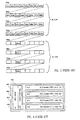
- three data blocks for example RLC blocks that are coded using various coding methods so that first two coded blocks can be transmitted, for example, using two radio bursts and the third coded block can be transmitted, for example, using eight radio bursts.
- Figure 5 shows the first two coded blocks 501 and 502, and the third coded block divided into two parts 511 and 512.
- the coded blocks are arranged to aggregated coded blocks in a method according to the first embodiment of the invention.
- the three coded blocks needing twelve radio bursts for transmission, are preferably arranged to three aggregated coded blocks.
- One of them contains the first two coded blocks (aggregated coded block 500 in Figure 5), and two of them (510 and 520 in Figure 5) contain each one part of the third coded block.
- the aggregated coded data block 500 contains two parts, each part being a complete coded data block.
- the aggregated coded data blocks 510 and 520 each carry one part, and the parts are partial coded data blocks.
- a header is added to the aggregated coded blocks.
- the header tells, for example, the coding of the data block(s) carried in the aggregated data block and/or the number of coded data blocks in the aggregated data block.
- An aggregated coded data block and its header are transmitted with the same radio bursts.
- the network codes data block related to many mobile stations and aggregates the coded data block to aggregated data block.
- a downlink aggregated data block may thus carry coded data blocks to many mobile stations.
- the header is usually transmitted using all data bursts used to transmit the aggregated coded data block.
- each mobile station In uplink direction each mobile station typically codes the data blocks it intends to send.
- the network may control the arrangement of the coded data blocks to aggregated coded data blocks, for example, by designating to each mobile station a certain number of radio bursts in the next uplink radio block. Thereafter each mobile station constructs a header to the coded block it intends to send and transmits the coded data block and the header using certain uplink radio bursts, typically those bursts that were designated to it by the network.
- a first mobile station sends the coded block 501 (the first part of aggregated coded data block 500), a second mobile station sends the coded block 502 (the second part of aggregated coded data block 500), and a third mobile station sends both the aggregated coded data blocks 510 and 520.
- the number of radio bursts per one data block for example a RLC block
- the number of radio bursts per RLC block is the same for each mobile station using a certain packet data channel, it is possible to signal this value to the mobile stations, for example, when a TBF is established. Let us first consider a case where the number of radio bursts per RLC block does not change dynamically nor between the TBFs using a certain packet data channel. In this case all mobile station using a certain downlink packet data channel knows the number of radio bursts using which a coded RLC block is transmitted.
- the network codes and interleaves the RLC block for a certain user and transmits it using, for example, two radio bursts.
- One radio block carries thus two RLC blocks in EGPRS in a method according to this second preferred embodiment of the invention. It is possible that different coding methods are used for the blocks, and therefore the information about the coding of each RLC block must be available at least to the receiving mobile station.
- the coding method can be indicated, for example, with the following methods.
- SB stealing bits
- Another way is to indicate the coding method implicitly. This can be done, because the coding method usually depends on the size of the MAC header. This MAC header is coded in a way that depends on the modulation scheme straightforwardly, and the actual transmitted data (for example, RLC block) is then coded with another coding scheme.
- a mobile station can determine the MAC header and the size of the MAC header without knowing the coding scheme that is used for the RLC block.
- the coding scheme used with each header size may be specified in standards, and therefore the mobile can determine the coding scheme of the RLC block(s) from the MAC header size.
- a mobile station collects the information carried by a radio block (step 601 in Figure 6). Thereafter it determines the coding, for example, from a certain string in the coded MAC header (step 602). When the coding is know, it can uncode the RLC blocks transmitted using the radio block (step 603). Thereafter, in step 605, the mobile station determines the downlink (DL) identifiers in the RLC blocks. Typically there is one connection identifier is each RLC block. This connection identifier can be, for example the TFI. When knowing the TFIs, the mobile station can decide (step 606) whether the RLC block is intended for it.
- DL downlink
- a mobile station may be prepared to receive only one RLC block in a radio block. It may try to uncode the two consequent coded RLC block assuming that it is uncoding only one RLC block. The result is that the structure of the uncoded data is most probably not the structure of a RLC block, and the possibly used error checking codes indicate that some error has taken place in the transmission. This situation can be avoided by a suitable selection of stealing bits in the coded MAC header. The value of the string can be selected so that the a mobile station, who can receive or transmit only one RLC block per radio block, does not recognize the coding. Then it does not even try to uncode the data in that radio block.
- Figure 7a shows a schematic drawing of a coded RLC/MAC block 700 according to the second preferred embodiment of the invention.
- the coded MAC header 701 is presented in a vertical direction.
- the USF field 702 of the MAC header is also presented in Figure 7.
- Figure 7 presents an example where the coded RLC/MAC block comprises two coded RLC blocks related to two different TFIs.
- the first coded RLC block is transmitted by the first two radio bursts of the radio block.
- the first burst carries a first part 703 of the coded information
- the second burst carries the second part 704.
- the second coded RLC block is transmitted similarly in two parts 705 and 706 using the last two radio bursts of the radio block.
- the coded information transmitted using the first two radio bursts (703, 704), i.e. the first coded RLC block, is the first part of the aggregated coded data block, corresponding to part 501 in Figure 5.
- the second coded RLC block is the second part of the aggregated coded data block.
- the number of radio bursts using which a coded RLC block is transmitted can be dynamically chosen from a set of values.
- information about the number of coded RLC blocks carried by a certain coded RLC/MAC block and which radio bursts are allocated for each coded RLC block is stated in the MAC header of the coded RLC/MAC block. Because the MAC header is longer, the amount of coded RLC data that can be transmitted using a radio block may be in this case somewhat smaller than when the number of radio bursts per coded RLC block is known by the mobile stations a priori.
- the size of the MAC header does not depend on how many coded RLC blocks the coded RLC/MAC block carries.
- One way is to place to each MAC header as many BId (Block Interleaving Downlink) indicators as there are radio bursts in the radio block.
- Figure 7b presents a coded RLC/MAC block 710 where the MAC header 711 comprises the USF field 702 and four BId indicators 751, 752, 753 and 754. The use of BId indicators is explained below using examples.
- Rectangle 713 carries the first coded RLC block, which is related to a TBF identifier with value TFI3.
- Rectangles 714 and 715 carry a second coded RLC block, related to TBF identifier with value TFI4.
- the rectangle 716 carries the third coded RLC block, related to a TBF identifier with value TFI5.
- the method 600 for receiving downlink coded data blocks works also in a situation, where the number of coded RLC blocks and the number of radio bursts allocated for each RLC block is stated in the coded RLC/MAC block.
- the BId indicators are determined in step 603. Thereafter the mobile station can infer the number of radio bursts per coded RLC block.
- Each coded RLC block is uncoded in step 604.
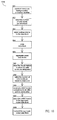
- FIG. 8 presents a flowchart of a method for transmitting coded downlink data blocks according to the second preferred embodiment of the invention.
- the network constructs a data block, for example a RLC block, that is to be sent to a mobile station.
- the receiving mobile station is identified with a connection identifier, for example with the TFI, in the data block.
- the number of radio bursts allocated for the data block is selected, for example based on the quality of service requirements or based on the transmission error probability.
- the coding method is selected in step 803. It is also possible that the coding method is selected first, and the choice of coding method dictates the number of radio bursts.
- the data block for example a RLC block, is coded in step 804.
- the network aggregates a suitable number of coded data blocks to a coded RLC/MAC block.
- a proper MAC header is added to the coded data block (step 806).
- the MAC header may comprise, for example, the BId indicators and possible bit strings indicating the coding of each RLC block.
- the aggregated coded data block is transmitted using a radio block.
- the number of radio bursts per a RLC block can be varied in the uplink direction. Let us first discuss the allocation of uplink radio bursts to the mobile station sharing the uplink packet data channel. To achieve backwards compatibility, it is necessary to keep an uplink identifier, in EGPRS the USF field, in the MAC header. In a method according to the third preferred embodiment of the invention, an uplink subidentifier is introduced. Some values of the uplink identifier are reserved for transmitting data using whole radio blocks. The rest of the values of the uplink identifier are used to indicate groups of mobile stations that can transmit coded data blocks using a varying number of radio bursts.
- the uplink subidentifier is then used to indicate a certain mobile station within the group which the uplink identifier indicates.
- An uplink identifier and an uplink subidentifier is given to each mobile station that is aiming to transmit coded data block using a varying number of radio blocks.
- Figure 7c presents an example of uplink identifiers (USF) and uplink subidentifiers (extUSF).
- USF uplink identifiers
- extUSF uplink subidentifiers
- the value of USF in the coded RLC/MAC block 720 is such that it refers to a group of mobile stations.
- the length of the extUSF identifiers may be, for example, two bits and there may be up to four mobile stations in the group a certain USF value specifies.
- the actual coded RLC blocks of the coded RLC/MAC block 720 are related to TBFs having identifiers TFI6 (rectangles 723, 724) and TFI7 (rectangles 725, 726). It is assumed that in the downlink direction the number of radio bursts per coded RLC block is two, similarly as in the example presented in Figure 6a.
- the size of the MAC header increases if a coded RLC/MAC block carries uplink subidentifiers, such as extUSFs. Even if the RLC/MAC block 720 carried only one coded RLC block (i.e. rectangles 723-726 each carry a part of the coded RLC block), a mobile station that is able to receive only one coded data block per radio block would probably not be able to uncode the RLC block. This is because it incorrectly assumes that the extUSF indicators are part of the coded RLC block. Downlink coded RLC/MAC blocks that contain uplink subidentifiers should carry coded RLC/MAC blocks only to mobile stations that can receive RLC/MAC blocks according to the invention.
- Figure 7d presents a second example of uplink identifiers (USF) and uplink subidentifiers (extUSF).
- USF uplink identifiers
- extUSF uplink subidentifiers
- one of the RLC blocks can be coded and interleaved in such a way that the coded RLC block can be transmitted using two radio bursts, and the other RLC block can be coded and interleaved in such a way that the coded RLC block can be transmitted using one radio burst. If three RLC blocks are transmitted, they can be processed all in the same way.
- the coded RLC/MAC block 730 comprises also BIu (Block Interleaving uplink) indicators 771, 772, 773 and 774.
- the USF and extUSF identifiers have a certain value in two sequential coded downlink RLC/MAC blocks, and all BIu indicators in these coded downlink RLC/MAC blocks have the value corresponding to eight radio bursts. If coded RLC blocks on a certain packet data channel are transmitted using fixed mobile-station-dependent numbers of radio bursts, then it is not necessary to transmit BIu indicators to the mobile stations in coded RLC/MAC blocks. This is especially true, if all coded data blocks on a certain data channel are transmitted using a certain number of radio bursts.
- the resulting uncoded data most probably does not have the structure of a RLC block, and the mobile station has to decide whether a transmission error occurred or whether the coded RLC block was not intended for it. This decision can be made, for example, with the help of a check sum that the network calculates over the coded RLC blocks in a RLC/MAC block and places in the MAC header.
- Figure 9 presents the flowchart of a method for determining the allocation of an uplink packet data channel according to the third preferred embodiment of the invention.
- a mobile station can determine, if it is its turn to transmit data over the uplink packet data channel.
- a mobile station may be given only the uplink identifier, for example USF, or both the uplink identifier and the uplink subidentifier, for example extUSF (step 901).
- step 902 the mobile station receives a coded data block, for example a coded RLC/MAC block, transmitted using a radio block. Thereafter it determines the uplink (UL) identifier in the coded MAC header (step 903). In step 904 the mobile station checks if it has a UL subidentifier.
- a coded data block for example a coded RLC/MAC block
- the mobile station checks if the UL identifier in the coded downlink data block is equal to its UL identifier (step 905). If it is, then the mobile station knows the next uplink radio block is designed to it (step 906). If it is not, then the mobile station has to wait for the next downlink radio block related to the packet data channel. If a mobile station can transmit and receive only coded data that is transmitted using whole radio blocks, it has not been given an UL subidentifier. Therefore it uses only the steps 901-906 of the flowchart.
- the mobile station If the mobile station has a subidentifier, it first checks if the UL identifier in the coded downlink data block is equal to its UL identifier (step 907). If it is not equal, no radio bursts in the next uplink radio block are designated for the mobile station and it has to wait for the next coded downlink data block. If it is equal, then the mobile station determines the UL subidentifiers in the received coded data block (step 908).
- the mobile station waits for the next coded data block. If at least some of the UL subidentifiers are equal to the mobile station's UL subidentifier, then it determines the number of radio bursts designated to it and determines the interleaving lengths (step 910).
- the interleaving lengths can be determined, for example, using BIu indicators or using signaling information.
- step 911 the mobile station codes and interleaves the data block or data blocks it is allowed to send in the next uplink radio block.
- step 912 is transmits the coded data blocks using the radio bursts that have been designated to it.
- the flowchart in Figure 10 presents a method 1000 for transmitting coded downlink data blocks according to the third preferred embodiment of the invention.
- the method 1000 starts with similar step 801-805 as the method 800. These steps are related to the information that is transmitted in the downlink direction.
- the network divides the radio bursts in the next uplink radio blocks to certain group of mobile stations.
- the group of mobile stations is defined with an UL identifier and the individual mobile station within the group with an UL subidentifier.
- the number of radio bursts per each data block is selected. This can be indicated, for example, with BIu indicators.
- step 1003 a MAC header that comprises the necessary UL identifier and UL subidentifiers and possible BIu indicators is constructed.
- step 807 and 808 the MAC header is added to the aggregated coded data block and transmitted to mobile stations.
- a mobile station When a mobile station transmits packet data in the uplink direction, it may use a method similar to the method 1000. It first constructs the data block it intends to send. Thereafter is figures out the number of radio bursts the network has allocated to it using the method 900, for example. It further detects the information about the interleaving, for example the BIu indicators. It selects a suitable coding and interleaving method and thereafter transmits the coded data block using those radio bursts in the uplink radio block that were designated to it.
- the uplink packet data channel is allocated to the users with some other means than by using uplink identifiers and subidentifiers, it is still possible to use the bursts-by-burst allocation according to the invention in the uplink direction. Irrespective of how a mobile stations knows/decides when to transmit packet data, each mobile station may use a varying number of radio bursts when transmitting a data block. The connection identifier in the data block will tell the network which mobile station sent the data block.
- the network informs the mobile stations of their turns to use the uplink packet data channel, the network knows which mobile station is transmitting data and how many radio bursts is uses a coded data block. Therefore it is not necessary to carry information about the number of radio bursts per coded uplink block in the uplink coded block itself.
- the MAC header of the uplink coded block may change, however, compared to the current EGPRS specification, because when a mobile station is transmitting a coded RLC/MAC block using a whole radio block it can code the MAC header over the whole radio block.
- the uplink radio bursts are designated on a burst-by-burst basis, it is probably more preferable to code the MAC header over the same number of radio bursts that is used to transmit a coded RLC/MAC block.
- the number of radio bursts per a coded data block can be varied in both uplink and downlink directions.
- the network may use the method 1000 when transmitting the downlink coded data blocks and information about the designation of the uplink radio bursts.
- the mobile station may use methods 600 and 900 simultaneously. It can, for example, uncode the information in the coded downlink data block before returning back to step 902, i.e. after step 905, 906, 907, 909 or 912.
- FIG. 7e presents an example of a coded data block according to the fourth preferred embodiment of the invention.
- coded packet data can be transmitted using coded RLC/MAC blocks 400 and 720.
- RLC/MAC blocks 720 carry downlink information to mobile stations that can receive coded data block transmitted using a varying number of radio bursts. They can contain up to four RLC blocks for various mobile stations in EGPRS.
- RLC/MAC block 400 on the other hand, can transmit data to all mobile stations, but it carries only one RLC block at a time.
- the uplink radio bursts can be designated on a block-by-block basis (using a suitable value of the UL identifier) or an a burst-by-burst basis (using suitable values of the UL identifier and the UL subidentifier).
- a RLC/MAC block 400 can carry only an UL identifier, and this identifier should not refer to a group of mobile stations.
- a RLC/MAC block 720 may carry both the UL identifier and UL subidentifier.
- the UL identifier in a RLC/MAC block 720 may refer to a single mobile station, in which case the UL subidentifier values are meaningless and the whole next uplink radio block is allocated for the mobile station having the UL identifier.
- the UL identifier is a RLC/MAC block 720 may also refer to a group of mobile stations, in which case the UL subidentifiers indicate the allocation of the uplink radio bursts to the mobile stations belonging to the group.
- Downlink data to mobile station A may be transmitted using RLC/MAC blocks 400 which each carry one RLC block to mobile station A.
- the USF field may be set to 1.
- Downlink data to mobile stations B and C may be transmitted using RLC/MAC blocks 720, which each carry two coded RLC blocks (one for mobile station B and one for mobile station C).
- the USF fields is 2 and the four extUSF fields have values 1, 1, 2 and 2.
- every other RLC/MAC block is a RLC/MAC block 400 and every other is a RLC/MAC block 720.
- Table 1 below gives an example of coding of the extUSF identifier.
- the extUSF is two bits long.
- the possible values of the extUSF are represented in the left-most column of the table.
- b1, b2, b3 and b4 refer to the burst number in a radio block that contains four radio bursts.
- the coding suggested in Table 1 depends only on the modulation which is used. In EGPRS either GMSK or 8-PSK is used.
- the possible BId and BIu indicators can be coded similarly, if their length is also 2 bits.
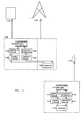
- Figure 11 presents a mobile station 1110 according to the invention.
- the mobile station 1110 comprises a block 1112 responsible for selecting the number of radio bursts using which a certain data block is transmitted. The selection of bursts in block 1112 may happen by detecting the number of bursts the network has designated for the mobile station.
- the mobile station further comprises a mapping block 1113 which maps the data block to the available bursts, for example performing a suitable coding. Thereafter the transceiver block 114 transmits the radio bursts which carry information related to the data block.
- the communication block 1111 is responsible for communication with upper protocol layers, and the data block which is to be transmitted is usually received from upper layer protocols.
- the radio bursts are received in the mobile station using the transceiver 1114.
- Detection block 1115 is responsible for detecting the radio bursts and their number that are related to a certain data block.
- construction block 1116 the data block is constructed, for example the data carried with a certain number of radio bursts is uncoded. Thereafter the data block is supplied to the upper protocol layers.
- the blocks 1112, 1113, 1115 and 1116 are usually part of the second and third protocol layers. They can be implemented, for example, using processors and suitable software.
- the mobile station 1110 may support any method according to the invention.
- the arrangement 1120 according to the invention has similar block as a mobile station 1110 according to the invention. It has a communication block 1121 for communication with upper protocol layers and selection block 1122 for selecting the number of radio bursts per data block, for example, based on the amount of transmission errors. These blocks are typically situated in a controlling network element 1140, for example in a Packet Control Unit (PCU) of the (E)GPRS system. The mapping of data block to radio bursts (block 1123) is usually done also in the PCU.
- PCU Packet Control Unit
- the mapping of data block to radio bursts (block 1123) is usually done also in the PCU.
- the transceiver 1124 is in the base station 1130, and when the radio bursts are received, the entity responsible of constructing the data block (in block 1126, usually this block resides in the PCU) needs to know the number of radio bursts used to transmit the block. The number can be detected in block 1125, for example, from the header of the data block, but it can also be known a priori. If the network designates the uplink radio bursts to the mobile stations, it may assume that the uplink data it receives is transmitted by the mobile stations according to the designation.
- the blocks within the arrangement 1120 according to the invention may also be divided in a different way among the network elements. It is also possible that the whole arrangement is implemented in one network element.
- the arrangement or network elements according to the invention may support, for example, any method according to the preferred embodiments of the invention discussed above.
- cellular system refers generally to any telecommunications system which enables a wireless communication connection between a mobile station and the fixed parts of the system when the user of the mobile station is moving within the service area of the system.
- GSM Global System for Mobile communications
- the invention also applies to the next or third generation of mobile telecommunications systems, such as a system known as the UMTS (Universal Mobile Telecommunications System) which currently undergoes standardization.
- UMTS Universal Mobile Telecommunications System
- EGPRS is used as an example of a system where a method according to the invention can be implemented.
- the methods according to the invention are not restricted to those used in EGPRS or in GPRS; a method according to the invention can be applied also in other wireless packet data networks .
Landscapes
- Engineering & Computer Science (AREA)
- Computer Networks & Wireless Communication (AREA)
- Signal Processing (AREA)
- Quality & Reliability (AREA)
- Mobile Radio Communication Systems (AREA)
Applications Claiming Priority (2)
| Application Number | Priority Date | Filing Date | Title |
|---|---|---|---|
| FI992232 | 1999-10-15 | ||
| FI992232A FI109438B (fi) | 1999-10-15 | 1999-10-15 | Menetelmä tiedon siirtämiseksi pakettidatakanavalla |
Publications (2)
| Publication Number | Publication Date |
|---|---|
| EP1093315A2 true EP1093315A2 (de) | 2001-04-18 |
| EP1093315A3 EP1093315A3 (de) | 2005-12-07 |
Family
ID=8555457
Family Applications (1)
| Application Number | Title | Priority Date | Filing Date |
|---|---|---|---|
| EP00660141A Withdrawn EP1093315A3 (de) | 1999-10-15 | 2000-08-25 | Verfahren zur Datenübertragung auf einem Paketdatenkanal |
Country Status (3)
| Country | Link |
|---|---|
| US (1) | US7145896B1 (de) |
| EP (1) | EP1093315A3 (de) |
| FI (1) | FI109438B (de) |
Cited By (12)
| Publication number | Priority date | Publication date | Assignee | Title |
|---|---|---|---|---|
| WO2002093817A1 (en) * | 2001-05-01 | 2002-11-21 | Telefonaktiebolaget Lm Ericsson (Publ) | Flexible layer one configuration for radio to plmn interface |
| EP1326454A1 (de) * | 2002-01-08 | 2003-07-09 | Motorola, Inc. | Verfahren zur dynamischen Zuweisung in Abwärtsrichtung in Mobilkommunikationssystemen |
| US7103020B2 (en) | 2001-05-01 | 2006-09-05 | Telefonaktiebolaget Lm Ericsson (Publ) | PLMN radio interface with upper layer supervision of layer one transport channels |
| EP1720276A1 (de) * | 2001-05-01 | 2006-11-08 | Telefonaktiebolaget LM Ericsson (publ) | Flexible Schicht1 Konfiguration für Funk zu PLMN Schnittstelle |
| US7188300B2 (en) | 2001-05-01 | 2007-03-06 | Telefonaktiebolaget Lm Ericsson (Publ) | Flexible layer one for radio interface to PLMN |
| CN1307841C (zh) * | 2003-10-29 | 2007-03-28 | 中兴通讯股份有限公司 | 在基站内部传输实时业务数据的方法 |
| SG134172A1 (en) * | 2001-05-14 | 2007-08-29 | Interdigital Tech Corp | Physical channel configuration signaling procedures |
| US7286509B2 (en) | 2001-05-14 | 2007-10-23 | Interdigital Technology Corporation | Physical channel configuration signaling procedures |
| US20140243037A1 (en) * | 2013-02-26 | 2014-08-28 | Qualcomm Incorporated | Transmitting power optimization on a wireless communication device |
| WO2016122371A1 (en) * | 2015-01-27 | 2016-08-04 | Telefonaktiebolaget Lm Ericsson (Publ) | Transmitting device, receiving device, controlling node, and methods therein, for transmitting a block to the receiving device |
| EP2606699A4 (de) * | 2010-08-19 | 2016-08-24 | Nokia Technologies Oy | Verfahren und vorrichtung für multiplex-verwendung einer ressource bei einem übertragungsmedium |
| EP3863370A1 (de) * | 2020-02-04 | 2021-08-11 | Institut für Rundfunktechnik GmbH | Mobilfunknetz-broadcasting |
Families Citing this family (10)
| Publication number | Priority date | Publication date | Assignee | Title |
|---|---|---|---|---|
| KR100802618B1 (ko) * | 2001-07-07 | 2008-02-13 | 엘지전자 주식회사 | 무선통신시스템에서 이동국 식별자 설정방법 및 장치 |
| DE502004001672D1 (de) * | 2003-02-28 | 2006-11-16 | Siemens Ag | Verfahren zur zuweisung funktechnischer ressourcen für eine datenübertragung in einem funkkommunikationssystem |
| US7444136B1 (en) * | 2003-06-26 | 2008-10-28 | At&T Mobility Ii Llc | System and method for providing information services to subscribers in a GPRS network |
| US20060039271A1 (en) * | 2004-08-18 | 2006-02-23 | Ping Li | Power Controlled Interleave-division Multiple-access Wireless Communication Systems |
| CN101297561B (zh) * | 2005-11-01 | 2011-04-06 | 艾利森电话股份有限公司 | 无线电通信系统中的方法和装置 |
| EP2028772B1 (de) * | 2007-07-31 | 2010-06-23 | Research In Motion Limited | Datenburstkommunikationsverfahren zur Verwendung bei steigendem Datendurchsatz zu mobilen Kommunikationsvorrichtungen |
| US7957418B2 (en) * | 2007-07-31 | 2011-06-07 | Research In Motion Limited | Data burst communication techniques for use in increasing data throughput to mobile communication devices |
| KR101818279B1 (ko) | 2010-08-03 | 2018-01-12 | 삼성전자주식회사 | 무선 네트워크 시스템에서 패킷 데이터 유닛들을 송신하는 방법 및 장치 |
| CN102457977B (zh) * | 2010-10-14 | 2016-08-10 | 华为技术有限公司 | 一种数据调度方法及系统以及相关设备 |
| WO2012115576A1 (en) * | 2011-02-25 | 2012-08-30 | Telefonaktiebolaget L M Ericsson (Publ) | Method and arrangement for resolving a temporary block flow |
Family Cites Families (24)
| Publication number | Priority date | Publication date | Assignee | Title |
|---|---|---|---|---|
| US5477541A (en) * | 1989-09-29 | 1995-12-19 | White; Richard E. | Addressing technique for storing and referencing packet data |
| US5495482A (en) * | 1989-09-29 | 1996-02-27 | Motorola Inc. | Packet transmission system and method utilizing both a data bus and dedicated control lines |
| US6647000B1 (en) * | 1999-05-28 | 2003-11-11 | Telefonaktiebolaget Lm Ericsson (Publ) | Methods and apparatus for performing slot hopping of logical control channels in wireless communications systems |
| EP0671824B1 (de) * | 1994-03-07 | 2004-05-19 | Siemens Aktiengesellschaft | Verfahren und Anordnung zur Übertragen von block kodierten Informationen über mehrere Kanäle in einem digitalen mobilen Funksystem |
| CN1086531C (zh) * | 1994-12-09 | 2002-06-19 | 英国电讯有限公司 | 多处理器环境运行的进程间的数据包传送方法 |
| US5742592A (en) * | 1995-09-01 | 1998-04-21 | Motorola, Inc. | Method for communicating data in a wireless communication system |
| US5606561A (en) * | 1995-07-28 | 1997-02-25 | Motorola, Inc. | Method, device/microprocessor, and computer software for providing packet fragmentation for fair, efficient downlink transmission with low packet delay |
| US5751704A (en) | 1996-03-01 | 1998-05-12 | Lucent Technologies Inc. | Technique for minimizing the variance of interference in packetized interference-limited wireless communication systems |
| US5812547A (en) * | 1996-08-22 | 1998-09-22 | At&T Corp. | System and method for dynamic time division access |
| DE19638814A1 (de) * | 1996-09-20 | 1998-03-26 | Bosch Gmbh Robert | Verfahren zur drahtlosen Übertragung von digitalen Daten |
| EP0990351B1 (de) * | 1997-06-17 | 2003-03-26 | Siemens Aktiengesellschaft | Verfahren, mobilstation und basisstation zur signalübertragung |
| EP1523122A3 (de) * | 1997-07-09 | 2007-04-25 | Matsushita Electric Industrial Co., Ltd. | Datenübertragung zwischen einer zentralen Einrichtung und einer Mehrzahl an entfernten Einrichtungen |
| US6208663B1 (en) * | 1997-08-29 | 2001-03-27 | Telefonaktiebolaget Lm Ericsson (Publ) | Method and system for block ARQ with reselection of FEC coding and/or modulation |
| FI106088B (fi) * | 1997-09-12 | 2000-11-15 | Nokia Networks Oy | Datansiirtomenetelmä yleisen pakettiradiopalvelun (General Packet Radio Service) verkko-osan ja tilaajapäätelaitteen välillä |
| US6363058B1 (en) * | 1997-09-24 | 2002-03-26 | Telefonaktiebolaget L M Ericsson (Publ) | Multi-service handling by a single mobile station |
| US6501745B1 (en) * | 1998-02-13 | 2002-12-31 | Telefonaktiebolaget Lm Ericsson (Publ) | Method for variable block scheduling indication by an uplink state flag in a packet data communication system |
| SE522587C2 (sv) * | 1998-02-16 | 2004-02-24 | Ericsson Telefon Ab L M | Förfarande och mottagaranordning för mottagning av upprepade skurar i ett radiokommunikationssystem |
| CA2278904A1 (en) * | 1998-09-02 | 2000-03-02 | Lucent Technologies Inc. | Mobile terminal and base station in a packet radio services network |
| US20010056560A1 (en) * | 1998-10-08 | 2001-12-27 | Farooq Khan | Method and system for measurement based automatic retransmission request in a radiocommunication system |
| US6865233B1 (en) * | 1999-02-19 | 2005-03-08 | Telefonaktiebolaget Lm Ericsson (Publ) | Method and system for control signalling enabling flexible link adaptation in a radiocommunication system |
| US6584084B1 (en) * | 1999-03-01 | 2003-06-24 | Nortel Networks Ltd. | Expanded carrier capacity in a mobile communications system |
| US6438115B1 (en) * | 1999-03-08 | 2002-08-20 | Telefonaktiebolaget L M Ericsson (Publ) | High speed data communication system and method |
| US6259744B1 (en) * | 1999-06-01 | 2001-07-10 | Motorola, Inc. | Method and apparatus for mapping bits to an information burst |
| US6772112B1 (en) * | 1999-12-10 | 2004-08-03 | Lucent Technologies Inc. | System and method to reduce speech delay and improve voice quality using half speech blocks |
-
1999
- 1999-10-15 FI FI992232A patent/FI109438B/fi not_active IP Right Cessation
-
2000
- 2000-08-25 EP EP00660141A patent/EP1093315A3/de not_active Withdrawn
- 2000-10-12 US US09/689,447 patent/US7145896B1/en not_active Expired - Fee Related
Cited By (28)
| Publication number | Priority date | Publication date | Assignee | Title |
|---|---|---|---|---|
| CN1311654C (zh) * | 2001-05-01 | 2007-04-18 | 艾利森电话股份有限公司 | 用于无线电到plmn的无线电接口的灵活的第一层配置 |
| US7103020B2 (en) | 2001-05-01 | 2006-09-05 | Telefonaktiebolaget Lm Ericsson (Publ) | PLMN radio interface with upper layer supervision of layer one transport channels |
| EP1720276A1 (de) * | 2001-05-01 | 2006-11-08 | Telefonaktiebolaget LM Ericsson (publ) | Flexible Schicht1 Konfiguration für Funk zu PLMN Schnittstelle |
| US7188300B2 (en) | 2001-05-01 | 2007-03-06 | Telefonaktiebolaget Lm Ericsson (Publ) | Flexible layer one for radio interface to PLMN |
| WO2002093817A1 (en) * | 2001-05-01 | 2002-11-21 | Telefonaktiebolaget Lm Ericsson (Publ) | Flexible layer one configuration for radio to plmn interface |
| SG134172A1 (en) * | 2001-05-14 | 2007-08-29 | Interdigital Tech Corp | Physical channel configuration signaling procedures |
| US7286509B2 (en) | 2001-05-14 | 2007-10-23 | Interdigital Technology Corporation | Physical channel configuration signaling procedures |
| US8169979B2 (en) | 2001-05-14 | 2012-05-01 | Interdigital Technology Corporation | TDMA/CDMA user equipment |
| US8509195B2 (en) | 2001-05-14 | 2013-08-13 | Interdigital Technology Corporation | TDMA/CDMA user equipment |
| US10334593B2 (en) | 2001-05-14 | 2019-06-25 | Interdigital Technology Corporation | Hybrid apparatus using physical channels |
| US9674834B2 (en) | 2001-05-14 | 2017-06-06 | Interdigital Technology Corporation | Hybrid apparatus using physical channels |
| EP1326454A1 (de) * | 2002-01-08 | 2003-07-09 | Motorola, Inc. | Verfahren zur dynamischen Zuweisung in Abwärtsrichtung in Mobilkommunikationssystemen |
| CN1307841C (zh) * | 2003-10-29 | 2007-03-28 | 中兴通讯股份有限公司 | 在基站内部传输实时业务数据的方法 |
| EP2606699A4 (de) * | 2010-08-19 | 2016-08-24 | Nokia Technologies Oy | Verfahren und vorrichtung für multiplex-verwendung einer ressource bei einem übertragungsmedium |
| WO2014133821A1 (en) * | 2013-02-26 | 2014-09-04 | Qualcomm Incorporated | Transmitting power optimization on a wireless communication device |
| US20140243037A1 (en) * | 2013-02-26 | 2014-08-28 | Qualcomm Incorporated | Transmitting power optimization on a wireless communication device |
| US9680609B2 (en) | 2015-01-27 | 2017-06-13 | Telefonaktiebolaget Lm Ericsson (Publ) | Transmitting device, receiving device, controlling node, and methods therein, for transmitting a block to the receiving device |
| WO2016122371A1 (en) * | 2015-01-27 | 2016-08-04 | Telefonaktiebolaget Lm Ericsson (Publ) | Transmitting device, receiving device, controlling node, and methods therein, for transmitting a block to the receiving device |
| RU2639951C1 (ru) * | 2015-01-27 | 2017-12-25 | Телефонактиеболагет Лм Эрикссон (Пабл) | Передающее устройство, приемное устройство, узел управления и относящиеся к ним способы для передачи блока в приемное устройство |
| US9974082B2 (en) | 2015-01-27 | 2018-05-15 | Telefonaktiebolaget Lm Ericsson (Publ) | Transmitting device, receiving device, controlling node, and methods therein, for transmitting a block to the receiving device |
| US10098126B2 (en) | 2015-01-27 | 2018-10-09 | Telefonaktiebolaget Lm Ericsson (Publ) | Transmitting device, receiving device, controlling node, and methods therein, for transmitting a block to the receiving device |
| AU2015380711B2 (en) * | 2015-01-27 | 2018-11-08 | Telefonaktiebolaget Lm Ericsson (Publ) | Transmitting device, receiving device, controlling node, and methods therein, for transmitting a block to the receiving device |
| EP3425831A1 (de) * | 2015-01-27 | 2019-01-09 | Telefonaktiebolaget LM Ericsson (publ) | Übertragungsvorrichtung, empfangsvorrichtung, steuerungsknoten und verfahren darin zur übertragung eines blocks an die empfangsvorrichtung |
| CN106576017A (zh) * | 2015-01-27 | 2017-04-19 | 瑞典爱立信有限公司 | 用于向接收设备传输块的传输设备、接收设备、控制节点以及其中的方法 |
| US10356795B2 (en) | 2015-01-27 | 2019-07-16 | Telefonaktiebolaget Lm Ericsson (Publ) | Transmitting device, receiving device, controlling node, and methods therein, for transmitting a block to the receiving device |
| CN106576017B (zh) * | 2015-01-27 | 2019-09-24 | 瑞典爱立信有限公司 | 用于向接收设备传输块的传输设备、接收设备、控制节点以及其中的方法 |
| EP3863370A1 (de) * | 2020-02-04 | 2021-08-11 | Institut für Rundfunktechnik GmbH | Mobilfunknetz-broadcasting |
| WO2021156234A1 (en) * | 2020-02-04 | 2021-08-12 | Institut Für Rundfunktechnik Gmbh I. L. | Cellular network broadcasting |
Also Published As
| Publication number | Publication date |
|---|---|
| FI109438B (fi) | 2002-07-31 |
| US7145896B1 (en) | 2006-12-05 |
| FI19992232L (fi) | 2001-04-16 |
| EP1093315A3 (de) | 2005-12-07 |
Similar Documents
| Publication | Publication Date | Title |
|---|---|---|
| US7145896B1 (en) | Method for transmitting data on a packet data channel | |
| EP1078485B1 (de) | Datenübertragung über eine kommunikationsverbindung mit variabler datenrate | |
| EP1921812B1 (de) | Verfahren und Vorrichtung zur Planung einer Datenübertragung in einem mobilen Kommunikationssystem mit Paketdatendienst | |
| AU784505B2 (en) | Advanced method and arrangement for transferring information in a packet radio service | |
| KR100985043B1 (ko) | 무선 통신 시스템에서의 정보 맵핑 | |
| CN101444031B (zh) | 在edge兼容的系统内的arq过程中安全地传输短ack/nack位图的方法 | |
| CN100418310C (zh) | 用于在分组通信系统中调度上行链路速率的方法及设备 | |
| Seurre et al. | GPRS for mobile Internet | |
| US7197024B2 (en) | Telecommunications system having layered protocol with delimiter of payload | |
| US7751441B2 (en) | Method for exchanging data packets between two service providers of a radiotelephony transmission system | |
| EP2220889B1 (de) | System und verfahren für einphasenzugang in einem kommunikationssystem | |
| JP2009534917A (ja) | 無線通信システムにおける肯定確認応答と否定確認応答とを送信する方法、通信エンティティ、及びシステム | |
| CA2541630C (en) | A method and a device for reconfiguration in a wireless system | |
| KR20100034666A (ko) | 비정상적 상황을 처리하는 이동국 | |
| WO2006110072A1 (en) | Mac header for enhanched uplink multiplexing | |
| EP1386436B1 (de) | Konfiguration der physicalischen schicht für eine funk schnittstelle | |
| CN1418038A (zh) | 在无线通信系统中传输信号的方法 | |
| EP1137215A1 (de) | Bitratenoptimierung in einem zellularen Kommunikationssystem | |
| WO2002030137A1 (en) | Method and arrangement in a communication system for connecting a gprs radio access network to a umts core network | |
| CA2799510A1 (en) | A method and a device for reconfiguration in a wireless system | |
| CN101335926A (zh) | 用于在无线系统中进行重新配置的方法和设备 |
Legal Events
| Date | Code | Title | Description |
|---|---|---|---|
| PUAI | Public reference made under article 153(3) epc to a published international application that has entered the european phase |
Free format text: ORIGINAL CODE: 0009012 |
|
| AK | Designated contracting states |
Kind code of ref document: A2 Designated state(s): AT BE CH CY DE DK ES FI FR GB GR IE IT LI LU MC NL PT SE |
|
| AX | Request for extension of the european patent |
Free format text: AL;LT;LV;MK;RO;SI |
|
| RAP1 | Party data changed (applicant data changed or rights of an application transferred) |
Owner name: NOKIA CORPORATION |
|
| PUAL | Search report despatched |
Free format text: ORIGINAL CODE: 0009013 |
|
| AK | Designated contracting states |
Kind code of ref document: A3 Designated state(s): AT BE CH CY DE DK ES FI FR GB GR IE IT LI LU MC NL PT SE |
|
| AX | Request for extension of the european patent |
Extension state: AL LT LV MK RO SI |
|
| AKX | Designation fees paid | ||
| REG | Reference to a national code |
Ref country code: DE Ref legal event code: 8566 |
|
| STAA | Information on the status of an ep patent application or granted ep patent |
Free format text: STATUS: THE APPLICATION IS DEEMED TO BE WITHDRAWN |
|
| 18D | Application deemed to be withdrawn |
Effective date: 20060608 |