EP1093712B1 - Schneidvorrichtung einer landwirtschaftlichen Erntebergungsmaschine - Google Patents
Schneidvorrichtung einer landwirtschaftlichen Erntebergungsmaschine Download PDFInfo
- Publication number
- EP1093712B1 EP1093712B1 EP00121540A EP00121540A EP1093712B1 EP 1093712 B1 EP1093712 B1 EP 1093712B1 EP 00121540 A EP00121540 A EP 00121540A EP 00121540 A EP00121540 A EP 00121540A EP 1093712 B1 EP1093712 B1 EP 1093712B1
- Authority
- EP
- European Patent Office
- Prior art keywords
- cutting device
- blades
- knife
- cross member
- sensor
- Prior art date
- Legal status (The legal status is an assumption and is not a legal conclusion. Google has not performed a legal analysis and makes no representation as to the accuracy of the status listed.)
- Expired - Lifetime
Links
Images



Classifications
-
- A—HUMAN NECESSITIES
- A01—AGRICULTURE; FORESTRY; ANIMAL HUSBANDRY; HUNTING; TRAPPING; FISHING
- A01F—PROCESSING OF HARVESTED PRODUCE; HAY OR STRAW PRESSES; DEVICES FOR STORING AGRICULTURAL OR HORTICULTURAL PRODUCE
- A01F15/00—Baling presses for straw, hay or the like
- A01F15/08—Details
- A01F15/10—Feeding devices for the crop material e.g. precompression devices
- A01F15/106—Feeding devices for the crop material e.g. precompression devices for round balers
-
- A—HUMAN NECESSITIES
- A01—AGRICULTURE; FORESTRY; ANIMAL HUSBANDRY; HUNTING; TRAPPING; FISHING
- A01F—PROCESSING OF HARVESTED PRODUCE; HAY OR STRAW PRESSES; DEVICES FOR STORING AGRICULTURAL OR HORTICULTURAL PRODUCE
- A01F15/00—Baling presses for straw, hay or the like
- A01F15/08—Details
- A01F15/10—Feeding devices for the crop material e.g. precompression devices
- A01F2015/107—Means for withdrawing knives, rotor or walls of the feeding chamber in case of plugging or congestion
-
- A—HUMAN NECESSITIES
- A01—AGRICULTURE; FORESTRY; ANIMAL HUSBANDRY; HUNTING; TRAPPING; FISHING
- A01F—PROCESSING OF HARVESTED PRODUCE; HAY OR STRAW PRESSES; DEVICES FOR STORING AGRICULTURAL OR HORTICULTURAL PRODUCE
- A01F15/00—Baling presses for straw, hay or the like
- A01F15/08—Details
- A01F15/10—Feeding devices for the crop material e.g. precompression devices
- A01F2015/108—Cutting devices comprising cutter and counter-cutter
Definitions
- the invention relates to a cutting device of a agricultural harvesting machine with several juxtaposed knives between at least two positions are adjustable.
- DE-A1-197 17 542 discloses a cutting device for a agricultural harvester, z. B. a round baler.
- This cutting device is equipped with an electronic, equipped with optical or mechanical sensor, which detects if some knives are not in the cutting position and thus the number of cutting blades has been changed. With this information, the pressure for adjusting all Knife controlled to ensure that they are not too high correct avoidance resistance when foreign bodies strike on the one hand and not too low evasion resistance during On the other hand.
- At least one single knife not in its intended position this may be the cutting position or one Be inoperative position.
- the signal from the sensor can then be used in a variety of ways, to the wrong position to point out a knife. So a warning can be made a machine operation interrupted, an engagement movement of Messers undertaken or similar activity.
- the sensor can be detected by motion detectors or contacts Detect the position of each individual knife separately.
- a simple, rugged, and cost effective design of a Sensors consists in the use of a traverse, i. one Component that spans all the knives and one wrong positioned knife deflected, actuated or acted upon becomes.
- a traverse can be a wire, a steel rope, a Chain, a rod or the like, each strong are curious and on almost any touch one Press switch that sends a corresponding signal, possibly only by a power interruption.
- the connection between the sensor and the knife or a the knife in its position holding actuator can be done by a constant direct investment, or only after the Knife or the actuator a specific, in particular very short, has traveled way.
- the traverse can be flexible as wire, rope, chain or The like trained and always be so curious that a moving knife moves the traverse. Such flexible traverse can also have an irregular course of Knives or their control elements follow.
- a switch is sufficient, the z. Legs Traction movement on the Traverse notes. With several switches can z. B. in a rigid crosshead a deflection to the End pages or tapped in the middle, so that a safe signal can be detected when the crosshead moved differently far.
- the energy flow can take the form of a light barrier, from Sound waves, a current flow or the like realized become what is possible with commercial means.
- the sensor can be used to provide a warning device, e.g. B. to activate a lamp or horn, so that a Operator on a malposition of a knife is pointed out. But it can also interrupt the operation or activate a device that is the wrong one Knife or all knives moved to the operating position.
- a warning device e.g. B. to activate a lamp or horn
- Figure 1 shows a harvesting machine 10 with a Cutting device 12 according to the invention.
- the harvesting machine 10 is in the form of a Round baler running, but could also a loader, a large baler and the like, in which the is to be comminuted good.
- the harvesting machine 10 is of known type and includes a frame 14 that extends over wheels 16 on the ground supported and by means of a drawbar 18 to a not shown Towing vehicle can be attached.
- the frame 14 also contributes a compression chamber 20 which is surrounded by rollers 22 and a Inlet 24 has.
- the rollers 22 are on a circular line arranged and extend in part vertically pivoting tailgate 26 and the other part in a rigid Housing 28. At the bottom of the housing 28 and the inlet 24th upstream there is a crop receiver 30, the downstream the cutting device 12 follows.
- the task of the harvesting machine 10 is on the Ground crop, mostly grass, hay or straw, by means of receive the Gutauf choirs 30, it by means of Cutting device 12 into small pieces and into the Press chamber 20 to promote where it is a compact bale is pressed. By opening the tailgate 26 is the Bale discharged to the ground and can be further processed become.
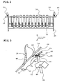
- the cutting device 12 is essentially also of known structure and includes a frame 32, a conveying surface 34, knife 36, actuators 38 and a sensor 40th
- the frame 32 is fixed to the housing 28 and carries a first axis 42, which extends across the width of the cutting device 12 extends.
- a second axis 44 extending parallel thereto serves the pivotal receiving the adjusting elements 38th
- the frame 32 in the embodiment according to the figures 2 to 5 on both sides oblong holes 46th intended.
- the conveying surface 34 extends over the entire width and Length of the knife 36 and guides the crop on its way from the crop receiver 30 to the inlet 24.
- the conveying surface 34 is essentially formed as a sheet that is not closer designated slots through which the knife 36th extend. In a working position shown in Figure 3 the blades 36 extend over their entire length the slots, in a shown in Figure 5 Inoperative position, the knife 36 extend almost completely not through the slots. While the conveying surface 34 in straight form, it can also be curved.
- the blades 36 are of known construction and have a Cutting edge 48, a holding opening 50 and a recess 52nd on.
- the blades 36 are laterally spaced with their Holding opening 50 placed on the axis 42 and can around this between their operating position and their inoperative position swing.
- the shape of the blades 36 substantially corresponds a right-angled triangle.
- the cutting edge 48 is concavely bent and points to the Conveying surface 34. Given the triangular shape of the knife 36 the cutting edge 48 comes to the position of the hypotenuse.
- the holding opening 50 is located in the view of the Drawing (Fig. 3 and Fig. 5) left lower corner region and is suitable to overlap the axis 42.
- the recess 52 is located in the view of the Drawing (Fig. 3 and Fig. 5) right upper corner area and is suitable to receive a roller 54 of the adjusting element 38 and to hold up to a certain resistance.
- Each knife 36 is associated with an actuator 38, the serves to keep the knife 36 in its operating position or swing back, or that can be put in a position in the knife 36 in the desired manner the May occupy a non-operational position.
- the actuator 38 is spring-loaded in a manner not shown, that the roller 54th always penetrates into the recess 52. Acts on the knife 36 a force exceeding the holding force of the adjusting element 38, the roller 54 moves out of the recess 52 and leaves pivot the knife 36 to the position shown in FIG.
- the sensor 40 is according to the different embodiments this invention is different, but always has the task of determining if at least one of the knives 36 not in its operating position shown in Figure 3 located.
- Traverse 56 is in this embodiment as a straight, rigid and cylindrical rod formed, extending over the entire width of the cutting device 12 and through the slots 46 extends therethrough.
- the freedom of movement of the Traverse 56 is determined by the size and location of the slots 46 certainly.
- the crossbar 56 is always by means of springs 62 to the Actuators 38 held in contact.
- the springs 62 are as fferenzugfedern formed and overlap with end-side Eyelets the Traverse 56 on the one hand and an unmarked Bolt on the knife 36 on the other. It can be seen that the movement of each knife 36 is also a movement of the Actuator 38 and the cross member 56 causes.
- the switches 58 are identical and include a Switch housing 64 and a switching element 66th
- the switch housing 64 has on-off contacts, not shown, in a manner not shown by means of cables to a Warning, control or regulating device are connected and this depending on the position of a corresponding signal.
- the Warning, control or regulating device can be designed be that they then no corresponding warning or Actuating signal outputs when all the blades 36 intentionally in the position shown in Figure 5 have been brought and the Cutting device 12 aware of an inoperative state should take.
- Each switching element 66 contains a known manner Spring clip and a roller on the circumference of the crossbeam 56 can roll.
- Each switch 58 assumes a switching state, in the position according to Figure 5 a different switching state.
- the circuit is designed so that a warning or switching signal then given when the circuit is interrupted, which is in the position of Figure 5 should be the case.
- Each switch 58 is from an end portion of the crossbar 56th so that an actuation takes place whenever a knife 36 moves to its position in FIG.
- Figure 2 shows a situation in which all the knives 36 the occupy the same position in the operating state
- Figure 4 a situation in which the third knife 36 from the left one Out of service occupies and the cross member 56 so deflects that the left-hand switch 58 with reference to the drawing is actuated and emits a corresponding signal.
- the third Knife 36 could z. B. due to a foreign body action or sticky fermentation juices in the inoperative position to have stayed.
- Figures 6 and 7 show another embodiment, in a flexible cross member 56, only one switch 58 and only one Spring 62 is provided.
- the cross member 56 is of a flexible traction means, namely a rope, formed. It is on the one hand direct and on the other hand by means of the spring 62 to the frame 32nd connected and is located at the back of the adjusting elements 38 tight when the blades 36 are in their operative position as they are shown in Figures 2 and 3 is. In a manner not shown, this cross member 56 could also in recesses on the adjusting elements 38 or knives 36 be guided, or by closed recesses, Holes in the blades 36 or actuators 38 extend.
- the single switch 58 is arranged so that the Winding region of the spring 62 act on the switching member 66 can when the spring 62 due to the exciting crosshead 56 is stretched. It is sufficient for a single switch 58, since a tension by the crosshead 56 occurs in each case, in a knife 36 is deflected - regardless of its location.
- the spring 62 could also be integrated into the switch housing 64 be.
- the spring 62 is the same as in the first Embodiment executed.
- the switch 58 is the same as the previous one Embodiment designed, but so connected, that he gives a signal in the depressed position.
- Figure 6 shows the situation in which all the knives 36 their Occupy operating position; the spring 62 is only biased and the switch 58 is not actuated.
- FIG. 7 shows a situation in which the middle knife 36 or the central control element 38 is deflected; the traverse 56 is also deflected and biases the spring 62, so that whose winding actuates the switching member 66 and the switch 58th operated, which then emits a corresponding signal.
- FIG. 8 shows a third embodiment by the sensor 40 instead of a mechanical crosshead 56 a electric traverse 56 in the manner of a current feedthrough contains, the per knife 36 and actuator 38 is a switch 58 has.
- an input cable 68 and on the other hand, an output cable 70 connected to the Electric feedthrough serve.
- the Traverse 56 itself is from a Variety of power lines between the switches 58 and formed the end-side switches 58.
- the switches 58 are each closed by an actuator 38, the two adjacent power lines or not connected to these bridged contacts bridged.
- the switch 58 also in completed and in the frame 42 or the actuators Be inserted 38 and due to an operation of the knife 36th be operated directly or indirectly.
Landscapes
- Life Sciences & Earth Sciences (AREA)
- Environmental Sciences (AREA)
- Threshing Machine Elements (AREA)
- Harvester Elements (AREA)
- Safety Devices And Accessories For Harvesting Machines (AREA)
Description
- Fig. 1
- eine Erntebergungsmaschine mit einer Schneidvorrichtung in Seitenansicht und schematischer Darstellung,
- Fig. 2
- die Schneidvorrichtung nach einem ersten Ausführungsbeispiel mit allen Messern in einer Betriebsstellung in Draufsicht und schematischer Darstellung
- Fig. 3
- die Schneidvorrichtung aus Figur 2 in Seitenansicht,
- Fig. 4
- die Schneidvorrichtung aus Figur 2 mit einem sich nicht in der Betriebsstellung befindlichen Messer in Draufsicht,
- Fig. 5
- die Schneidvorrichtung aus Figur 4 in Seitenansicht,
- Fig. 6
- die Schneidvorrichtung nach einem zweiten Ausführungsbeispiel mit allen Messern in Betriebsstellung, in Draufsicht und in schematischer Darstellung,
- Fig. 7
- die Schneidvorrichtung aus Fig. 6, wobei sich ein Messer nicht in der Betriebsstellung befindet, und
- Fig. 8
- die Schneidvorrichtung nach einem dritten Ausführungsbeispiel, in Draufsicht und in schematischer Darstellung.
Claims (10)
- Schneidvorrichtung (12) einer landwirtschaftlichen Erntebergungsmaschine (10) mit mehreren nebeneinander angeordneten Messern (36), die zwischen wenigstens zwei Stellungen verstellbar sind, gekennzeichnet durch einen Sensor (40), der mit jedem Messer (36) in Verbindung steht und ein Signal erzeugt, wenn sich die Stellung wenigstens eines Messers (36) von der Stellung wenigstens eines anderen Messers (36) unterscheidet.
- Schneidvorrichtung nach Anspruch 1, dadurch gekennzeichnet, daß der Sensor (40) eine Traverse (56) und wenigstens einen Schalter (58) enthält, wobei die Traverse (56) und die Messer (36) oder deren Stellelemente (38) aneinander anliegen.
- Schneidvorrichtung nach Anspruch 2, dadurch gekennzeichnet, daß die Messer (36) einseitig offene oder geschlossene Aussparungen zur Aufnahme der Traverse (56) aufweisen.
- Schneidvorrichtung nach einem oder mehreren der vorherigen Ansprüche, dadurch gekennzeichnet, daß die Traverse (56) flexibel ausgebildet ist.
- Schneidvorrichtung nach einem oder mehreren der Ansprüche 1 bis 3, dadurch gekennzeichnet, daß die Traverse (56) starr ausgebildet ist.
- Schneidvorrichtung nach einem oder mehreren der vorherigen Ansprüche, dadurch gekennzeichnet, daß mehrere Schalter (58) vorgesehen sind.
- Schneidvorrichtung nach einem oder mehreren der vorherigen Ansprüche, dadurch gekennzeichnet, daß der Sensor (40) in der Traverse (56) einen Energiefluß über die Messer (36) aussendet und eine Unterbrechung des Energieflusses erfaßt.
- Schneidvorrichtung nach einem oder mehreren der Ansprüche, dadurch gekennzeichnet, daß der Energiefluß ein sichtbarer oder unsichtbarer Wellenstrahl ist.
- Schneidvorrichtung nach einem oder mehreren der vorherigen Ansprüche, dadurch gekennzeichnet, daß der Energiefluß elektrischer Strom ist und die Messer (36) oder Stellelemente (38) der Messer (36) in einer Stellung Schalter (58) für den Energiefluß schließen.
- Schneidvorrichtung nach einem oder mehreren der vorherigen Ansprüche, dadurch gekennzeichnet, daß der Sensor (40) auf eine Warn- oder Betätigungsvorrichtung wirkt.
Applications Claiming Priority (2)
| Application Number | Priority Date | Filing Date | Title |
|---|---|---|---|
| DE19950750A DE19950750A1 (de) | 1999-10-21 | 1999-10-21 | Schneidvorrichtung einer landwirtschaftlichen Erntebergungsmaschine |
| DE19950750 | 1999-10-21 |
Publications (2)
| Publication Number | Publication Date |
|---|---|
| EP1093712A1 EP1093712A1 (de) | 2001-04-25 |
| EP1093712B1 true EP1093712B1 (de) | 2005-03-09 |
Family
ID=7926422
Family Applications (1)
| Application Number | Title | Priority Date | Filing Date |
|---|---|---|---|
| EP00121540A Expired - Lifetime EP1093712B1 (de) | 1999-10-21 | 2000-09-30 | Schneidvorrichtung einer landwirtschaftlichen Erntebergungsmaschine |
Country Status (8)
| Country | Link |
|---|---|
| US (1) | US6370851B1 (de) |
| EP (1) | EP1093712B1 (de) |
| AT (1) | ATE290307T1 (de) |
| AU (1) | AU773369B2 (de) |
| CA (1) | CA2323990C (de) |
| DE (2) | DE19950750A1 (de) |
| MX (1) | MXPA00010326A (de) |
| NZ (1) | NZ507684A (de) |
Cited By (1)
| Publication number | Priority date | Publication date | Assignee | Title |
|---|---|---|---|---|
| CN110800481A (zh) * | 2019-11-19 | 2020-02-18 | 余沛 | 一种农业废弃物的处理装置 |
Families Citing this family (16)
| Publication number | Priority date | Publication date | Assignee | Title |
|---|---|---|---|---|
| DE10246645A1 (de) * | 2002-10-07 | 2004-04-29 | Claas Selbstfahrende Erntemaschinen Gmbh | Vorrichtung zur Schneidenöffnungswinkeleinstellung von beweglichen Messern an Zerkleinerungseinrichtungen |
| US6769239B1 (en) * | 2003-03-07 | 2004-08-03 | New Holland North America, Inc. | Non-trash sensitive rotor knife guide plates |
| ITVI20040010A1 (it) * | 2004-01-21 | 2004-04-21 | Berti Macchine Agricole Srl | Macchina trinciatrice perfezionata |
| DE102006036199B4 (de) * | 2006-08-03 | 2016-01-07 | Deere & Company | Förderzusammenbau und Presse |
| US8006926B2 (en) * | 2007-05-23 | 2011-08-30 | Cnh America Llc | Knife bank assembly of a counter knife assembly of an integral chopper assembly of a combine harvester |
| US7694504B1 (en) * | 2008-09-24 | 2010-04-13 | Deere & Company | Secondary feeder rotor behind undershot precutter |
| US8141805B1 (en) | 2010-09-03 | 2012-03-27 | Cnh America Llc | System for determining counter knife bank insertion position |
| US9137949B2 (en) | 2012-12-26 | 2015-09-22 | Cnh Industrial America Llc | Chopper assembly for harvesting equipment |
| US10462974B2 (en) | 2016-07-27 | 2019-11-05 | Deere & Company | Two stage knife floor |
| DE102016120528B4 (de) * | 2016-10-27 | 2019-02-07 | B. Strautmann & Söhne GmbH u. Co. KG | Schneidmesser-Überlastsicherung |
| BE1026645B1 (nl) * | 2018-09-25 | 2020-04-27 | Cnh Ind Belgium Nv | Gewassnijtoestel, landbouwmachine die zulk gewassnijtoestel bevat en werkwijze om gewas te snijden |
| CN109526407B (zh) * | 2018-12-29 | 2020-05-22 | 中国农业大学 | 一种秸秆捡拾精细粉碎抛撒还田机 |
| EP3847886B1 (de) * | 2020-01-10 | 2023-08-23 | CNH Industrial Belgium N.V. | Erntegutschneidvorrichtung mit rotormesser-einsetzhilfsvorrichtung |
| US11632911B2 (en) | 2020-02-14 | 2023-04-25 | Cnh Industrial America Llc | Agricultural baler with knife overload mitigating system |
| CN112243684B (zh) * | 2020-11-13 | 2024-04-26 | 塔里木大学 | 棉花秸秆切割打捆收获机 |
| CN115443793B (zh) * | 2022-08-18 | 2024-04-30 | 深圳拓邦股份有限公司 | 一种割草机及割草机路径规划方法 |
Family Cites Families (11)
| Publication number | Priority date | Publication date | Assignee | Title |
|---|---|---|---|---|
| NL6704006A (de) * | 1967-03-17 | 1968-09-18 | ||
| US3731477A (en) * | 1972-01-24 | 1973-05-08 | J Coon | Harvester for headed vegetables |
| AT377675B (de) * | 1978-08-10 | 1985-04-25 | Poettinger Ohg Alois | Foerdervorrichtung fuer einen landwirtschaftlichen ladewagen |
| DE3519776A1 (de) * | 1985-06-03 | 1986-12-04 | Klöckner-Humboldt-Deutz AG Zweigniederlassung Fahr, 7702 Gottmadingen | Foerdervorrichtung fuer landwirtschaftliche ladewagen |
| DE3816204A1 (de) * | 1988-05-11 | 1989-11-16 | Greenland Gmbh & Co Kg | Grossballenpresse |
| US5231828A (en) * | 1992-02-26 | 1993-08-03 | M & W Gear Company | Wrapping mechanism for round balers |
| DE4422872A1 (de) | 1994-06-30 | 1996-01-11 | Claas Ohg | Schneidwerk für landwirtschaftliche Erntefahrzeuge |
| DE29516835U1 (de) * | 1995-10-25 | 1996-01-04 | Claas KGaA, 33428 Harsewinkel | Fahrbare Ballenpresse zum Herstellen von Erntegutballen |
| US5802825A (en) * | 1996-06-03 | 1998-09-08 | New Holland North America, Inc. | Method and apparatus for controlling round bale cutter |
| US5704407A (en) * | 1996-09-16 | 1998-01-06 | Hamby, Jr.; Thomas E. | Tree delimbing device |
| DE19717542C2 (de) * | 1997-04-25 | 2002-09-19 | Lely Maschinenfabrik Gmbh | Schneidvorrichtung für landwirtschaftliche Erntemaschinen |
-
1999
- 1999-10-21 DE DE19950750A patent/DE19950750A1/de not_active Withdrawn
-
2000
- 2000-09-30 EP EP00121540A patent/EP1093712B1/de not_active Expired - Lifetime
- 2000-09-30 AT AT00121540T patent/ATE290307T1/de not_active IP Right Cessation
- 2000-09-30 DE DE50009710T patent/DE50009710D1/de not_active Expired - Lifetime
- 2000-10-18 US US09/691,399 patent/US6370851B1/en not_active Expired - Lifetime
- 2000-10-20 CA CA002323990A patent/CA2323990C/en not_active Expired - Fee Related
- 2000-10-20 NZ NZ507684A patent/NZ507684A/en unknown
- 2000-10-20 MX MXPA00010326A patent/MXPA00010326A/es active IP Right Grant
- 2000-10-20 AU AU66659/00A patent/AU773369B2/en not_active Ceased
Cited By (2)
| Publication number | Priority date | Publication date | Assignee | Title |
|---|---|---|---|---|
| CN110800481A (zh) * | 2019-11-19 | 2020-02-18 | 余沛 | 一种农业废弃物的处理装置 |
| CN110800481B (zh) * | 2019-11-19 | 2023-10-17 | 台州市军融农业发展股份有限公司 | 一种农业废弃物的处理装置 |
Also Published As
| Publication number | Publication date |
|---|---|
| DE50009710D1 (de) | 2005-04-14 |
| NZ507684A (en) | 2001-09-28 |
| US6370851B1 (en) | 2002-04-16 |
| MXPA00010326A (es) | 2002-08-06 |
| ATE290307T1 (de) | 2005-03-15 |
| AU773369B2 (en) | 2004-05-20 |
| EP1093712A1 (de) | 2001-04-25 |
| CA2323990C (en) | 2003-08-12 |
| AU6665900A (en) | 2001-04-26 |
| CA2323990A1 (en) | 2001-04-21 |
| DE19950750A1 (de) | 2001-04-26 |
Similar Documents
| Publication | Publication Date | Title |
|---|---|---|
| EP1884155B1 (de) | Landwirtschaftliche Erntemaschine | |
| EP1093712A1 (de) | Schneidvorrichtung einer landwirtschaftlichen Erntebergungsmaschine | |
| DE602004004500T2 (de) | Gewächsbearbeitungsvorrichtung | |
| EP2653025B1 (de) | Schneidvorrichtung für landwirtschaftliches Erntegut | |
| EP1932419B1 (de) | Landwirtschaftliche Presse | |
| DE19805854C1 (de) | Schalteinrichtung für Schneidmesser | |
| EP1062860B1 (de) | Vorrichtung für Erntefahrzeuge, insbesondere für landwirtschaftliche Aufsammelballenpressen | |
| EP2939523A1 (de) | Ballenwickeleinrichtung und rundballenpresse mit einer solchen | |
| DE10255175A1 (de) | Ballenpresse | |
| EP1797753B1 (de) | Feldhäcksler | |
| EP3482625B1 (de) | Leiteinrichtung und ballenpresse | |
| DE10251827A1 (de) | Gutaufnehmer | |
| EP0205854A1 (de) | Fördervorrichtung für landwirtschaftliche Ladewagen | |
| EP3569056B1 (de) | Pressmittelleiteinrichtung und presse | |
| EP0564922A1 (de) | Schneidwerk | |
| EP1738634B1 (de) | Erntegutaufnahmeeinrichtung und Erntemaschine | |
| EP2910104B1 (de) | Schneidwerk für eine Erntemaschine | |
| EP4140289A1 (de) | Landwirtschaftliche ballenpresse | |
| EP4074162A1 (de) | Rundballenpresse mit starterwalze und elastisch auslenkbarem auslenkelement | |
| EP3406132B1 (de) | Abweisereinrichtung, presse und verfahren | |
| DE29504826U1 (de) | Häcksler | |
| DE102005001405B4 (de) | Hüllvorrichtung, insbesondere einer Rundballenpresse | |
| DE102005062249A1 (de) | Überkopfförderer | |
| EP3420805B1 (de) | Umhüllungseinrichtung, blockiereinrichtung, ballenpresse und verfahren zur anpassung einer ballenpresse an ein hüllmaterial | |
| AT388842B (de) | Feldhaecksler |
Legal Events
| Date | Code | Title | Description |
|---|---|---|---|
| PUAI | Public reference made under article 153(3) epc to a published international application that has entered the european phase |
Free format text: ORIGINAL CODE: 0009012 |
|
| AK | Designated contracting states |
Kind code of ref document: A1 Designated state(s): AT BE CH CY DE DK ES FI FR GB GR IE IT LI LU MC NL PT SE |
|
| AX | Request for extension of the european patent |
Free format text: AL;LT;LV;MK;RO;SI |
|
| 17P | Request for examination filed |
Effective date: 20011025 |
|
| AKX | Designation fees paid |
Free format text: AT BE CH CY DE DK ES FI FR GB GR IE IT LI LU MC NL PT SE |
|
| 17Q | First examination report despatched |
Effective date: 20040302 |
|
| GRAP | Despatch of communication of intention to grant a patent |
Free format text: ORIGINAL CODE: EPIDOSNIGR1 |
|
| GRAS | Grant fee paid |
Free format text: ORIGINAL CODE: EPIDOSNIGR3 |
|
| GRAA | (expected) grant |
Free format text: ORIGINAL CODE: 0009210 |
|
| AK | Designated contracting states |
Kind code of ref document: B1 Designated state(s): AT BE CH CY DE DK ES FI FR GB GR IE IT LI LU MC NL PT SE |
|
| PG25 | Lapsed in a contracting state [announced via postgrant information from national office to epo] |
Ref country code: FI Free format text: LAPSE BECAUSE OF FAILURE TO SUBMIT A TRANSLATION OF THE DESCRIPTION OR TO PAY THE FEE WITHIN THE PRESCRIBED TIME-LIMIT Effective date: 20050309 Ref country code: GB Free format text: LAPSE BECAUSE OF FAILURE TO SUBMIT A TRANSLATION OF THE DESCRIPTION OR TO PAY THE FEE WITHIN THE PRESCRIBED TIME-LIMIT Effective date: 20050309 |
|
| REG | Reference to a national code |
Ref country code: GB Ref legal event code: FG4D Free format text: NOT ENGLISH |
|
| REG | Reference to a national code |
Ref country code: CH Ref legal event code: EP |
|
| REG | Reference to a national code |
Ref country code: IE Ref legal event code: FG4D Free format text: GERMAN |
|
| REF | Corresponds to: |
Ref document number: 50009710 Country of ref document: DE Date of ref document: 20050414 Kind code of ref document: P |
|
| PG25 | Lapsed in a contracting state [announced via postgrant information from national office to epo] |
Ref country code: GR Free format text: LAPSE BECAUSE OF FAILURE TO SUBMIT A TRANSLATION OF THE DESCRIPTION OR TO PAY THE FEE WITHIN THE PRESCRIBED TIME-LIMIT Effective date: 20050609 Ref country code: DK Free format text: LAPSE BECAUSE OF FAILURE TO SUBMIT A TRANSLATION OF THE DESCRIPTION OR TO PAY THE FEE WITHIN THE PRESCRIBED TIME-LIMIT Effective date: 20050609 |
|
| PG25 | Lapsed in a contracting state [announced via postgrant information from national office to epo] |
Ref country code: ES Free format text: LAPSE BECAUSE OF FAILURE TO SUBMIT A TRANSLATION OF THE DESCRIPTION OR TO PAY THE FEE WITHIN THE PRESCRIBED TIME-LIMIT Effective date: 20050620 |
|
| PG25 | Lapsed in a contracting state [announced via postgrant information from national office to epo] |
Ref country code: PT Free format text: LAPSE BECAUSE OF FAILURE TO SUBMIT A TRANSLATION OF THE DESCRIPTION OR TO PAY THE FEE WITHIN THE PRESCRIBED TIME-LIMIT Effective date: 20050907 |
|
| PG25 | Lapsed in a contracting state [announced via postgrant information from national office to epo] |
Ref country code: CH Free format text: LAPSE BECAUSE OF NON-PAYMENT OF DUE FEES Effective date: 20050930 Ref country code: MC Free format text: LAPSE BECAUSE OF NON-PAYMENT OF DUE FEES Effective date: 20050930 Ref country code: LI Free format text: LAPSE BECAUSE OF NON-PAYMENT OF DUE FEES Effective date: 20050930 Ref country code: CY Free format text: LAPSE BECAUSE OF FAILURE TO SUBMIT A TRANSLATION OF THE DESCRIPTION OR TO PAY THE FEE WITHIN THE PRESCRIBED TIME-LIMIT Effective date: 20050930 Ref country code: AT Free format text: LAPSE BECAUSE OF NON-PAYMENT OF DUE FEES Effective date: 20050930 Ref country code: LU Free format text: LAPSE BECAUSE OF NON-PAYMENT OF DUE FEES Effective date: 20050930 |
|
| GBV | Gb: ep patent (uk) treated as always having been void in accordance with gb section 77(7)/1977 [no translation filed] |
Effective date: 20050309 |
|
| PLBE | No opposition filed within time limit |
Free format text: ORIGINAL CODE: 0009261 |
|
| STAA | Information on the status of an ep patent application or granted ep patent |
Free format text: STATUS: NO OPPOSITION FILED WITHIN TIME LIMIT |
|
| ET | Fr: translation filed | ||
| 26N | No opposition filed |
Effective date: 20051212 |
|
| REG | Reference to a national code |
Ref country code: CH Ref legal event code: PL |
|
| PG25 | Lapsed in a contracting state [announced via postgrant information from national office to epo] |
Ref country code: SE Free format text: LAPSE BECAUSE OF FAILURE TO SUBMIT A TRANSLATION OF THE DESCRIPTION OR TO PAY THE FEE WITHIN THE PRESCRIBED TIME-LIMIT Effective date: 20050609 |
|
| PGFP | Annual fee paid to national office [announced via postgrant information from national office to epo] |
Ref country code: NL Payment date: 20080924 Year of fee payment: 9 |
|
| PGFP | Annual fee paid to national office [announced via postgrant information from national office to epo] |
Ref country code: BE Payment date: 20081009 Year of fee payment: 9 |
|
| BERE | Be: lapsed |
Owner name: *DEERE & CY Effective date: 20090930 |
|
| REG | Reference to a national code |
Ref country code: NL Ref legal event code: V1 Effective date: 20100401 |
|
| PG25 | Lapsed in a contracting state [announced via postgrant information from national office to epo] |
Ref country code: NL Free format text: LAPSE BECAUSE OF NON-PAYMENT OF DUE FEES Effective date: 20100401 |
|
| PG25 | Lapsed in a contracting state [announced via postgrant information from national office to epo] |
Ref country code: BE Free format text: LAPSE BECAUSE OF NON-PAYMENT OF DUE FEES Effective date: 20090930 |
|
| PGFP | Annual fee paid to national office [announced via postgrant information from national office to epo] |
Ref country code: IT Payment date: 20140924 Year of fee payment: 15 |
|
| PG25 | Lapsed in a contracting state [announced via postgrant information from national office to epo] |
Ref country code: IT Free format text: LAPSE BECAUSE OF NON-PAYMENT OF DUE FEES Effective date: 20150930 |
|
| REG | Reference to a national code |
Ref country code: FR Ref legal event code: PLFP Year of fee payment: 17 |
|
| PGFP | Annual fee paid to national office [announced via postgrant information from national office to epo] |
Ref country code: IE Payment date: 20160927 Year of fee payment: 17 |
|
| PGFP | Annual fee paid to national office [announced via postgrant information from national office to epo] |
Ref country code: FR Payment date: 20160926 Year of fee payment: 17 |
|
| REG | Reference to a national code |
Ref country code: IE Ref legal event code: MM4A |
|
| REG | Reference to a national code |
Ref country code: FR Ref legal event code: ST Effective date: 20180531 |
|
| PG25 | Lapsed in a contracting state [announced via postgrant information from national office to epo] |
Ref country code: IE Free format text: LAPSE BECAUSE OF NON-PAYMENT OF DUE FEES Effective date: 20170930 |
|
| PG25 | Lapsed in a contracting state [announced via postgrant information from national office to epo] |
Ref country code: FR Free format text: LAPSE BECAUSE OF NON-PAYMENT OF DUE FEES Effective date: 20171002 |
|
| PGFP | Annual fee paid to national office [announced via postgrant information from national office to epo] |
Ref country code: DE Payment date: 20190930 Year of fee payment: 20 |