EP1093733B1 - Möbel - Google Patents
Möbel Download PDFInfo
- Publication number
- EP1093733B1 EP1093733B1 EP00122710A EP00122710A EP1093733B1 EP 1093733 B1 EP1093733 B1 EP 1093733B1 EP 00122710 A EP00122710 A EP 00122710A EP 00122710 A EP00122710 A EP 00122710A EP 1093733 B1 EP1093733 B1 EP 1093733B1
- Authority
- EP
- European Patent Office
- Prior art keywords
- piece
- furniture
- rear wall
- accordance
- attachment
- Prior art date
- Legal status (The legal status is an assumption and is not a legal conclusion. Google has not performed a legal analysis and makes no representation as to the accuracy of the status listed.)
- Expired - Lifetime
Links
- 238000009434 installation Methods 0.000 description 2
- 230000000087 stabilizing effect Effects 0.000 description 2
- 238000011161 development Methods 0.000 description 1
- 230000018109 developmental process Effects 0.000 description 1
- 230000003287 optical effect Effects 0.000 description 1
Images


Classifications
-
- A—HUMAN NECESSITIES
- A47—FURNITURE; DOMESTIC ARTICLES OR APPLIANCES; COFFEE MILLS; SPICE MILLS; SUCTION CLEANERS IN GENERAL
- A47B—TABLES; DESKS; OFFICE FURNITURE; CABINETS; DRAWERS; GENERAL DETAILS OF FURNITURE
- A47B77/00—Kitchen cabinets
-
- F—MECHANICAL ENGINEERING; LIGHTING; HEATING; WEAPONS; BLASTING
- F16—ENGINEERING ELEMENTS AND UNITS; GENERAL MEASURES FOR PRODUCING AND MAINTAINING EFFECTIVE FUNCTIONING OF MACHINES OR INSTALLATIONS; THERMAL INSULATION IN GENERAL
- F16B—DEVICES FOR FASTENING OR SECURING CONSTRUCTIONAL ELEMENTS OR MACHINE PARTS TOGETHER, e.g. NAILS, BOLTS, CIRCLIPS, CLAMPS, CLIPS OR WEDGES; JOINTS OR JOINTING
- F16B12/00—Jointing of furniture or the like, e.g. hidden from exterior
- F16B12/10—Jointing of furniture or the like, e.g. hidden from exterior using pegs, bolts, tenons, clamps, clips, or the like
- F16B12/12—Jointing of furniture or the like, e.g. hidden from exterior using pegs, bolts, tenons, clamps, clips, or the like for non-metal furniture parts, e.g. made of wood, of plastics
- F16B12/20—Jointing of furniture or the like, e.g. hidden from exterior using pegs, bolts, tenons, clamps, clips, or the like for non-metal furniture parts, e.g. made of wood, of plastics using clamps, clips, wedges, sliding bolts, or the like
Definitions
- the invention relates to a piece of furniture according to the preamble of claim 1.
- both the lateral support plates trained vertical beams as well as built-in parts of the Furniture by means of two provided on the underside of the worktop Longitudinal grooves attached.
- the object of the invention is the stability of such Furniture to improve without complex measures.
- the idea of the invention is therefore to be seen in the fact that one adjoins two side support plates connecting rear wall, which preferably in the area of their four corners over the rail profiles firmly with the support plates is connected, at the same time takes advantage of the lateral stability of the Improve furniture significantly.
- the back wall should be with its upper edge as far as the fasteners allow, above be arranged on the side support plates and at least down extend over a third of the total height of the support plates.
- the rear wall can, but does not have to, all or most of the part cover the height extension of the back of the furniture.
- the profile according to claim 2 is preferred.
- fasteners are therefore preferred angle profiles
- one leg of the invention Flat piece that forms the actual connector represents between support plates and rear wall. That is vertical to the rear wall or the back of the support plate extending angle piece fulfills the function of stabilizing the fastener and the support of the bracket of the rear wall in particular on the lower edge.
- a preferred arrangement of the fasteners is specified in claim 8.
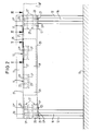
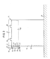
- Figures 1 and 3 are on the floor 13 of a kitchen in the side Distance between two support plates 12 vertically and parallel arranged to each other.
- a rectangular, horizontal one rests on the support plates 12 Worktop 11, which is laterally flush with the support plates 12 and connected to them preferably via longitudinal dovetail grooves 30 is like that is only indicated in Figure 3.
- the support plates 12 have vertical on their back Rail profiles in the form of dovetail grooves 16 on the Go through the floor 13 to the worktop 11 provided above. Between the support plates 12 is, for example, one under the worktop 11 in the longitudinal grooves 30 attached drawer body 28 shown, the rear upper attachment in the longitudinal grooves located below the worktop 11 Worktop 11 can be omitted. The relevant longitudinal groove 30 can completely eliminated in this area.
- the fasteners 17 according to FIGS. 3, 6 to 8 each have a flat piece 17 'and an angled one at 90 ° Angle piece 17 "so that there is a total of a 90 ° angle profile 2 and 6 to 8, the flat piece 17 'has near the angle piece 17 "three sliding block mounting holes provided at the same distance in the longitudinal direction 22 and at a greater distance from the contra-angle 17 "six rear wall mounting holes 23 on that Side from where fastening screws 21, 22 are screwed in are to enable the use of countersunk screws, which are flush with the surface of the flat piece 17 '.
- the length of the fastening elements 17 is such that it according to Figures 4, 6 and 7 by means of one of the sliding block mounting holes 22 passed fastening screw 20, which is screwed into the sliding block 19, such on the back of the Support plate 12 can be attached that the fastener 17 on at least one side of the support plate 12 protrudes so much from it, that there is a rear wall 18 applied from behind to the flat piece 17 ' from the front right through the interior of the furniture into the rear wall mounting holes 23 screwed screws attached can be.
- each flat piece 17 " only one sliding block 19 guided in the dovetail groove 16 is shown is, in principle, it is also possible to further improve the stability on each flat piece 17 'at a short distance two above one another Sliding block mounting holes 22 for two superimposed To provide sliding blocks 19.
- the thickness of the worktop is approx. 50 mm, the thickness of the rear wall approx. 20 mm.
- the lower angle fasteners are exactly mirror images the upper arranged so that there are the flat pieces 17 'from the elbow 17 "upwards.
- the lower fastening elements 17 are adjusted in height so that between the superimposed ones Elbows 17 "a rectangular rear wall 18 from the Length of the worktop 11 and the desired height inserted between them can be.
- a fastener 17 is formed or arranged that according to Figure 2 only to the opposite Support plate 12 facing side of the respective support plate 12 projects. Due to the multiple sliding block mounting holes 22 can different protrusions of the fasteners 17 realized become.
- drawer body 28 Due to the rear attachment of the drawer body 28 according to the Invention can be content with the drawer body 28 in front area only on both sides of the front dovetail groove 30 ( Figure 1) to set the worktop 11.
- the rear wall 18 is on both sides with the Worktop 11 or support plate 12 flush.
- the lowest back wall height should be approx. 30 cm.
- the rear wall 18 can, however, extend downward as far as that from optical or also for reasons of preventing the ingress of dirt or Moisture is desired.
- the distance and arrangement of the sliding block mounting holes 22 should be such that when three are arranged side by side Bores 22 according to Figures 6 to 8, the fastener 17 both in an arrangement protruding on both sides as well one of the two end sliding block mounting holes 26 attached can be that the fastener 17 is only either of the one or the other side of the support plate 12 extends away and with the other side is flush.
Landscapes
- Engineering & Computer Science (AREA)
- General Engineering & Computer Science (AREA)
- Mechanical Engineering (AREA)
- Furniture Connections (AREA)
- Finishing Walls (AREA)
- Mattresses And Other Support Structures For Chairs And Beds (AREA)
- Assembled Shelves (AREA)
Description
- Figur 1
- eine schematische Rückansicht eines erfindungsgemäßen Küchenmöbels mit einem unten an die Arbeitsplatte angebauten Schubladenkorpus, der die erfindungsgemäßen Befestigungselemente trägt, wobei der Anschaulichkeit halber die erfindungsgemäßen Befestigungselemente an den Tragplatten und die Rückwand fortgelassen sind,
- Figur 2
- eine Rückansicht analog Figur 1, wobei jedoch eine Rückwand mittels vier erfindungsgemäßen Befestigungselementen angebaut ist,
- Figur 3
- eine schematische Seitenansicht des Gegenstandes der Figur 2 von rechts,
- Figur 4
- eine schematische Schnittansicht nach Linie IV-IV in Figur 2,
- Figur 5
- eine schematische Schnittansicht nach Linie V-V in Figur 2,
- Figur 6
- eine etwas vergrößerte teilgeschnittene Ansicht analog Figur 4 ohne eingebaute Rückwand und mit noch nicht festgezogenem Gleitstein,
- Figur 7
- die gleiche Ansicht wie Figur 6, jedoch mit festgeschraubtem Gleitstein und
- Figur 8
- eine Ansicht des Befestigungselementes nach den Figuren 6, 7 von vorne, d.h. von der Seite her, von der die dahinter angebrachte Rückwand festgeschraubt wird.
- 11
- Arbeitsplatte
- 12
- Tragplatte
- 13
- Boden
- 14
- Vorderseite
- 15
- Rückseite
- 16
- Schienenprofil (Schwalbenschwanznut)
- 17
- Befestigungselement
- 17'
- Flachstück
- 17"
- Winkelstück
- 18
- Rückwand
- 18'
- Rückwand
- 19
- Gleitstein
- 20
- Befestigungsschraube
- 21
- Befestigungsschraube
- 22
- Gleitstein-Befestigungsbohrung
- 23
- Rückwand-Befestigungsbohrung
- 24
- Stirnseiten-Befestigungsbohrung
- 25
- Oberrand
- 26
- Unterrand
- 27
- Spalt
- 28
- Schubladenkorpus
- 29
- Gewindebohrung
- 30
- Schwalbenschwanznut
- 31
- Spalt
Claims (21)
- Möbel, insbesondere Küchenmöbel, mit wenigstens einer zumindest im wesentlichen horizontalen, insbesondere rechteckigen Platte (11), insbesondere Arbeitsplatte, mit einer Vorderseite (14) und einer Rückseite (15), welche über zumindest zwei seitliche, vorzugsweise parallel im Abstand zueinander und zumindest im wesentlichen vertikal angeordnete Tragplatten (12) auf einer Unterlage (13), insbesondere einem Boden, ruht, wobei die Tragplatten (12) an ihrer Rückseite ein parallel zur Längsseite der Rückseite, d.h. zumindest im wesentlichen vertikal verlaufendes Schienenprofil (16) aufweisen, an bzw. in dem wenigstens ein Befestigungselement (17) höhenverstellbar und insbesondere lösbar angebracht ist,
dadurch gekennzeichnet, dass das Befestigungselement (17) zumindest auf einer Seite über die Tragplatte (12) vorsteht und dass an dessen seitlich über die Tragplatte (12) vorstehendem Teil eine Rückwand (18) befestigt ist, wobei vorzugsweise an jeder Tragplatte (12) zwei Befestigungselemente (17) im Abstand übereinander vorgesehen sind und das obere Befestigungselement (17) vorzugsweise oben an die Platte (11) anstößt, während das untere Befestigungselement (17) am unteren Ende der Rückwand (18) angeordnet ist. - Möbel nach Anspruch 1,
dadurch gekennzeichnet, daß das Schienenprofil eine hinterschnittene Nut (16), insbesondere mit Schwalbenschwanzprofil ist, in dem für jedes Befestigungselement (17) zumindest ein Gleitstein (19) angeordnet ist, an dem das Befestigungselement (17) derart anschraubbar ist, daß es zunächst auf eine gewünschte Höhe eingestellt werden und dann durch Festziehen einer Befestigungsschraube (20) in dieser Höhe an der Tragplatte (12) festgelegt werden kann. - Möbel nach Anspruch 1 oder 2,
dadurch gekennzeichnet, daß das Befestigungselement (17) ein sich parallel zur Rückwand (18) erstreckendes, vorzugsweise senkrecht zur Tragplatte (12) längliches Flachstück (17') aufweist. - Möbel nach Anspruch 3,
dadurch gekennzeichnet, daß das Flachstück (17') flach an der hinteren Stirnseite der Tragplatte (12) anliegt. - Möbel nach Anspruch 3 oder 4,
dadurch gekennzeichnet, daß an dem Flachstück (17') von hinten die Rückwand (18) anliegt und das Flachstück (17') von vorne her z.B. durch Schrauben (21) mit der Rückwand (18) verbunden ist. - Möbel nach einem der Ansprüche 3 bis 5,
dadurch gekennzeichnet, daß an dem Flachstück (17') ein vorzugsweise um 90° nach hinten abgebogenes Winkelstück (17'') vorzugsweise gleicher Länge vorgesehen ist. - Möbel nach Anspruch 6,
dadurch gekennzeichnet, daß das Winkelstück (17") eine Tiefe entsprechend der Dicke der Rückwand (18) hat. - Möbel nach einem der vorhergehenden Ansprüche,
dadurch gekennzeichnet, daß für die Rückwand (18) an jeder Tragplatte (12) zwei im Abstand der Höhe der Rückwand (18) angeordnete Befestigungselemente (17) vorgesehen sind, und daß die Winkelstücke (17'') oben bzw. unten an der Rückwand (18) anliegen und die Flachstücke (17') der beiden Befestigungselemente (17) aufeinander zu weisen, wobei das obere Winkelstück (17'') bevorzugt von unten an der Platte (11) anliegt. - Möbel nach einem der vorhergehenden Ansprüche,
dadurch gekennzeichnet, daß das Befestigungselement (17) über die gesamte Breite an der Rückseite der Tragplatte (12) an dieser anliegt. - Möbel nach einem der vorhergehenden Ansprüche,
dadurch gekennzeichnet, daß das Befestigungselement nur von einer Seite oder von beiden Seiten der Tragplatte zur Befestigung einer Rückwand (18) bzw. zweier Rückwände (18, 18') vorsteht. - Möbel nach einem der Ansprüche 3 bis 10,
dadurch gekennzeichnet, daß das Flachstück (17') Gleitstein-Befestigungsbohrungen (22) und Rückwand-Befestigungsbohrungen (23) aufweist. - Möbel nach Anspruch 11,
dadurch gekennzeichnet, daß die Gleitstein-Befestigungsbohrungen (22) und die Rückwand-Befestigungsbohrungen (23) in zwei zumindest im wesentlichen horizontalen Reihen übereinander angeordnet sind, wobei die Gleitstein-Befestigungsbohrungen (22) näher am Winkelstück (17'') als die Rückwand-Befestigungsbohrungen (23) liegen. - Möbel nach Anspruch 11 oder 12,
dadurch gekennzeichnet, daß in Längsrichtung des Befestigungselementes (17) ein bis fünf, vorzugsweise zwei bis vier und insbesondere drei Gleitstein-Befestigungsbohrungen (22) vorzugsweise in gleichem Abstand angeordnet sind. - Möbel nach einem der Ansprüche 11 bis 13,
dadurch gekennzeichnet, daß vier bis zehn, insbesondere fünf bis acht und bevorzugt sechs Rückwand-Befestigungsbohrungen (23) vorzugsweise im gleichen Abstand in Längsrichtung des Befestigungselementes (17) vorgesehen sind. - Möbel nach einem der Ansprüche 6 bis 14,
dadurch gekennzeichnet, daß am Winkelstück (17") mindestens eine Stirnseiten-Befestigungsbohrung (24) vorgesehen ist. - Möbel nach Anspruch 15,
dadurch gekennzeichnet, daß ein bis fünf, vorzugsweise zwei bis vier und insbesondere drei Stirnseiten-Befestigungsbohrungen (24) vorzugsweise im gleichen Abstand in Längsrichtung des Winkelstückes (17'') vorgesehen sind. - Möbel nach einem der Ansprüche 6 bis 16,
dadurch gekennzeichnet, daß das Flachstück um einen Faktor 1,5 bis 2,5, insbesondere etwa 2 breiter als das Winkelstück (17'') ist. - Möbel nach einem der vorhergehenden Ansprüche,
dadurch gekennzeichnet, daß die Bohrungen (22, 23, 24) Senkbohrungen für Senkkopfschrauben sind, wobei die Senkungen der Gleitstein-Befestigungsbohrungen (22) auf der Rückseite, die Senkungen der Rückwand-Befestigungsbohrungen (23) auf der Vorderseite des Flachstücks (17') und die Senkungen der Stirnseiten-Befestigungsbohrungen (24) in der vom Flachstück (17') abgewandten Oberfläche des Winkelstücks (17") vorgesehen sind. - Möbel nach einem der vorhergehenden Ansprüche,
dadurch gekennzeichnet, daß der Oberrand (25) und/oder der Unterrand (26) der Rückwand (18) durchgehend horizontal verläuft. - Möbel nach Anspruch 19,
dadurch gekennzeichnet, daß in den durch das oberhalb der Rückwand (18) befindliche, von unten an der Platte (11) anliegende Winkelstück (17") bedingten Spalt (27) zwischen dem Oberrand (25) der Rückwand (18) und der Unterseite der Platte (11) zumindest an einer Stelle zwischen zwei benachbarten Befestigungselementen (17) ein Winkelstück (17'') eines weiteren, gleichartigen Befestigungselementes (17) eingreift, welches an der Rückseite eines Einbauteils (28) des Möbels befestigt ist. - Möbel nach Anspruch 20,
dadurch gekennzeichnet, daß an der Rückwand des Einbauteils, insbesondere eines Schubladenkorpus (28) ein bzw. in seitlichem Abstand zwei Flachstücke (17'') derart befestigt sind, daß beim Einsetzen des Einbauteils in das Möbel das bzw. die nach hinten vorstehende Winkelstücke (17") in den Spalt (27) greift bzw. greifen.
Applications Claiming Priority (2)
| Application Number | Priority Date | Filing Date | Title |
|---|---|---|---|
| DE19950550A DE19950550A1 (de) | 1999-10-20 | 1999-10-20 | Möbel |
| DE19950550 | 1999-10-20 |
Publications (2)
| Publication Number | Publication Date |
|---|---|
| EP1093733A1 EP1093733A1 (de) | 2001-04-25 |
| EP1093733B1 true EP1093733B1 (de) | 2004-10-06 |
Family
ID=7926298
Family Applications (1)
| Application Number | Title | Priority Date | Filing Date |
|---|---|---|---|
| EP00122710A Expired - Lifetime EP1093733B1 (de) | 1999-10-20 | 2000-10-18 | Möbel |
Country Status (3)
| Country | Link |
|---|---|
| EP (1) | EP1093733B1 (de) |
| AT (1) | ATE278342T1 (de) |
| DE (2) | DE19950550A1 (de) |
Family Cites Families (12)
| Publication number | Priority date | Publication date | Assignee | Title |
|---|---|---|---|---|
| US3595180A (en) * | 1969-02-10 | 1971-07-27 | Module Computer Corp | Adjustable height device for data processing equipment |
| FR2040927A5 (de) * | 1969-04-18 | 1971-01-22 | Roneo Cie | |
| CH583010A5 (de) * | 1973-11-12 | 1976-12-31 | Team Form Ag | |
| US3920298A (en) * | 1974-07-05 | 1975-11-18 | Camilo Muebles Inc | Convertible desk and secretarial return |
| DE2721077C3 (de) * | 1977-05-11 | 1980-02-07 | Hans Feierabend Gmbh, 3352 Einbeck | Kücheneinrichtung aus vorgefertigten Elementen |
| US4869564A (en) * | 1988-08-24 | 1989-09-26 | Nova Office Furniture, Inc. | Modular furniture |
| DE8815819U1 (de) * | 1988-12-21 | 1989-02-23 | Schroff Gmbh, 7541 Straubenhardt | Arbeitstisch, insbesondere für Bildschirmarbeitsplätze |
| DE9014882U1 (de) * | 1990-10-27 | 1991-01-10 | Egon Hillebrand Gmbh & Co, 5760 Arnsberg | Einrichtung für die Befestigung eines Tragarms an einer Tischplatte |
| US5531168A (en) * | 1994-07-21 | 1996-07-02 | Soho, Inc. | Adjustable table and shelf unit |
| ES2155686T3 (es) | 1996-04-26 | 2001-05-16 | Dreier Kuchen Gmbh & Co Kg | Mueble de cocina. |
| DE29612108U1 (de) * | 1996-07-11 | 1996-09-05 | Knürr-Mechanik für die Elektronik AG, 81829 München | Arbeitsmöbel |
| DE29720976U1 (de) * | 1997-11-26 | 1998-01-15 | Knürr-Mechanik für die Elektronik AG, 81829 München | Arbeitsmöbel |
-
1999
- 1999-10-20 DE DE19950550A patent/DE19950550A1/de not_active Withdrawn
-
2000
- 2000-10-18 AT AT00122710T patent/ATE278342T1/de not_active IP Right Cessation
- 2000-10-18 DE DE50008080T patent/DE50008080D1/de not_active Expired - Lifetime
- 2000-10-18 EP EP00122710A patent/EP1093733B1/de not_active Expired - Lifetime
Also Published As
| Publication number | Publication date |
|---|---|
| DE50008080D1 (de) | 2004-11-11 |
| DE19950550A1 (de) | 2001-04-26 |
| ATE278342T1 (de) | 2004-10-15 |
| EP1093733A1 (de) | 2001-04-25 |
Similar Documents
| Publication | Publication Date | Title |
|---|---|---|
| DE3632442C2 (de) | ||
| EP0200760B1 (de) | Profilstange zum festklemmen von platten, insbesondere von glasplatten, für schauvitrinen, verkaufstheken, messemobiliar od.dgl. | |
| DE19750427C1 (de) | Befestigungsvorrichtung | |
| DE3343066A1 (de) | Moebel mit hoehen- und/oder neigungsverstellbarer tischplatte | |
| DE4217501A1 (de) | Mobiler medizinischer Gerätetisch | |
| EP0645957A1 (de) | Gestellrahmen | |
| EP0948107A1 (de) | Vorrichtung zum Befestigen von Anbauelementen an einem Rahmenschenkel eines Schaltschrank-Rahmengestelles | |
| AT398516B (de) | Schubkastenauszug | |
| CH670555A5 (de) | ||
| EP0901207A1 (de) | Schaltschrank | |
| EP1093733B1 (de) | Möbel | |
| DE4443743A1 (de) | Vorrichtung zum Befestigen von Fassadenplatten | |
| EP3091133A1 (de) | Haltesystem für wandelemente | |
| AT399086B (de) | Verstellvorrichtung für schubladenblenden, insbesondere für küchenmöbelauszüge | |
| DE9102071U1 (de) | Befestigungsvorrichtung | |
| DE202022104870U1 (de) | Glasträgerelement mit montageseitig und fallseitig verschiebbaren Innenkeilen | |
| EP0133707A2 (de) | Schuhschrank mit höhenverstellbaren Fachböden | |
| DE102018008156B4 (de) | Vorrichtung zur Aufnahme einer Geländerplatte einer Geländeranordnung | |
| DE3412981C2 (de) | Vorrichtung zum Befestigen von Frontblenden an Möbelauszügen | |
| DE3533895C2 (de) | ||
| EP0055861A1 (de) | Befestigungselement für Möbel | |
| DE8716570U1 (de) | Trennwandverstellvorrichtung | |
| DE29509556U1 (de) | Schaltschrank mit Montageplatte | |
| DE9101567U1 (de) | Arbeitstisch | |
| EP0413396A1 (de) | Haushaltgerät, z.B. Geschirrspülmaschine |
Legal Events
| Date | Code | Title | Description |
|---|---|---|---|
| PUAI | Public reference made under article 153(3) epc to a published international application that has entered the european phase |
Free format text: ORIGINAL CODE: 0009012 |
|
| AK | Designated contracting states |
Kind code of ref document: A1 Designated state(s): AT BE CH CY DE DK ES FI FR GB GR IE IT LI LU MC NL PT SE |
|
| AX | Request for extension of the european patent |
Free format text: AL;LT;LV;MK;RO;SI |
|
| AKX | Designation fees paid | ||
| 17P | Request for examination filed |
Effective date: 20010830 |
|
| RBV | Designated contracting states (corrected) |
Designated state(s): AT BE CH CY DE DK ES FI FR GB GR IE IT LI LU MC NL PT SE |
|
| REG | Reference to a national code |
Ref country code: DE Ref legal event code: 8566 |
|
| 17Q | First examination report despatched |
Effective date: 20030120 |
|
| GRAP | Despatch of communication of intention to grant a patent |
Free format text: ORIGINAL CODE: EPIDOSNIGR1 |
|
| GRAS | Grant fee paid |
Free format text: ORIGINAL CODE: EPIDOSNIGR3 |
|
| GRAA | (expected) grant |
Free format text: ORIGINAL CODE: 0009210 |
|
| AK | Designated contracting states |
Kind code of ref document: B1 Designated state(s): AT BE CH CY DE DK ES FI FR GB GR IE IT LI LU MC NL PT SE |
|
| PG25 | Lapsed in a contracting state [announced via postgrant information from national office to epo] |
Ref country code: IT Free format text: LAPSE BECAUSE OF FAILURE TO SUBMIT A TRANSLATION OF THE DESCRIPTION OR TO PAY THE FEE WITHIN THE PRESCRIBED TIME-LIMIT;WARNING: LAPSES OF ITALIAN PATENTS WITH EFFECTIVE DATE BEFORE 2007 MAY HAVE OCCURRED AT ANY TIME BEFORE 2007. THE CORRECT EFFECTIVE DATE MAY BE DIFFERENT FROM THE ONE RECORDED. Effective date: 20041006 Ref country code: FI Free format text: LAPSE BECAUSE OF FAILURE TO SUBMIT A TRANSLATION OF THE DESCRIPTION OR TO PAY THE FEE WITHIN THE PRESCRIBED TIME-LIMIT Effective date: 20041006 Ref country code: FR Free format text: LAPSE BECAUSE OF NON-PAYMENT OF DUE FEES Effective date: 20041006 Ref country code: CY Free format text: LAPSE BECAUSE OF FAILURE TO SUBMIT A TRANSLATION OF THE DESCRIPTION OR TO PAY THE FEE WITHIN THE PRESCRIBED TIME-LIMIT Effective date: 20041006 Ref country code: IE Free format text: LAPSE BECAUSE OF FAILURE TO SUBMIT A TRANSLATION OF THE DESCRIPTION OR TO PAY THE FEE WITHIN THE PRESCRIBED TIME-LIMIT Effective date: 20041006 Ref country code: NL Free format text: LAPSE BECAUSE OF FAILURE TO SUBMIT A TRANSLATION OF THE DESCRIPTION OR TO PAY THE FEE WITHIN THE PRESCRIBED TIME-LIMIT Effective date: 20041006 Ref country code: GB Free format text: LAPSE BECAUSE OF FAILURE TO SUBMIT A TRANSLATION OF THE DESCRIPTION OR TO PAY THE FEE WITHIN THE PRESCRIBED TIME-LIMIT Effective date: 20041006 |
|
| REG | Reference to a national code |
Ref country code: GB Ref legal event code: FG4D Free format text: NOT ENGLISH |
|
| REG | Reference to a national code |
Ref country code: CH Ref legal event code: EP |
|
| PG25 | Lapsed in a contracting state [announced via postgrant information from national office to epo] |
Ref country code: AT Free format text: LAPSE BECAUSE OF NON-PAYMENT OF DUE FEES Effective date: 20041018 Ref country code: LU Free format text: LAPSE BECAUSE OF NON-PAYMENT OF DUE FEES Effective date: 20041018 |
|
| PG25 | Lapsed in a contracting state [announced via postgrant information from national office to epo] |
Ref country code: CH Free format text: LAPSE BECAUSE OF NON-PAYMENT OF DUE FEES Effective date: 20041031 Ref country code: BE Free format text: LAPSE BECAUSE OF NON-PAYMENT OF DUE FEES Effective date: 20041031 Ref country code: LI Free format text: LAPSE BECAUSE OF NON-PAYMENT OF DUE FEES Effective date: 20041031 Ref country code: MC Free format text: LAPSE BECAUSE OF NON-PAYMENT OF DUE FEES Effective date: 20041031 |
|
| REG | Reference to a national code |
Ref country code: IE Ref legal event code: FG4D Free format text: GERMAN |
|
| REF | Corresponds to: |
Ref document number: 50008080 Country of ref document: DE Date of ref document: 20041111 Kind code of ref document: P |
|
| PG25 | Lapsed in a contracting state [announced via postgrant information from national office to epo] |
Ref country code: DK Free format text: LAPSE BECAUSE OF FAILURE TO SUBMIT A TRANSLATION OF THE DESCRIPTION OR TO PAY THE FEE WITHIN THE PRESCRIBED TIME-LIMIT Effective date: 20050106 Ref country code: GR Free format text: LAPSE BECAUSE OF FAILURE TO SUBMIT A TRANSLATION OF THE DESCRIPTION OR TO PAY THE FEE WITHIN THE PRESCRIBED TIME-LIMIT Effective date: 20050106 Ref country code: SE Free format text: LAPSE BECAUSE OF FAILURE TO SUBMIT A TRANSLATION OF THE DESCRIPTION OR TO PAY THE FEE WITHIN THE PRESCRIBED TIME-LIMIT Effective date: 20050106 |
|
| PG25 | Lapsed in a contracting state [announced via postgrant information from national office to epo] |
Ref country code: ES Free format text: LAPSE BECAUSE OF FAILURE TO SUBMIT A TRANSLATION OF THE DESCRIPTION OR TO PAY THE FEE WITHIN THE PRESCRIBED TIME-LIMIT Effective date: 20050117 |
|
| NLV1 | Nl: lapsed or annulled due to failure to fulfill the requirements of art. 29p and 29m of the patents act | ||
| BERE | Be: lapsed |
Owner name: DREIER KUCHENSYSTEME G.M.B.H. & CO. KG Effective date: 20041031 |
|
| GBV | Gb: ep patent (uk) treated as always having been void in accordance with gb section 77(7)/1977 [no translation filed] |
Effective date: 20041006 |
|
| REG | Reference to a national code |
Ref country code: IE Ref legal event code: FD4D |
|
| REG | Reference to a national code |
Ref country code: CH Ref legal event code: PL |
|
| PLBE | No opposition filed within time limit |
Free format text: ORIGINAL CODE: 0009261 |
|
| STAA | Information on the status of an ep patent application or granted ep patent |
Free format text: STATUS: NO OPPOSITION FILED WITHIN TIME LIMIT |
|
| 26N | No opposition filed |
Effective date: 20050707 |
|
| EN | Fr: translation not filed | ||
| BERE | Be: lapsed |
Owner name: *DREIER KUCHENSYSTEME G.M.B.H. & CO. K.G. Effective date: 20041031 |
|
| PG25 | Lapsed in a contracting state [announced via postgrant information from national office to epo] |
Ref country code: PT Free format text: LAPSE BECAUSE OF NON-PAYMENT OF DUE FEES Effective date: 20050306 |
|
| PGFP | Annual fee paid to national office [announced via postgrant information from national office to epo] |
Ref country code: DE Payment date: 20101230 Year of fee payment: 11 |
|
| PG25 | Lapsed in a contracting state [announced via postgrant information from national office to epo] |
Ref country code: DE Free format text: LAPSE BECAUSE OF NON-PAYMENT OF DUE FEES Effective date: 20120501 |
|
| REG | Reference to a national code |
Ref country code: DE Ref legal event code: R119 Ref document number: 50008080 Country of ref document: DE Effective date: 20120501 |