EP1093763A2 - Knochenplatte - Google Patents
Knochenplatte Download PDFInfo
- Publication number
- EP1093763A2 EP1093763A2 EP00113452A EP00113452A EP1093763A2 EP 1093763 A2 EP1093763 A2 EP 1093763A2 EP 00113452 A EP00113452 A EP 00113452A EP 00113452 A EP00113452 A EP 00113452A EP 1093763 A2 EP1093763 A2 EP 1093763A2
- Authority
- EP
- European Patent Office
- Prior art keywords
- bone
- screw
- receiving opening
- bone plate
- receiving
- Prior art date
- Legal status (The legal status is an assumption and is not a legal conclusion. Google has not performed a legal analysis and makes no representation as to the accuracy of the status listed.)
- Granted
Links
- 210000000988 bone and bone Anatomy 0.000 title claims description 76
- 230000002401 inhibitory effect Effects 0.000 description 3
- 210000000115 thoracic cavity Anatomy 0.000 description 3
- 230000000694 effects Effects 0.000 description 1
- 230000005764 inhibitory process Effects 0.000 description 1
- 230000014759 maintenance of location Effects 0.000 description 1
- 238000000034 method Methods 0.000 description 1
- 238000005457 optimization Methods 0.000 description 1
- 238000007788 roughening Methods 0.000 description 1
Images
Classifications
-
- A—HUMAN NECESSITIES
- A61—MEDICAL OR VETERINARY SCIENCE; HYGIENE
- A61B—DIAGNOSIS; SURGERY; IDENTIFICATION
- A61B17/00—Surgical instruments, devices or methods
- A61B17/56—Surgical instruments or methods for treatment of bones or joints; Devices specially adapted therefor
- A61B17/58—Surgical instruments or methods for treatment of bones or joints; Devices specially adapted therefor for osteosynthesis, e.g. bone plates, screws or setting implements
- A61B17/68—Internal fixation devices, including fasteners and spinal fixators, even if a part thereof projects from the skin
- A61B17/70—Spinal positioners or stabilisers, e.g. stabilisers comprising fluid filler in an implant
- A61B17/7001—Screws or hooks combined with longitudinal elements which do not contact vertebrae
- A61B17/7044—Screws or hooks combined with longitudinal elements which do not contact vertebrae also having plates, staples or washers bearing on the vertebrae
-
- A—HUMAN NECESSITIES
- A61—MEDICAL OR VETERINARY SCIENCE; HYGIENE
- A61B—DIAGNOSIS; SURGERY; IDENTIFICATION
- A61B17/00—Surgical instruments, devices or methods
- A61B17/56—Surgical instruments or methods for treatment of bones or joints; Devices specially adapted therefor
- A61B17/58—Surgical instruments or methods for treatment of bones or joints; Devices specially adapted therefor for osteosynthesis, e.g. bone plates, screws or setting implements
- A61B17/68—Internal fixation devices, including fasteners and spinal fixators, even if a part thereof projects from the skin
- A61B17/70—Spinal positioners or stabilisers, e.g. stabilisers comprising fluid filler in an implant
- A61B17/7059—Cortical plates
-
- A—HUMAN NECESSITIES
- A61—MEDICAL OR VETERINARY SCIENCE; HYGIENE
- A61B—DIAGNOSIS; SURGERY; IDENTIFICATION
- A61B17/00—Surgical instruments, devices or methods
- A61B17/56—Surgical instruments or methods for treatment of bones or joints; Devices specially adapted therefor
- A61B17/58—Surgical instruments or methods for treatment of bones or joints; Devices specially adapted therefor for osteosynthesis, e.g. bone plates, screws or setting implements
- A61B17/68—Internal fixation devices, including fasteners and spinal fixators, even if a part thereof projects from the skin
- A61B17/80—Cortical plates, i.e. bone plates; Instruments for holding or positioning cortical plates, or for compressing bones attached to cortical plates
- A61B17/809—Cortical plates, i.e. bone plates; Instruments for holding or positioning cortical plates, or for compressing bones attached to cortical plates with bone-penetrating elements, e.g. blades or prongs
Definitions
- the invention relates to a bone plate for the Osteosynthesis with a plate - shaped body and a lid, the base body having a receiving opening to accommodate this e.g. on a vortex has fastening bone screw by the Screw head of the bone screw from the receiving opening is recorded.
- Bone plates are sufficient for osteosynthesis known. Such bone plates are e.g. on vertebrae attached to stabilize the vertebrae. For that be the individual bone plates over rods with each other connected, with the rods attached to the bone plates, be clamped in particular. To attach the Bone plates on the vertebrae become bone screws used that penetrate the bone plates and into the Vertebrae are screwed in. The bone plate is in the Usually held by the screw head.
- bone plates with a short overall length are prefer.
- the bone plates are said to be one have low overall height. These requirements will be but not met by bone plates, which by means of several bone screws on the bone, especially on Vertebrae are attached.
- the invention is therefore based on the object Provide bone plate that is thoracic with ease can be used.
- the bone plate according to the invention is, as usual, in hammered in the bone and using a bone screw attached. For the attachment, however, only one only bone screw used in this for this provided single receiving opening is inserted. The bone screw holds the Bone plate firmly attached to the bone. Since only one Bone screw is used, only one is required Receiving opening so that the overall length of the bone plate is significantly reduced. The thoracic use of this Bone plate does not cause any problems.
- a further training provides that the basic body with a receiving area for the fixing rod is provided and the receiving opening within this receiving area is provided. This eliminates additional areas in which the opening for the bone screw to be ordered. Because the receiving area for the fixing rod is provided in the base body anyway, can also in this the receiving opening for the screw head of the Bone screw.
- the receiving opening is located below the fixing rod.
- the fixing rod thus extends above the screw head of the bone screw. This allows an optimal introduction of force from the fixing rod exerted forces in the bones without the Bone plate is loaded with great moments that should also be supported.
- the fact that the receiving opening is provided symmetrically within the receiving area also contributes to this.
- the receiving opening is preferably on the center line of symmetry or in the vertical center plane of symmetry of the bone plate.
- the receiving opening is preferably designed as a countersink for a screw head of the bone screw designed as a countersunk head.
- the receiving opening is preferably dome-shaped, and the screw head of the bone screw is spherical. In this way, on the one hand, the base body of the bone plates is optimally held, and on the other hand, only a small overall height is required to accommodate the screw head.
- the receiving opening is at least over a portion of their facing the screw head Flat with a surface structure.
- a retention effect that is to say removal direction, is achieved for the screw head.
- the bone plate is thereby not only positively but also positively connected to the screw head and thus to the screw. Due to the form fit, the risk of the screw loosening, ie losing firm hold in the bone, is reduced. In addition, there is still a bond between the screw head and the bone plate, even if the bone changes its shape in the area of the abutment on the bone plate.
- the receiving opening is preferably circular. Such openings allow the screw head to be screwed in and fitted easily.
- the surface structure has only one Part of the circumference of the receiving opening is provided must be, the surface structure extends at one preferred embodiment over the entire Inner circumference of the receiving opening. This has the essential Advantage that the head of the bone screw is also over its entire outer circumference is fixed by is positively anchored in the receiving opening.
- a further training provides that the bone area of the receiving opening facing away Has surface structure.
- the almost vertical, i.e. less inclined area of the Provide the receiving opening with the surface structure, whereby the hold of the screw head is safer than in inclined area.
- the screw head In the area which is essentially is aligned perpendicular to the axis of the screw the screw head when screwing the screw in essentially parallel to and along the inner surface the receiving opening. Not until the end of the Screwing process the screw head lays down with its lower area on the inclined section of the dome-shaped receiving opening and holds thereby the bone plate is firmly attached to the bone.
- the surface structure preferably has an in Structural course directed circumferentially. To this An inhibition in the circumferential direction, i.e. in Direction of rotation of the screw achieved.
- Preferred embodiments provide that the Surface structure in the form of longitudinal grooves, one Gearing, a corrugation or the like. Is formed. It it is also conceivable that the surface structure is characterized by a Roughening of the surface is created.
- the longitudinal grooves or the toothing is designed in the form of a saw toothing.
- Each saw tooth of the saw toothing has a steep and a flat flank.
- the flat flank rises in the screwing-in direction of the bone screw. The bone screw can therefore be screwed in relatively easily and is secured against unscrewing by the steep flank of the saw tooth of the saw toothing.
- the screw head with a surface structure is provided, which supports the inhibitory effect.
- the screw head can also be used in the longitudinal direction extending grooves or the like. Provided. Also one Saw toothing is conceivable.
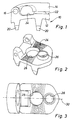
- FIG. 1 shows an overall designated 10 Bone plate, which has a base body 12 and a lid 14 has.
- the lid 14 is on a hinge 16 Base body 12 pivotally attached.
- the base body 12 points on its underside 18 facing the bone a total of four anchor wedges 20 (of which only two are visible). These anchor wedges 20 are in the bones hammered in until the bottom 18 on the Bone surface rests.
- the top 22 of the Base body 12 is with a receiving area 24 for one Fixing rod provided, which in this area is inserted.
- the attachment of the fixing rod on the Base body 12 in the receiving area 24 takes place through the Swing the cover 14 open, which by means of a Screw that has a threaded bore 26 ( Figures 2 and 3) is screwed to the base body 12.
- a receiving opening 28 is shown in FIGS. 2 and 3 recognizable which is a screw head of a bone screw records. Using this bone screw, the Bone plate 10 fixed on the bone. The receiving opening 28 is dome-shaped and lies in the Longitudinal median plane 30 of the bone plate 10. Also located the receiving opening 28 in the receiving area 24 for the Fixing rod. After inserting the bone screw into the Receiving opening 26 and attaching the bone plate 10 on The bone is removed using the bone screw Receiving opening 28 the screw head completely, so that no collision between the bone screw and the Fixing rod is created, i.e. the fixing rod in the Receiving area 24 inserted and held by the cover 14 can be. It is also conceivable that the receiving opening 28 has an offset to the longitudinal center plane 30.
- receiving openings 28 can be larger Diameter may be provided.
- the Offset of the receiving opening 28 to the longitudinal center plane 30 The length of the plate can also be shortened slightly.
Landscapes
- Health & Medical Sciences (AREA)
- Orthopedic Medicine & Surgery (AREA)
- Life Sciences & Earth Sciences (AREA)
- Neurology (AREA)
- Surgery (AREA)
- Heart & Thoracic Surgery (AREA)
- Engineering & Computer Science (AREA)
- Biomedical Technology (AREA)
- Nuclear Medicine, Radiotherapy & Molecular Imaging (AREA)
- Medical Informatics (AREA)
- Molecular Biology (AREA)
- Animal Behavior & Ethology (AREA)
- General Health & Medical Sciences (AREA)
- Public Health (AREA)
- Veterinary Medicine (AREA)
- Surgical Instruments (AREA)
- Polishing Bodies And Polishing Tools (AREA)
- Materials For Photolithography (AREA)
Abstract
Description
Die Aufnahmeöffnung liegt bevorzugt auf der Mittelsymmetrielinie bzw. in der vertikalen Mittelsymmetrieebene der Knochenplatte.
Mit Vorzug ist die Aufnahmeöffnung als Senkaufnahme für einen als Senkkopf ausgebildeten Schraubenkopf der Knochenschraube ausgebildet. Dabei ist die Aufnahmeöffnung bevorzugt kalottenförmig ausgeführt, und der Schraubenkopf der Knochenschraube ballig ausgebildet. Auf diese Weise wird zum einen der Grundkörper der Knochenplatten optimal gehalten zum anderen bedarf es für die Aufnahme des Schraubenkopfes nur einer geringen Bauhöhe.
Aufgrund des Formschlusses wird die Gefahr verringert, dass sich die Schraube lockert, d.h. den festen Halt im Knochen verliert. Außerdem besteht nach wie vor ein Verbund zwischen Schraubenkopf und Knochenplatte, auch wenn der Knochen im Bereich der Anlage an der Knochenplatte seine Form verändert.
Derartige Öffnungen erlauben ein problemloses Einschrauben und Anliegen des Schraubenkopfes.
Um eine Hemmwirkung in Aufschraubrichtung der Schraube zu erzielen, steigt die flache Flanke in Einschraubrichtung der Knochenschraube an. Die Knochenschraube kann daher relativ leicht eingeschraubt werden und wird von der steilen Flanke des Sägezahns der Sägeverzahnung gegen ein Ausschrauben gesichert.
- Figur 1
- eine Seitenansicht einer Knochenplatte mit in Schließstellung sich befindenden Deckel;
- Figur 2
- eine perspektivische Ansicht eines Grundkörpers der Knochenplatte mit abgenommenem Deckel; und
- Figur 3
- eine Draufsicht auf den Grundkörper bei geöffnetem Deckel.
Claims (6)
- Knochenplatte (10) für die Osteosynthese mit einem plattenförmigen Grundkörper (12) und einem Deckel (14), wobei der Grundkörper (12) eine Aufnahmeöffnung (28) zur Aufnahme einer diesen z.B. an einem Wirbel befestigenden Knochenschraube aufweist, indem der Schraubenkopf der Knochenschraube von der Aufnahmeöffnung (28) aufgenommen wird, dadurch gekennzeichnet, dass der Grundkörper (12) mit lediglich einer Aufnahmeöffnung (28) versehen ist.
- Knochenplatte nach Anspruch 1, dadurch gekennzeichnet, dass der Grundkörper (12) mit einem Aufnahmebereich (24) für einen Fixierstab versehen ist und die Aufnahmeöffnung (28) innerhalb dieses Aufnahmebereichs (24) vorgesehen ist.
- Knochenplatte nach Anspruch 2, dadurch gekennzeichnet, dass sich die Aufnahmeöffnung (28) unterhalb des Fixierstabes befindet.
- Knochenplatte nach Anspruch 2 oder 3, dadurch gekennzeichnet, dass die Aufnahmeöffnung (28) symmetrisch innerhalb des Aufnahmebereichs (24) vorgesehen ist.
- Knochenplatte nach einem der vorhergehenden Ansprüche, dadurch gekennzeichnet, dass die Aufnahmeöffnung (28) als Senkaufnahme für einen als Senkkopf ausgebildeten Schraubenkopf der Knochenschraube ausgebildet ist.
- Knochenplatte nach einem der vorhergehenden Ansprüche, dadurch gekennzeichnet, dass die Aufnahmeöffnung (28) kalottenförmig ausgebildet ist.
Applications Claiming Priority (2)
| Application Number | Priority Date | Filing Date | Title |
|---|---|---|---|
| DE19950252A DE19950252C2 (de) | 1999-10-18 | 1999-10-18 | Knochenplatte |
| DE19950252 | 1999-10-18 |
Publications (3)
| Publication Number | Publication Date |
|---|---|
| EP1093763A2 true EP1093763A2 (de) | 2001-04-25 |
| EP1093763A3 EP1093763A3 (de) | 2003-03-19 |
| EP1093763B1 EP1093763B1 (de) | 2007-03-07 |
Family
ID=7926112
Family Applications (1)
| Application Number | Title | Priority Date | Filing Date |
|---|---|---|---|
| EP00113452A Expired - Lifetime EP1093763B1 (de) | 1999-10-18 | 2000-06-24 | Knochenplatte |
Country Status (6)
| Country | Link |
|---|---|
| US (1) | US6656179B1 (de) |
| EP (1) | EP1093763B1 (de) |
| AT (1) | ATE355794T1 (de) |
| CA (1) | CA2318020C (de) |
| DE (2) | DE19950252C2 (de) |
| ES (1) | ES2283257T3 (de) |
Cited By (2)
| Publication number | Priority date | Publication date | Assignee | Title |
|---|---|---|---|---|
| FR2848408A1 (fr) * | 2002-12-17 | 2004-06-18 | Vitatech | Dispositif a plaque anterieure pour maintien du rachis |
| WO2004073534A1 (en) * | 2003-02-18 | 2004-09-02 | Sdgi Holdings Inc. | Spinal plate having an integral rod connector portion |
Families Citing this family (126)
| Publication number | Priority date | Publication date | Assignee | Title |
|---|---|---|---|---|
| US7833250B2 (en) | 2004-11-10 | 2010-11-16 | Jackson Roger P | Polyaxial bone screw with helically wound capture connection |
| US6726689B2 (en) | 2002-09-06 | 2004-04-27 | Roger P. Jackson | Helical interlocking mating guide and advancement structure |
| US8377100B2 (en) | 2000-12-08 | 2013-02-19 | Roger P. Jackson | Closure for open-headed medical implant |
| US6872210B2 (en) * | 2001-02-23 | 2005-03-29 | James P. Hearn | Sternum fixation device |
| US7862587B2 (en) | 2004-02-27 | 2011-01-04 | Jackson Roger P | Dynamic stabilization assemblies, tool set and method |
| US8292926B2 (en) | 2005-09-30 | 2012-10-23 | Jackson Roger P | Dynamic stabilization connecting member with elastic core and outer sleeve |
| US10729469B2 (en) | 2006-01-09 | 2020-08-04 | Roger P. Jackson | Flexible spinal stabilization assembly with spacer having off-axis core member |
| US8353932B2 (en) | 2005-09-30 | 2013-01-15 | Jackson Roger P | Polyaxial bone anchor assembly with one-piece closure, pressure insert and plastic elongate member |
| US10258382B2 (en) | 2007-01-18 | 2019-04-16 | Roger P. Jackson | Rod-cord dynamic connection assemblies with slidable bone anchor attachment members along the cord |
| FR2842724B1 (fr) | 2002-07-23 | 2005-05-27 | Spine Next Sa | Systeme de fixation vertebrale |
| US7179260B2 (en) | 2003-09-29 | 2007-02-20 | Smith & Nephew, Inc. | Bone plates and bone plate assemblies |
| US8257402B2 (en) | 2002-09-06 | 2012-09-04 | Jackson Roger P | Closure for rod receiving orthopedic implant having left handed thread removal |
| US8282673B2 (en) | 2002-09-06 | 2012-10-09 | Jackson Roger P | Anti-splay medical implant closure with multi-surface removal aperture |
| US8876868B2 (en) | 2002-09-06 | 2014-11-04 | Roger P. Jackson | Helical guide and advancement flange with radially loaded lip |
| WO2006052796A2 (en) | 2004-11-10 | 2006-05-18 | Jackson Roger P | Helical guide and advancement flange with break-off extensions |
| JP2004097707A (ja) * | 2002-09-12 | 2004-04-02 | Showa Ika Kohgyo Co Ltd | 脊柱固定システム用の椎体プレート |
| US7621918B2 (en) | 2004-11-23 | 2009-11-24 | Jackson Roger P | Spinal fixation tool set and method |
| US6716214B1 (en) | 2003-06-18 | 2004-04-06 | Roger P. Jackson | Polyaxial bone screw with spline capture connection |
| US8540753B2 (en) | 2003-04-09 | 2013-09-24 | Roger P. Jackson | Polyaxial bone screw with uploaded threaded shank and method of assembly and use |
| US20170020683A1 (en) | 2003-04-21 | 2017-01-26 | Rsb Spine Llc | Bone plate stabilization system and method for its use |
| US8613772B2 (en) * | 2003-04-21 | 2013-12-24 | Rsb Spine Llc | Lateral mount implant device |
| US7985255B2 (en) * | 2003-04-21 | 2011-07-26 | Rsb Spine Llc | Implant subsidence control |
| US8100976B2 (en) * | 2003-04-21 | 2012-01-24 | Rsb Spine Llc | Implant subsidence control |
| US9278009B2 (en) * | 2003-04-21 | 2016-03-08 | Rsb Spine Llc | Spine implants |
| US7377923B2 (en) | 2003-05-22 | 2008-05-27 | Alphatec Spine, Inc. | Variable angle spinal screw assembly |
| US8257398B2 (en) * | 2003-06-18 | 2012-09-04 | Jackson Roger P | Polyaxial bone screw with cam capture |
| US8936623B2 (en) | 2003-06-18 | 2015-01-20 | Roger P. Jackson | Polyaxial bone screw assembly |
| US7776067B2 (en) | 2005-05-27 | 2010-08-17 | Jackson Roger P | Polyaxial bone screw with shank articulation pressure insert and method |
| US7967850B2 (en) | 2003-06-18 | 2011-06-28 | Jackson Roger P | Polyaxial bone anchor with helical capture connection, insert and dual locking assembly |
| US8137386B2 (en) | 2003-08-28 | 2012-03-20 | Jackson Roger P | Polyaxial bone screw apparatus |
| US8814911B2 (en) | 2003-06-18 | 2014-08-26 | Roger P. Jackson | Polyaxial bone screw with cam connection and lock and release insert |
| US8377102B2 (en) | 2003-06-18 | 2013-02-19 | Roger P. Jackson | Polyaxial bone anchor with spline capture connection and lower pressure insert |
| US8366753B2 (en) | 2003-06-18 | 2013-02-05 | Jackson Roger P | Polyaxial bone screw assembly with fixed retaining structure |
| US8092500B2 (en) | 2007-05-01 | 2012-01-10 | Jackson Roger P | Dynamic stabilization connecting member with floating core, compression spacer and over-mold |
| US8398682B2 (en) | 2003-06-18 | 2013-03-19 | Roger P. Jackson | Polyaxial bone screw assembly |
| US7766915B2 (en) | 2004-02-27 | 2010-08-03 | Jackson Roger P | Dynamic fixation assemblies with inner core and outer coil-like member |
| US11419642B2 (en) | 2003-12-16 | 2022-08-23 | Medos International Sarl | Percutaneous access devices and bone anchor assemblies |
| US7527638B2 (en) | 2003-12-16 | 2009-05-05 | Depuy Spine, Inc. | Methods and devices for minimally invasive spinal fixation element placement |
| US7179261B2 (en) | 2003-12-16 | 2007-02-20 | Depuy Spine, Inc. | Percutaneous access devices and bone anchor assemblies |
| US7160300B2 (en) | 2004-02-27 | 2007-01-09 | Jackson Roger P | Orthopedic implant rod reduction tool set and method |
| US8152810B2 (en) | 2004-11-23 | 2012-04-10 | Jackson Roger P | Spinal fixation tool set and method |
| JP2007525274A (ja) | 2004-02-27 | 2007-09-06 | ロジャー・ピー・ジャクソン | 整形外科インプラントロッド整復器具セット及び方法 |
| US11241261B2 (en) | 2005-09-30 | 2022-02-08 | Roger P Jackson | Apparatus and method for soft spinal stabilization using a tensionable cord and releasable end structure |
| US7651502B2 (en) | 2004-09-24 | 2010-01-26 | Jackson Roger P | Spinal fixation tool set and method for rod reduction and fastener insertion |
| US8926672B2 (en) | 2004-11-10 | 2015-01-06 | Roger P. Jackson | Splay control closure for open bone anchor |
| US9168069B2 (en) | 2009-06-15 | 2015-10-27 | Roger P. Jackson | Polyaxial bone anchor with pop-on shank and winged insert with lower skirt for engaging a friction fit retainer |
| WO2006057837A1 (en) | 2004-11-23 | 2006-06-01 | Jackson Roger P | Spinal fixation tool attachment structure |
| US9216041B2 (en) | 2009-06-15 | 2015-12-22 | Roger P. Jackson | Spinal connecting members with tensioned cords and rigid sleeves for engaging compression inserts |
| US7875065B2 (en) | 2004-11-23 | 2011-01-25 | Jackson Roger P | Polyaxial bone screw with multi-part shank retainer and pressure insert |
| US9980753B2 (en) | 2009-06-15 | 2018-05-29 | Roger P Jackson | pivotal anchor with snap-in-place insert having rotation blocking extensions |
| US8308782B2 (en) | 2004-11-23 | 2012-11-13 | Jackson Roger P | Bone anchors with longitudinal connecting member engaging inserts and closures for fixation and optional angulation |
| US8444681B2 (en) | 2009-06-15 | 2013-05-21 | Roger P. Jackson | Polyaxial bone anchor with pop-on shank, friction fit retainer and winged insert |
| ATE524121T1 (de) | 2004-11-24 | 2011-09-15 | Abdou Samy | Vorrichtungen zur platzierung eines orthopädischen intervertebralen implantats |
| US7901437B2 (en) | 2007-01-26 | 2011-03-08 | Jackson Roger P | Dynamic stabilization member with molded connection |
| US10076361B2 (en) | 2005-02-22 | 2018-09-18 | Roger P. Jackson | Polyaxial bone screw with spherical capture, compression and alignment and retention structures |
| US20060259141A1 (en) * | 2005-05-13 | 2006-11-16 | Walter Lorenz Surgical, Inc. | Pectus bar stabilizer |
| FR2889437B1 (fr) * | 2005-08-02 | 2008-04-18 | Euro Sa | Implant rachidien a moyen de blocage pivotant pour une tige de liaison |
| FR2890850B1 (fr) | 2005-09-20 | 2009-04-17 | Abbott Spine Sa | Systeme de fixation vertebrale |
| FR2890851B1 (fr) * | 2005-09-21 | 2008-06-20 | Abbott Spine Sa | Ancillaire de mise en tension d'un lien souple. |
| KR20080068674A (ko) * | 2005-09-30 | 2008-07-23 | 패러다임 스파인, 엘엘씨 | 힌지식 다축성 스크류와 그 사용 방법 |
| US8105368B2 (en) | 2005-09-30 | 2012-01-31 | Jackson Roger P | Dynamic stabilization connecting member with slitted core and outer sleeve |
| US20070118130A1 (en) * | 2005-11-22 | 2007-05-24 | Depuy Spine, Inc. | Implant fixation methods and apparatus |
| US20070118128A1 (en) * | 2005-11-22 | 2007-05-24 | Depuy Spine, Inc. | Implant fixation methods and apparatus |
| US20070118127A1 (en) * | 2005-11-22 | 2007-05-24 | Depuy Spine, Inc. | Implant fixation methods and apparatus |
| US20070118129A1 (en) * | 2005-11-22 | 2007-05-24 | Depuy Spine, Inc. | Implant fixation methods and apparatus |
| US7704271B2 (en) | 2005-12-19 | 2010-04-27 | Abdou M Samy | Devices and methods for inter-vertebral orthopedic device placement |
| US7731735B2 (en) * | 2006-04-28 | 2010-06-08 | Warsaw Orthopedic, Inc. | Open axle surgical implant |
| WO2007146541A2 (en) * | 2006-06-09 | 2007-12-21 | Gyrus Productions | Method of performing a decompressive craniectomy |
| EP2047813A1 (de) | 2007-10-11 | 2009-04-15 | Abbott Spine | Knochenbefestigungssystem und Verfahren zu dessen Verwendung |
| JP2010512178A (ja) | 2006-12-08 | 2010-04-22 | ロジャー・ピー・ジャクソン | 動的脊椎インプラントのためのツールシステム |
| US8475498B2 (en) | 2007-01-18 | 2013-07-02 | Roger P. Jackson | Dynamic stabilization connecting member with cord connection |
| US8366745B2 (en) | 2007-05-01 | 2013-02-05 | Jackson Roger P | Dynamic stabilization assembly having pre-compressed spacers with differential displacements |
| US8012177B2 (en) | 2007-02-12 | 2011-09-06 | Jackson Roger P | Dynamic stabilization assembly with frusto-conical connection |
| US10383660B2 (en) | 2007-05-01 | 2019-08-20 | Roger P. Jackson | Soft stabilization assemblies with pretensioned cords |
| US7942910B2 (en) | 2007-05-16 | 2011-05-17 | Ortho Innovations, Llc | Polyaxial bone screw |
| US7942911B2 (en) | 2007-05-16 | 2011-05-17 | Ortho Innovations, Llc | Polyaxial bone screw |
| US8197518B2 (en) | 2007-05-16 | 2012-06-12 | Ortho Innovations, Llc | Thread-thru polyaxial pedicle screw system |
| US7951173B2 (en) | 2007-05-16 | 2011-05-31 | Ortho Innovations, Llc | Pedicle screw implant system |
| US7942909B2 (en) | 2009-08-13 | 2011-05-17 | Ortho Innovations, Llc | Thread-thru polyaxial pedicle screw system |
| US7947065B2 (en) | 2008-11-14 | 2011-05-24 | Ortho Innovations, Llc | Locking polyaxial ball and socket fastener |
| EP2160158A4 (de) | 2007-05-31 | 2013-06-26 | Roger P Jackson | Dynamisches stabilisationsverbindungselement mit vorgespanntem festen kern |
| US8128635B2 (en) * | 2007-10-23 | 2012-03-06 | Zimmer Spine S.A.S. | Bone fixation tensioning tool and method |
| ATE536824T1 (de) * | 2007-10-23 | 2011-12-15 | Zimmer Spine | Befestigungsvorrichtungen und stabilisierungssysteme mit diesen befestigungsvorrichtungen |
| US8911477B2 (en) | 2007-10-23 | 2014-12-16 | Roger P. Jackson | Dynamic stabilization member with end plate support and cable core extension |
| US20090248077A1 (en) * | 2008-03-31 | 2009-10-01 | Derrick William Johns | Hybrid dynamic stabilization |
| US8414584B2 (en) | 2008-07-09 | 2013-04-09 | Icon Orthopaedic Concepts, Llc | Ankle arthrodesis nail and outrigger assembly |
| US8328807B2 (en) | 2008-07-09 | 2012-12-11 | Icon Orthopaedic Concepts, Llc | Ankle arthrodesis nail and outrigger assembly |
| WO2010147639A1 (en) | 2008-08-01 | 2010-12-23 | Jackson Roger P | Longitudinal connecting member with sleeved tensioned cords |
| US8075603B2 (en) | 2008-11-14 | 2011-12-13 | Ortho Innovations, Llc | Locking polyaxial ball and socket fastener |
| WO2013043218A1 (en) | 2009-06-15 | 2013-03-28 | Jackson Roger P | Polyaxial bone anchor with pop-on shank and winged insert with friction fit compressive collet |
| US11229457B2 (en) | 2009-06-15 | 2022-01-25 | Roger P. Jackson | Pivotal bone anchor assembly with insert tool deployment |
| EP2753252A1 (de) | 2009-06-15 | 2014-07-16 | Jackson, Roger P. | Polyaxialer knochenanker mit pop-on-schaft und presssitzfixierung mit niedrigprofilkantensperre |
| US8998959B2 (en) | 2009-06-15 | 2015-04-07 | Roger P Jackson | Polyaxial bone anchors with pop-on shank, fully constrained friction fit retainer and lock and release insert |
| US9668771B2 (en) | 2009-06-15 | 2017-06-06 | Roger P Jackson | Soft stabilization assemblies with off-set connector |
| AU2010303934B2 (en) | 2009-10-05 | 2014-03-27 | Roger P. Jackson | Polyaxial bone anchor with non-pivotable retainer and pop-on shank, some with friction fit |
| US8764806B2 (en) | 2009-12-07 | 2014-07-01 | Samy Abdou | Devices and methods for minimally invasive spinal stabilization and instrumentation |
| US12383311B2 (en) | 2010-05-14 | 2025-08-12 | Roger P. Jackson | Pivotal bone anchor assembly and method for use thereof |
| WO2012030712A1 (en) | 2010-08-30 | 2012-03-08 | Zimmer Spine, Inc. | Polyaxial pedicle screw |
| JP2013540468A (ja) | 2010-09-08 | 2013-11-07 | ロジャー・ピー・ジャクソン | 弾性部および非弾性部を有する動的固定化部材 |
| JP2013545527A (ja) | 2010-11-02 | 2013-12-26 | ロジャー・ピー・ジャクソン | ポップオン式シャンクと枢動可能な保持部とを有する多軸の骨アンカー |
| US8992579B1 (en) * | 2011-03-08 | 2015-03-31 | Nuvasive, Inc. | Lateral fixation constructs and related methods |
| WO2012128825A1 (en) | 2011-03-24 | 2012-09-27 | Jackson Roger P | Polyaxial bone anchor with compound articulation and pop-on shank |
| US8845728B1 (en) | 2011-09-23 | 2014-09-30 | Samy Abdou | Spinal fixation devices and methods of use |
| US8911479B2 (en) | 2012-01-10 | 2014-12-16 | Roger P. Jackson | Multi-start closures for open implants |
| US20130226240A1 (en) | 2012-02-22 | 2013-08-29 | Samy Abdou | Spinous process fixation devices and methods of use |
| US9060815B1 (en) | 2012-03-08 | 2015-06-23 | Nuvasive, Inc. | Systems and methods for performing spine surgery |
| US9198767B2 (en) | 2012-08-28 | 2015-12-01 | Samy Abdou | Devices and methods for spinal stabilization and instrumentation |
| US9320617B2 (en) | 2012-10-22 | 2016-04-26 | Cogent Spine, LLC | Devices and methods for spinal stabilization and instrumentation |
| US8911478B2 (en) | 2012-11-21 | 2014-12-16 | Roger P. Jackson | Splay control closure for open bone anchor |
| US10058354B2 (en) | 2013-01-28 | 2018-08-28 | Roger P. Jackson | Pivotal bone anchor assembly with frictional shank head seating surfaces |
| US8852239B2 (en) | 2013-02-15 | 2014-10-07 | Roger P Jackson | Sagittal angle screw with integral shank and receiver |
| US9453526B2 (en) | 2013-04-30 | 2016-09-27 | Degen Medical, Inc. | Bottom-loading anchor assembly |
| US9517089B1 (en) | 2013-10-08 | 2016-12-13 | Nuvasive, Inc. | Bone anchor with offset rod connector |
| US9566092B2 (en) | 2013-10-29 | 2017-02-14 | Roger P. Jackson | Cervical bone anchor with collet retainer and outer locking sleeve |
| US9743968B2 (en) | 2013-11-14 | 2017-08-29 | Zimmer Biomet CMF and Thoracic, LLC | Locking mechanism for pectus bar |
| US9717533B2 (en) | 2013-12-12 | 2017-08-01 | Roger P. Jackson | Bone anchor closure pivot-splay control flange form guide and advancement structure |
| US9451993B2 (en) | 2014-01-09 | 2016-09-27 | Roger P. Jackson | Bi-radial pop-on cervical bone anchor |
| US10064658B2 (en) | 2014-06-04 | 2018-09-04 | Roger P. Jackson | Polyaxial bone anchor with insert guides |
| US9597119B2 (en) | 2014-06-04 | 2017-03-21 | Roger P. Jackson | Polyaxial bone anchor with polymer sleeve |
| JP2017525548A (ja) | 2014-08-28 | 2017-09-07 | ネクストレミティ ソルーションズ インコーポレイテッドNextremity Solutions, Inc. | 骨固定装置および方法 |
| US10857003B1 (en) | 2015-10-14 | 2020-12-08 | Samy Abdou | Devices and methods for vertebral stabilization |
| US10973648B1 (en) | 2016-10-25 | 2021-04-13 | Samy Abdou | Devices and methods for vertebral bone realignment |
| US10744000B1 (en) | 2016-10-25 | 2020-08-18 | Samy Abdou | Devices and methods for vertebral bone realignment |
| AU2018217805B2 (en) | 2017-02-10 | 2020-03-12 | Zimmer Biomet CMF and Thoracic, LLC | Pectus bar and stabilizer devices and methods |
| US10617455B2 (en) | 2017-03-08 | 2020-04-14 | Zimmer Biomet CMF and Thoracic, LLC | Pectus bar support devices and methods |
| US11179248B2 (en) | 2018-10-02 | 2021-11-23 | Samy Abdou | Devices and methods for spinal implantation |
Family Cites Families (11)
| Publication number | Priority date | Publication date | Assignee | Title |
|---|---|---|---|---|
| US5344422A (en) * | 1989-10-30 | 1994-09-06 | Synthes (U.S.A.) | Pedicular screw clamp |
| EP0699056B1 (de) * | 1993-05-18 | 1997-01-29 | Schäfer micomed GmbH | Knochenchirurgische haltevorrichtung |
| DE4414782C2 (de) * | 1994-04-28 | 2000-03-09 | Schaefer Micomed Gmbh | Knochenchirurgische Haltevorrichtung |
| US5662652A (en) * | 1994-04-28 | 1997-09-02 | Schafer Micomed Gmbh | Bone surgery holding apparatus |
| DE4433360C2 (de) * | 1994-07-19 | 1996-12-12 | Schaefer Micomed Gmbh | Knochenchirurgische Haltevorrichtung |
| DE19509331C2 (de) * | 1995-03-15 | 1998-01-15 | Juergen Harms | Element zur Halswirbelstabilisierung |
| US5669911A (en) * | 1995-04-13 | 1997-09-23 | Fastenetix, L.L.C. | Polyaxial pedicle screw |
| US5882350A (en) * | 1995-04-13 | 1999-03-16 | Fastenetix, Llc | Polyaxial pedicle screw having a threaded and tapered compression locking mechanism |
| US5925047A (en) * | 1998-10-19 | 1999-07-20 | Third Millennium Engineering, Llc | Coupled rod, anterior vertebral body screw, and staple assembly |
| US5947969A (en) * | 1998-10-19 | 1999-09-07 | Third Millennium Engineering, Llc | Rotatable locking vertebral body screw, staple and rod assembly |
| US6302888B1 (en) * | 1999-03-19 | 2001-10-16 | Interpore Cross International | Locking dovetail and self-limiting set screw assembly for a spinal stabilization member |
-
1999
- 1999-10-18 DE DE19950252A patent/DE19950252C2/de not_active Expired - Fee Related
-
2000
- 2000-06-24 DE DE50014130T patent/DE50014130D1/de not_active Expired - Lifetime
- 2000-06-24 ES ES00113452T patent/ES2283257T3/es not_active Expired - Lifetime
- 2000-06-24 EP EP00113452A patent/EP1093763B1/de not_active Expired - Lifetime
- 2000-06-24 AT AT00113452T patent/ATE355794T1/de not_active IP Right Cessation
- 2000-09-11 CA CA002318020A patent/CA2318020C/en not_active Expired - Fee Related
- 2000-10-18 US US09/690,765 patent/US6656179B1/en not_active Expired - Fee Related
Non-Patent Citations (1)
| Title |
|---|
| None |
Cited By (4)
| Publication number | Priority date | Publication date | Assignee | Title |
|---|---|---|---|---|
| FR2848408A1 (fr) * | 2002-12-17 | 2004-06-18 | Vitatech | Dispositif a plaque anterieure pour maintien du rachis |
| WO2004064654A1 (fr) * | 2002-12-17 | 2004-08-05 | Vitatech | Dispositif a plaque anterieure pour maintien du rachis |
| US7455684B2 (en) | 2002-12-17 | 2008-11-25 | Vitatech | Device comprising anterior plate for vertebral column support |
| WO2004073534A1 (en) * | 2003-02-18 | 2004-09-02 | Sdgi Holdings Inc. | Spinal plate having an integral rod connector portion |
Also Published As
| Publication number | Publication date |
|---|---|
| DE19950252C2 (de) | 2002-01-17 |
| EP1093763A3 (de) | 2003-03-19 |
| EP1093763B1 (de) | 2007-03-07 |
| ES2283257T3 (es) | 2007-11-01 |
| US6656179B1 (en) | 2003-12-02 |
| CA2318020C (en) | 2008-05-13 |
| DE19950252A1 (de) | 2001-06-07 |
| CA2318020A1 (en) | 2001-04-18 |
| DE50014130D1 (de) | 2007-04-19 |
| ATE355794T1 (de) | 2007-03-15 |
Similar Documents
| Publication | Publication Date | Title |
|---|---|---|
| DE19950252C2 (de) | Knochenplatte | |
| EP1093762B1 (de) | Knochenplatte | |
| DE4302397C2 (de) | Künstlicher Wirbelabstandshalter | |
| EP0760632B1 (de) | Knochenplatte | |
| DE69624672T2 (de) | Wirbelsäulenimplantat | |
| DE4115959C1 (de) | ||
| DE69404216T2 (de) | Wirbelfixationsvorrichtung zum Halten der Wirbelsäule | |
| DE19726754C2 (de) | Implantat zur Fixierung von Knochenteilen und Werkzeug für dieses Implantat | |
| DE69406869T2 (de) | Schraube für Lumbosakrale Fixationsvorrichtung | |
| AT389992B (de) | Vorrichtung zur externen fixierung von knochenfragmenten | |
| DE60024871T2 (de) | Pedikelschrauben mit schrägen ausnehmungen für stützstäbe | |
| EP0633750B1 (de) | Gegenspannscheibe für die plattenosteosynthese | |
| DE60034528T2 (de) | Vorder- und transpediculares Fixiersystem zum Befestigen der Wirbelsäule | |
| EP2457541A1 (de) | Zwischenwirbelimplantat | |
| EP2515779A1 (de) | Knochenplattensystem für die osteosynthese | |
| WO2004026159A1 (de) | Halswirbelplatte | |
| WO2001019268A1 (de) | Fixationssystem für knochen | |
| DE9321544U1 (de) | Osteosynthetische Platte | |
| DE29823952U1 (de) | Implantat zur Stabilisierung einer Fraktur | |
| CH676322A5 (de) | ||
| DE102005004841B4 (de) | Osteosyntheseplatte mit einer Vielzahl von Bohrungen zur Aufnahme von Knochenschrauben | |
| WO2008075160A1 (de) | Plattenimplantat, insbesondere für die anwendung an einer wirbelsäule, mit einem schraubenverschlusss stem | |
| DE102009060396A1 (de) | Knochenplatte mit Vorrichtung zur winkelstabilen Schraubenfixation und Schrauben hierfür | |
| DE202009012270U1 (de) | Knochenplattenverschraubung | |
| DE3725111C2 (de) |
Legal Events
| Date | Code | Title | Description |
|---|---|---|---|
| PUAI | Public reference made under article 153(3) epc to a published international application that has entered the european phase |
Free format text: ORIGINAL CODE: 0009012 |
|
| AK | Designated contracting states |
Kind code of ref document: A2 Designated state(s): AT BE CH CY DE DK ES FI FR GB GR IE IT LI LU MC NL PT SE |
|
| AX | Request for extension of the european patent |
Free format text: AL;LT;LV;MK;RO;SI |
|
| PUAL | Search report despatched |
Free format text: ORIGINAL CODE: 0009013 |
|
| AK | Designated contracting states |
Kind code of ref document: A3 Designated state(s): AT BE CH CY DE DK ES FI FR GB GR IE IT LI LU MC NL PT SE |
|
| AX | Request for extension of the european patent |
Extension state: AL LT LV MK RO SI |
|
| 17P | Request for examination filed |
Effective date: 20030228 |
|
| AKX | Designation fees paid |
Designated state(s): AT BE CH CY DE DK ES FI FR GB GR IE IT LI LU MC NL PT SE |
|
| RAP1 | Party data changed (applicant data changed or rights of an application transferred) |
Owner name: DEPUY SPINE SAERL |
|
| 17Q | First examination report despatched |
Effective date: 20050208 |
|
| GRAP | Despatch of communication of intention to grant a patent |
Free format text: ORIGINAL CODE: EPIDOSNIGR1 |
|
| GRAS | Grant fee paid |
Free format text: ORIGINAL CODE: EPIDOSNIGR3 |
|
| GRAA | (expected) grant |
Free format text: ORIGINAL CODE: 0009210 |
|
| AK | Designated contracting states |
Kind code of ref document: B1 Designated state(s): AT BE CH CY DE DK ES FI FR GB GR IE IT LI LU MC NL PT SE |
|
| PG25 | Lapsed in a contracting state [announced via postgrant information from national office to epo] |
Ref country code: NL Free format text: LAPSE BECAUSE OF FAILURE TO SUBMIT A TRANSLATION OF THE DESCRIPTION OR TO PAY THE FEE WITHIN THE PRESCRIBED TIME-LIMIT Effective date: 20070307 Ref country code: FI Free format text: LAPSE BECAUSE OF FAILURE TO SUBMIT A TRANSLATION OF THE DESCRIPTION OR TO PAY THE FEE WITHIN THE PRESCRIBED TIME-LIMIT Effective date: 20070307 Ref country code: IE Free format text: LAPSE BECAUSE OF FAILURE TO SUBMIT A TRANSLATION OF THE DESCRIPTION OR TO PAY THE FEE WITHIN THE PRESCRIBED TIME-LIMIT Effective date: 20070307 |
|
| REG | Reference to a national code |
Ref country code: GB Ref legal event code: FG4D Free format text: NOT ENGLISH |
|
| GBT | Gb: translation of ep patent filed (gb section 77(6)(a)/1977) |
Effective date: 20070307 |
|
| REG | Reference to a national code |
Ref country code: CH Ref legal event code: EP |
|
| REF | Corresponds to: |
Ref document number: 50014130 Country of ref document: DE Date of ref document: 20070419 Kind code of ref document: P |
|
| REG | Reference to a national code |
Ref country code: IE Ref legal event code: FG4D Free format text: LANGUAGE OF EP DOCUMENT: GERMAN |
|
| PG25 | Lapsed in a contracting state [announced via postgrant information from national office to epo] |
Ref country code: SE Free format text: LAPSE BECAUSE OF FAILURE TO SUBMIT A TRANSLATION OF THE DESCRIPTION OR TO PAY THE FEE WITHIN THE PRESCRIBED TIME-LIMIT Effective date: 20070607 |
|
| PG25 | Lapsed in a contracting state [announced via postgrant information from national office to epo] |
Ref country code: PT Free format text: LAPSE BECAUSE OF FAILURE TO SUBMIT A TRANSLATION OF THE DESCRIPTION OR TO PAY THE FEE WITHIN THE PRESCRIBED TIME-LIMIT Effective date: 20070807 |
|
| NLV1 | Nl: lapsed or annulled due to failure to fulfill the requirements of art. 29p and 29m of the patents act | ||
| REG | Reference to a national code |
Ref country code: IE Ref legal event code: FD4D |
|
| EN | Fr: translation not filed | ||
| REG | Reference to a national code |
Ref country code: ES Ref legal event code: FG2A Ref document number: 2283257 Country of ref document: ES Kind code of ref document: T3 |
|
| BERE | Be: lapsed |
Owner name: DEPUY SPINE SARL Effective date: 20070630 |
|
| PLBE | No opposition filed within time limit |
Free format text: ORIGINAL CODE: 0009261 |
|
| STAA | Information on the status of an ep patent application or granted ep patent |
Free format text: STATUS: NO OPPOSITION FILED WITHIN TIME LIMIT |
|
| PG25 | Lapsed in a contracting state [announced via postgrant information from national office to epo] |
Ref country code: DK Free format text: LAPSE BECAUSE OF FAILURE TO SUBMIT A TRANSLATION OF THE DESCRIPTION OR TO PAY THE FEE WITHIN THE PRESCRIBED TIME-LIMIT Effective date: 20070307 Ref country code: MC Free format text: LAPSE BECAUSE OF NON-PAYMENT OF DUE FEES Effective date: 20070630 |
|
| 26N | No opposition filed |
Effective date: 20071210 |
|
| REG | Reference to a national code |
Ref country code: CH Ref legal event code: PL |
|
| PG25 | Lapsed in a contracting state [announced via postgrant information from national office to epo] |
Ref country code: BE Free format text: LAPSE BECAUSE OF NON-PAYMENT OF DUE FEES Effective date: 20070630 |
|
| PG25 | Lapsed in a contracting state [announced via postgrant information from national office to epo] |
Ref country code: LI Free format text: LAPSE BECAUSE OF NON-PAYMENT OF DUE FEES Effective date: 20070630 Ref country code: GR Free format text: LAPSE BECAUSE OF FAILURE TO SUBMIT A TRANSLATION OF THE DESCRIPTION OR TO PAY THE FEE WITHIN THE PRESCRIBED TIME-LIMIT Effective date: 20070608 Ref country code: FR Free format text: LAPSE BECAUSE OF FAILURE TO SUBMIT A TRANSLATION OF THE DESCRIPTION OR TO PAY THE FEE WITHIN THE PRESCRIBED TIME-LIMIT Effective date: 20071026 Ref country code: CH Free format text: LAPSE BECAUSE OF NON-PAYMENT OF DUE FEES Effective date: 20070630 |
|
| PG25 | Lapsed in a contracting state [announced via postgrant information from national office to epo] |
Ref country code: AT Free format text: LAPSE BECAUSE OF NON-PAYMENT OF DUE FEES Effective date: 20070624 |
|
| PG25 | Lapsed in a contracting state [announced via postgrant information from national office to epo] |
Ref country code: FR Free format text: LAPSE BECAUSE OF FAILURE TO SUBMIT A TRANSLATION OF THE DESCRIPTION OR TO PAY THE FEE WITHIN THE PRESCRIBED TIME-LIMIT Effective date: 20070307 |
|
| PG25 | Lapsed in a contracting state [announced via postgrant information from national office to epo] |
Ref country code: CY Free format text: LAPSE BECAUSE OF FAILURE TO SUBMIT A TRANSLATION OF THE DESCRIPTION OR TO PAY THE FEE WITHIN THE PRESCRIBED TIME-LIMIT Effective date: 20070307 |
|
| PG25 | Lapsed in a contracting state [announced via postgrant information from national office to epo] |
Ref country code: LU Free format text: LAPSE BECAUSE OF NON-PAYMENT OF DUE FEES Effective date: 20070624 |
|
| PGFP | Annual fee paid to national office [announced via postgrant information from national office to epo] |
Ref country code: GB Payment date: 20110622 Year of fee payment: 12 |
|
| PGFP | Annual fee paid to national office [announced via postgrant information from national office to epo] |
Ref country code: IT Payment date: 20110621 Year of fee payment: 12 |
|
| PGFP | Annual fee paid to national office [announced via postgrant information from national office to epo] |
Ref country code: ES Payment date: 20110715 Year of fee payment: 12 Ref country code: DE Payment date: 20110622 Year of fee payment: 12 |
|
| GBPC | Gb: european patent ceased through non-payment of renewal fee |
Effective date: 20120624 |
|
| PG25 | Lapsed in a contracting state [announced via postgrant information from national office to epo] |
Ref country code: IT Free format text: LAPSE BECAUSE OF NON-PAYMENT OF DUE FEES Effective date: 20120624 |
|
| REG | Reference to a national code |
Ref country code: DE Ref legal event code: R119 Ref document number: 50014130 Country of ref document: DE Effective date: 20130101 |
|
| PG25 | Lapsed in a contracting state [announced via postgrant information from national office to epo] |
Ref country code: GB Free format text: LAPSE BECAUSE OF NON-PAYMENT OF DUE FEES Effective date: 20120624 Ref country code: DE Free format text: LAPSE BECAUSE OF NON-PAYMENT OF DUE FEES Effective date: 20130101 |
|
| REG | Reference to a national code |
Ref country code: ES Ref legal event code: FD2A Effective date: 20131021 |
|
| PG25 | Lapsed in a contracting state [announced via postgrant information from national office to epo] |
Ref country code: ES Free format text: LAPSE BECAUSE OF NON-PAYMENT OF DUE FEES Effective date: 20120625 |