EP1093864A2 - Station de nettoyage pour asperger et/ou rincer des carrosseries de véhicules et procédé de nettoyage de carrosseries de véhicules - Google Patents
Station de nettoyage pour asperger et/ou rincer des carrosseries de véhicules et procédé de nettoyage de carrosseries de véhicules Download PDFInfo
- Publication number
- EP1093864A2 EP1093864A2 EP00119443A EP00119443A EP1093864A2 EP 1093864 A2 EP1093864 A2 EP 1093864A2 EP 00119443 A EP00119443 A EP 00119443A EP 00119443 A EP00119443 A EP 00119443A EP 1093864 A2 EP1093864 A2 EP 1093864A2
- Authority
- EP
- European Patent Office
- Prior art keywords
- vehicle body
- cleaning
- rotating device
- cleaning station
- roller conveyor
- Prior art date
- Legal status (The legal status is an assumption and is not a legal conclusion. Google has not performed a legal analysis and makes no representation as to the accuracy of the status listed.)
- Withdrawn
Links
- 238000004140 cleaning Methods 0.000 title claims abstract description 269
- 238000000034 method Methods 0.000 title claims description 37
- 238000005507 spraying Methods 0.000 title claims description 15
- 239000007921 spray Substances 0.000 claims abstract description 77
- 238000011010 flushing procedure Methods 0.000 claims abstract description 14
- 238000005192 partition Methods 0.000 claims description 15
- 230000008878 coupling Effects 0.000 claims description 12
- 238000010168 coupling process Methods 0.000 claims description 12
- 238000005859 coupling reaction Methods 0.000 claims description 12
- 238000012546 transfer Methods 0.000 claims description 7
- 230000002349 favourable effect Effects 0.000 description 9
- 239000011248 coating agent Substances 0.000 description 5
- 238000000576 coating method Methods 0.000 description 5
- 238000010422 painting Methods 0.000 description 4
- 230000005540 biological transmission Effects 0.000 description 3
- 239000000654 additive Substances 0.000 description 2
- 230000000694 effects Effects 0.000 description 2
- XLYOFNOQVPJJNP-UHFFFAOYSA-N water Substances O XLYOFNOQVPJJNP-UHFFFAOYSA-N 0.000 description 2
- 101100494264 Caenorhabditis elegans best-14 gene Proteins 0.000 description 1
- 208000036829 Device dislocation Diseases 0.000 description 1
- 230000009286 beneficial effect Effects 0.000 description 1
- 238000010276 construction Methods 0.000 description 1
- 239000000356 contaminant Substances 0.000 description 1
- 238000011109 contamination Methods 0.000 description 1
- 238000005260 corrosion Methods 0.000 description 1
- 230000007797 corrosion Effects 0.000 description 1
- 238000005238 degreasing Methods 0.000 description 1
- 230000001419 dependent effect Effects 0.000 description 1
- 238000009795 derivation Methods 0.000 description 1
- 238000013461 design Methods 0.000 description 1
- 229910003460 diamond Inorganic materials 0.000 description 1
- 239000010432 diamond Substances 0.000 description 1
- 210000003746 feather Anatomy 0.000 description 1
- 230000005484 gravity Effects 0.000 description 1
- 238000007654 immersion Methods 0.000 description 1
- 238000003780 insertion Methods 0.000 description 1
- 230000037431 insertion Effects 0.000 description 1
- 239000000463 material Substances 0.000 description 1
- 239000000203 mixture Substances 0.000 description 1
- 238000003825 pressing Methods 0.000 description 1
- 238000012545 processing Methods 0.000 description 1
- 238000005096 rolling process Methods 0.000 description 1
- 229910001220 stainless steel Inorganic materials 0.000 description 1
- 239000010935 stainless steel Substances 0.000 description 1
- 239000000126 substance Substances 0.000 description 1
- 230000001360 synchronised effect Effects 0.000 description 1
- 239000008399 tap water Substances 0.000 description 1
- 235000020679 tap water Nutrition 0.000 description 1
Images








Classifications
-
- B—PERFORMING OPERATIONS; TRANSPORTING
- B62—LAND VEHICLES FOR TRAVELLING OTHERWISE THAN ON RAILS
- B62D—MOTOR VEHICLES; TRAILERS
- B62D65/00—Designing, manufacturing, e.g. assembling, facilitating disassembly, or structurally modifying motor vehicles or trailers, not otherwise provided for
- B62D65/02—Joining sub-units or components to, or positioning sub-units or components with respect to, body shell or other sub-units or components
- B62D65/18—Transportation, conveyor or haulage systems specially adapted for motor vehicle or trailer assembly lines
-
- B—PERFORMING OPERATIONS; TRANSPORTING
- B60—VEHICLES IN GENERAL
- B60S—SERVICING, CLEANING, REPAIRING, SUPPORTING, LIFTING, OR MANOEUVRING OF VEHICLES, NOT OTHERWISE PROVIDED FOR
- B60S3/00—Vehicle cleaning apparatus not integral with vehicles
- B60S3/004—Conveyors for vehicle cleaning apparatus
-
- B—PERFORMING OPERATIONS; TRANSPORTING
- B60—VEHICLES IN GENERAL
- B60S—SERVICING, CLEANING, REPAIRING, SUPPORTING, LIFTING, OR MANOEUVRING OF VEHICLES, NOT OTHERWISE PROVIDED FOR
- B60S3/00—Vehicle cleaning apparatus not integral with vehicles
- B60S3/04—Vehicle cleaning apparatus not integral with vehicles for exteriors of land vehicles
Definitions
- the present invention relates to a cleaning station for Spraying and / or rinsing vehicle bodies with a Wet medium
- a cleaning station for Spraying and / or rinsing vehicle bodies with a Wet medium comprising a rotating device which has a receptacle for a vehicle body and by means of which the vehicle body in at least one cleaning position is rotatable, the cleaning station at least one movable Includes spray or rinsing device, which at in the cleaning position of the vehicle body relative to the vehicle body in one of the cleaning positions the working position assigned to the vehicle body is movable is.
- the present invention further relates to a method for Cleaning vehicle bodies by spraying and / or Rinsing the vehicle bodies with a wet medium, in which a vehicle body by means of a rotating device in at least a cleaning position is rotated, at least a movable spray or rinsing device in the Cleaning position of the vehicle body relative to the vehicle body in one of the cleaning position of the Vehicle body associated working position is moved.
- body washers are known from the prior art Cleaning vehicle bodies coming from the body shop before the pretreatment and coating of the vehicle bodies in a coating system following the "body washer” known in which the vehicle body to be cleaned against an angle of typically 15 to 20 ° the horizontal is tilted in the tilted state by means of Spraying devices is sprayed from the outside, in the horizontal Starting position tilted back and then out of the "body washer” is brought out.
- the spray devices are in these known cleaning stations outside the movement contour of the to be cleaned Vehicle bodies arranged. It is therefore necessary a large distance between the spray devices and the areas of the vehicle body to be sprayed. Inner surfaces arranged in the interior of the vehicle body and voids present in the vehicle body (e.g. in the pillars or sills of the body) can in many cases be cleaned insufficiently or not at all become.
- a cleaning station according to the preamble of claim 1 and a cleaning method according to the preamble of claim 33 are known from DE 197 30 886 A1.
- the cleaning station known from DE 197 30 886 A1 comprises only spray devices with which in the Vehicle body existing cavities insufficient or cannot be cleaned at all.
- the present invention is therefore based on the object to create a cleaning station of the type mentioned at the outset, which enables a good cleaning result too in hard-to-reach areas of the vehicle body achieve.
- This task is performed at a cleaning station with the features of the preamble of claim 1 according to the invention solved that the cleaning station at least one movable Includes rinsing device in the assigned to the cleaning position Working position at an entrance opening Cavity of the vehicle body is arranged that the concerned Cavity is flushable.
- the solution according to the invention enables the concerned Cavity of the vehicle body by means of the flushing device targeted flushing and thus effective from Rid contaminants. This is essential to achieve a good cleaning result, since the cavities contaminations contained in the vehicle bodies pose a particular problem for cleaning.
- the first is for the quality of the cleaning result Line the amount of wet medium used for rinsing and only in the second place the pressure under which the wet medium is applied, significantly.
- the movable spray or rinsing device of the invention Cleaning station can for a turning operation of the turning device be moved into a rest position, in which the spraying or rinsing device is completely outside the movement contours the vehicle body and the rotating device is arranged so that the rotation of the vehicle body in no way hindered by the spray or rinsing device becomes.
- the movable Spray or rinse device as close and in any Orientation to the areas of the vehicle body to be cleaned be moved up.
- the one for the cleaning process from the spray or rinsing device assumed working position is on the respective Cleaning position of the vehicle body coordinated; takes the vehicle body several during the cleaning process Cleaning positions, so the spray or rinsing device for each of these cleaning positions of the vehicle body another working position must be assigned.
- the cleaning station has at least one movable spray or Flushing device includes that in the interior of the vehicle body can be moved into it.
- a high flow rate in a given given Time can be achieved that the cavity of the vehicle body, which is rinsed in the cleaning position is oriented substantially vertically. In this case gravity ensures that the wet medium flows away quickly from the cavity through at the lower end Outlet openings.
- the vehicle body by means of the rotating device in several different cleaning positions is rotatable. Takes the vehicle body one after the other these different cleaning positions, so can each in each of these cleaning positions Areas of the vehicle body are cleaned, which particularly accessible in the cleaning position concerned and for which the vehicle body in the concerned Cleaning position the best leakage or draining behavior shows.
- the axis of rotation Vehicle body does not cut, but below or is arranged above the same.
- the voids in the floor pan (especially in the Sills) of the vehicle body often particularly are heavily soiled and therefore their cleaning is particularly important what is important is essentially parallel to the longitudinal direction of the Vehicle body, it is favorable if the vehicle body by means of the rotating device to a transverse to Longitudinal direction of the vehicle body, preferably essentially perpendicular to the longitudinal direction of the vehicle body, aligned axis of rotation is rotatable. This makes it possible the aforementioned voids in the bottom group of the Vehicle body as strong as possible against the horizontal tend to have a favorable leakage behavior when rinsing this To create cavities.
- the vehicle body rotatable through an angle of 360 ° by means of the rotating device is.
- the vehicle body can be in cleaning positions brought in which the bodywork around is rotated any angle to the horizontal. It is thus possible to fill the cavities in the vehicle body not just in one direction, for example from behind front, but in two directions, for example, too flush from front to back. Also with one every cleaning position by a full 360 ° rotating device by continuous turning in one and the same direction attainable so that a smooth movement is achieved and the times required for turning are kept short can be.
- the rotating device of the cleaning station is designed so that the recorded in the recording Vehicle body around the axis of rotation of the rotating device freely rotatable and in any predetermined cleaning positions is sustainable. Since the vehicle body around the Free axis of rotation of the rotating device, that is, in any Angle of rotation, is rotatable and the cleaning positions in which the vehicle body for spraying or rinsing with the Wet medium is held, can be predetermined, it is possible every vehicle body - depending on the shape of the respective vehicle body type - one or more to have optimal cleaning positions.
- the vehicle body by means of the rotating device in two opposite to each other Directions of rotation is rotatable, this ensures that regardless of the type and sequence of the cleaning positions of the vehicle body always the shortest turning path for transferring the vehicle body from one cleaning position to the next Cleaning position can be used.
- the cleaning station comprises a locking device by means of which the vehicle body can be fixed on the rotating device.
- this locking device is actuated by a drive which on a rotating frame of the rotating device is arranged and itself turns with the same when rotating the vehicle body.
- the non-rotating external drive part can be without further connected to fixed supply and control lines become.
- the Locking device comprises a clutch, by means of which an operative connection between the locking part and the drive part detachable before turning the vehicle body and recoverable after turning the vehicle body is so that the rotational movement of the rotating device by the Drive of the locking device in no way hindered becomes.
- the cleaning station has a cover includes through which the drive part of the locking device before cleaning the vehicle body used wet medium is protected.
- the Side walls of a cabin in which the rotating device of the Cleaning station is housed as such a cover serve.
- the rotating device has two shots for each includes a vehicle body. In this case, you can two vehicle bodies simultaneously from the same turning device moved and cleaned in cleaning positions.
- the two recordings for vehicle bodies different sides of the axis of rotation of the rotating device are. This makes it possible, for example, to Drive the vehicle body into or out of the turning device to extend the same while the second vehicle body the rotating device in a cleaning position is in which this vehicle body opposite the horizontal, preferably rotated by an angle of 180 ° is.
- the two recordings for vehicle bodies with respect to the axis of rotation essentially are symmetrical to each other.
- troughs in the partition are formed, which are preferably essentially parallel to the longitudinal direction of those recorded in the recordings Vehicle bodies are aligned.
- Cleaning station is provided that the inclusion of the rotating device a roller conveyor for transporting on skid frames arranged vehicle bodies, on which the Skid frames in a standard position of those recorded in the picture Vehicle body supports.
- the inclusion of the rotating device includes another roller conveyor on which the skid frame of the vehicle body included in the photo supports in a head overhang of the vehicle body, this means that an additional roller conveyor can be used the standard position retracted into the rotating device Vehicle body extended in the head overhang from the same become. Conversely, it is also possible to get one in the Head overhang in the vehicle body retracted extend from the same in the standard position.
- a rotating device with two roller conveyors per holder can therefore - in addition to their cleaning function - additionally to be used, vehicle bodies from the standard position, which these vehicle bodies, for example take when leaving the body shell, in the head overhang to transfer in which the vehicle bodies for example by immersion baths in a coating system be promoted.
- An additional turning station for Transfer of vehicle bodies from the standard position in the head transfer can then be omitted.
- a drive for the Roller conveyor or the roller conveyors of the rotating device on the part of the rotating device rotating with the vehicle body is arranged.
- Cleaning station is therefore provided that the cleaning station a roller conveyor drive part, which is does not rotate with the vehicle body.
- a roller conveyor drive part can easily with fixed electrical Feed and control lines are connected.
- the cleaning station comprises a clutch, by means of which an operative connection between the roller conveyor and the roller conveyor drive part before turning the vehicle body detachable and after the turning of the vehicle body is recoverable to to achieve that the rotational movement of the rotating device by the roller conveyor drive part is not hindered.
- roller conveyor drive part with a roller conveyor of the turning device to be able to bring into operative connection can be provided be that the roller conveyor drive part one on one displaceable sliding carriage arranged drive motor includes.
- roller conveyor drive part two sliding carriages that can be moved synchronously arranged drive motors comprises. This makes it possible two roller conveyors of the turning device simultaneously each to a drive motor of the roller conveyor drive part couple so that these two roller conveyors at the same time and can be operated independently.
- first vehicle body in a first receptacle of the turning device convey in and a second vehicle body to convey out of a second receptacle of the rotating device.
- the cleaning station has a cover includes, through which the roller conveyor drive part before the wet medium used to clean the vehicle body is protected.
- the Cleaning station one arranged below the rotating device Collection tray for collecting the wet medium includes.
- the bottom of the collecting trough slopes has and a drain opening at the lowest point of the floor is arranged.
- the cleaning station comprises a control device which the rotating device so controls that the vehicle bodies into one or more cleaning positions assigned to the respective vehicle body type turns, and a moving device for that at least one movable spray or rinsing device controls that this in the respective vehicle body type and the working position assigned to the respective cleaning position is moved.
- the type of vehicle body to be cleaned can the control unit through a data line or by means of a suitable input device can be entered; alternatively it is possible that the cleaning station has a sensor has, by means of which the control device the type of each automatically recognizes the vehicle body to be cleaned and in Dependence on this type of vehicle body the same assigned cleaning positions and working positions of Spray or rinsing device sets.
- the vehicle bodies and / or the same carrying skid frames with one Identification system are provided, in which among other things Body type information is stored and that the in information on the body type contained in the identification system can be read out by the control unit by means of the sensor.
- the elements of the cleaning station that come into contact with the wet medium are preferably made of corrosion-resistant Material, for example made of stainless steel.
- the present invention is based on the further object a method for cleaning vehicle bodies of the type mentioned at the beginning, which enables a good cleaning result even in areas that are difficult to access the vehicle bodies to be cleaned.
- This task is carried out in a method with the characteristics of Preamble of claim 33 solved according to the invention in that that at least one movable flushing device in the Cleaning position of the vehicle body in a the working position assigned to the cleaning position moves in which the flushing device at an entrance opening a cavity of the vehicle body is arranged, and the cavity in question is flushed.
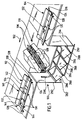
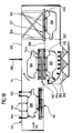
- FIGS. 1 to 17 designated as a whole by 100 first embodiment of a cleaning station for Vehicle bodies include a feed roller conveyor on the input side 104 for the horizontal transport of on skid frame 106 arranged vehicle bodies 108 along the conveying direction 102, that is to say in the illustration of FIGS. 4 to 9 from the left to the right, with the vehicle bodies 108 in one Standard position, in which window openings the Vehicle bodies 108 above the underbody of the vehicle bodies 108 are arranged.
- the input side is connected Feed roller conveyor 104 to a rotating device 110, which serves to rotate the vehicle bodies 108 of the rotating device 110 by a control device (not shown) predefined angles of rotation depending on the vehicle body type To transfer cleaning positions.
- the rotary device is connected along the conveying direction 102 110 an outlet-side discharge roller conveyor 112, onto which the vehicle bodies 108 from the turning device 110 are funded and from where the vehicle bodies 108 for further treatment, for example in one Pretreatment or dip painting bath, are promoted.
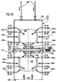
- the feed roller conveyor 104, the rotating device 110 and the Discharge roller conveyor 112 are accommodated together in a cabin 114 (see Fig. 4), which a front wall 116 with an entry opening for the vehicle bodies 108, one Rear wall 118 with an outlet opening for the vehicle bodies 108, a top wall 120 and side walls 122 (see Fig. 10) and on a substantially flat surface 124 is arranged.
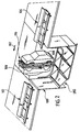
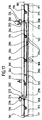
- the feed roller conveyor 104 and the discharge roller conveyor 112 comprise as can best be seen from FIGS. 1 to 3, a substantially extending along the conveying direction 102 rectangular frame 126 with two perpendicular to Direction of conveyance 102 spaced apart longitudinal beams 128 and support feet 130 with which the respective frame 126 supported on the ground 124.
- the frame 126 are one behind the other in the conveying direction 102 several support rollers 132 each rotatably mounted on which cylindrical support body 134 are arranged, the upper support body tips a substantially flat support surface form the skid frame 106 for the skid runners 136.
- the idlers 132 the roller conveyors 104, 112 are known per se Way of (not shown) electric geared motors driven by toothed belt exaggerations.
- each roller conveyor 104, 112 each with an integrated drip pan 138 provided, which is held on the frame 126 and in the conveying direction 102 over the entire length of the relevant roller conveyor 104, 112 and transverse to the conveying direction 102 extends from one of the longitudinal beams 128 to the other.
- the bottom 140 of each sump 138 is inclined and provided with several drain openings (not shown), to which a (also not shown) wet medium discharge line connected.
- each of the roller tracks 104, 112 includes draining elements 142 in the form of baffles 144, which on both sides the longitudinal center plane of the roller conveyor 104, 112 in question and inclined towards the drip pan 138 so that Wet medium from the baffles 144 into the drip pan 138 can drain off.
- the drainer 142 and the drip pan 138 each of the Roller conveyors 104, 112 together form a collection system 146 for the wet medium, which comes from the area above the respective Roller conveyor reaches the roller conveyor.
- FIGS. 4 to 9 are in the range above the roller tracks 104, 112 stationary spray lances 148 and movable spray lances 150 on the ceiling wall 120 of the cabin 114 arranged.
- Spray lances can be in the side walls 122 on either side of the Roller tracks 104, 112 may be arranged.
- Each of the spray lances 148, 150 is designed as a rigid tube, which is located at an end outside the cabin 114 is connected to a wet medium supply and to the opposite, arranged inside the cabin 114 with one with through openings for the wet medium Atomizer plate is closed.
- These tubes can be straight be formed or provided with curvatures. That with the end of the atomizer plate can be tapered be trained.
- the stationary ones Spray lances 148 arranged so that they are completely are located outside the path of the vehicle bodies 108.
- the movable spray lances 150 are in their respective Working position within that of the vehicle bodies 108 when moving through the cabin 114 Area. These movable spray lances 150 are therefore included each one (not shown) electromotive, pneumatic or hydraulic movement device, by means of which these spray lances 150 along the direction of the Arrows 152 moved out of the path of the vehicle bodies 108 or after the vehicle bodies have been transported 108 can be moved back into the working position can.
- the spray lances 148, 150 above the roller conveyors 104, 112 are used to clean the exterior of the vehicle bodies 108.
- the sprayed by these spray lances and or to the respective roller conveyor 104, 112 wet medium dripping from the vehicle bodies 108 either collected directly from the respective collecting pan 138 or caught by the baffles 144 and in the drip pan 138 passed on from where the wet medium flows through the wet medium discharge line and a further treatment, for example cleaning or disposal, is fed.
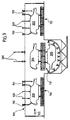
- the one between the feed roller conveyor 104 and the discharge roller conveyor 112 arranged rotator 110 includes, as best 14 shows a rectangular rotating frame 152 with two aligned parallel to the conveying direction 102 Side members 154, which by means of two cross members 156 are interconnected.
- the rotating frame 152 is perpendicular to two bearing blocks 158 by one horizontal axis of rotation aligned with the conveying direction 102 160 rotatably mounted.
- the bearing blocks 158 rest on the Underground 124, which also carries the cabin 114.
- the shaft 166 is through on both sides of the rotating frame 152 the respective side wall 122 of the cabin 114 is passed through, so that the side walls 122 of the cabin 114 as covers serve, through which the rotary drive motor 162, the transmission 164 and the pedestals 158 before cleaning the vehicle bodies 108 used wet medium are protected.
- the passage openings are in the side walls 122, which of the shaft 166 are penetrated, sealed by means of elastic seals 168.
- a receptacle 174a or 174b for one on one Provided skid frame 106 arranged vehicle body 108.
- the two recordings 174a, 174b are the one with respect to one Axis of rotation 160 and the longitudinal direction of the rotating frame 152 containing Level mirror-symmetrical to each other, see above that in the following only the first shown in Fig. 10 above Recording 174a will be described in detail.
- the longitudinal frame beams 170 are on their front and rear Ends by means of end plates 171 and through between the end plates 171 arranged transversely to the longitudinal direction of the longitudinal frame carrier 170 from the one longitudinal frame support 170 to the another longitudinal strut 170 extending cross struts 173 connected with a U-shaped or C-shaped cross section.
- the longitudinal frame supports 170 are in the longitudinal direction of the same spaced apart support rollers 176 to be perpendicular horizontal axes of rotation aligned with the conveying direction 102 178 pivoted.
- the several, for example five, idlers 176, the equidistant are arranged along the conveying direction 102 together a roller conveyor 180 of the holder 174a of the rotating device 110.
- each of the idlers includes 176 cylindrical arranged symmetrically to the longitudinal center plane 172 Support body 182, the upper support body tips together form a support surface 184 for a skid frame 106.
- each of the carrying rollers 176 carries the respective non-tracked Supporting body adjacent, two gear wheels 188 one gear 188 each of two adjacent idlers 176 a chain 190 is tensioned so that the gears 188 and chains 190 together form a chain overdrive, by which the rotation of a support roller 176 on the each adjacent idler roller 176 is transmitted.
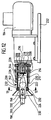
- One of the support rollers 176 is by means of a clutch 192 from an electric gear motor 194 of an external roller conveyor drive part 193 spun.
- the shaft 196 of the idler roller 176a is extended so that they over the (seen in the direction of conveyance 102) right longitudinal frame support 170 to right side wall 122 protrudes from the cabin 114.
- This protruding part of the Shaft 196 is in one of the right cross member 154 of the Rotating frame 152 supported bracket 197 rotatably mounted.
- shaft 196 which is circular Cross-section, a driving pin square in cross-section 198 pushed on, which on one end Has blind hole 200 for receiving the free end of the shaft 196.
- the driving pin 198 is in a radial to the Shaft 196 running through hole of the driving pin 198 screwed threaded pin 202 rotatably on the Wave 196 set.
- a face end of the driving bolt facing away from shaft 196 198 is tapered and has a rounded shape Provide tip 204.
- the driving pin 198 and the shaft 196 form a roller conveyor side first part of clutch 192.
- a cylindrical inner ring 208 with a stepped axial Through hole 210, the narrower, the gear motor 194 facing Section 212 receives the output shaft 206, pushed and by means of a support disc 212 and one Support disc 212 against the shoulder of the stepped through hole 210 pressing cylinder head screw 214, which in one Front axial threaded blind hole of the output shaft 206 is screwed in the axial direction relative to the output shaft 206 fixed.
- a rotatable connection between the output shaft 206 and the inner ring 208 is by means of a feather key 216 made which in an axially aligned Groove 218 on the periphery of the output shaft 206 and one adjoining axial groove on the inside of the narrow area of the stepped through hole 210 of the inner ring 208 intervenes.
- This (not shown) groove on the inner ring 208 extends in the axial direction of the inner ring 208 to to the end facing the geared motor 194, so the inner ring 208 in the groove 218 of the output shaft 206 inserted key 216 pushed onto the output shaft 206 can be.
- a receiving bushing 220 is pushed onto the inner ring 208, which has a hollow cylindrical gear motor 194 facing Section 222 and a gear motor 194 facing away from flared funnel section 224 includes.
- a hollow cylindrical one is in turn on the receiving bushing 220 Outer ring 226 pushed on, which is a thicker wall than has the receptacle 220.
- the receptacle 220 and the outer ring 226 are by means of several screws 228 which radial through holes in the outer ring 226 and in the receptacle Push through 220 and into radial threaded blind holes are screwed into the inner ring 208, rotatably with the inner ring 208 connected.
- FIGS. 12 and 13 are also in the Receiving socket 220, on the funnel section side End of the hollow cylindrical portion 222 of the receptacle 220, two circular segment-shaped driver elements 230 arranged, which by means of screws 232, the radial through holes prevail in the receptacle 220 and in radial Threaded blind holes screwed into the driver elements 230 are rotatably connected to the receptacle 220.
- the mutually facing edges of the driver elements 230 are parallel to each other, as can be seen from Fig. 13 aligned and have such a distance from each other on that the driver elements 230 the square in cross section Section of the driving pin 198 form-fitting between can undertake.
- driver elements 230 For easier insertion of the driving pin 198 between the Driver elements 230 into the hollow cylindrical section 222 of the receptacle 220 are the driver elements 230 on their facing away from the output shaft 206 Face bevelled.
- a sliding guide 236 parallel to the axis of the shaft 196 is guided.
- a moving device 238 provided which, for example a pneumatic cylinder 240 with a slidable therein Piston 242, which by means of a coupling rod 244th engages the sliding carriage 232, so that the sliding carriage 232 in parallel to the direction of the axis of the shaft 196 is moved when the piston 242 out of the pneumatic cylinder 240 is moved out or into it.
- the gear motor 194, the sliding carriage 232, the sliding guide 236 and the movement device 238 for the Shift carriages 232 together form the external roller conveyor drive part 193.
- the rotary drive connection between the gear motor 194 and the driven one Carrier roller 176a can only be produced if the roller conveyor 180 is in the starting position, in which the support surface 184 of the roller conveyor 180 horizontally and is at the same level as the support surfaces of the feed roller conveyor 104 and the discharge roller conveyor 112.
- roller conveyor 180 Skid frame 106 with respect to the rotating frame 152 against a relative movement parallel to the axes of rotation 178 of FIG Carrier rollers 176 through the flanges 186 on the right side Support body 182 secured.
- the locking device 244 includes one at a Rotation of the rotating frame 152 with the same rotating locking part 246 and one when the rotating frame is turned 152 non-rotating drive part 248.
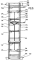
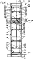
- the locking part 246 includes one parallel to the axes of rotation 178 of the idler rollers 176 aligned threaded spindle 250, which on the longitudinal frame beams 170 and on one of right cross member 154 supported support 251 rotatably mounted is.
- the threaded spindle 250 carries two threaded nuts 252, which are laterally guided so that they turn when the Do not turn threaded spindle 250, but, depending on the direction of rotation, move towards or away from each other.
- a front pusher plate 254 and a rear pusher plate 256 are by means of push rods 258 with the two threaded nuts 252 articulated that the four push rods 258 one Form diamond.
- the front is Push plate 254 articulated via a front push rod 260 with a front bracket 262 and the rear thrust plate 256 articulated via a rear push rod 264 with a rear Bracket 266 connected.
- the two brackets 262, 266 each comprise a rotatable one the shaft 268 held by the consoles 170 of the roller conveyor 180, of a short lever 270 extends in the radial direction, on which the front push rod 260 or the rear Push rod 264 is articulated.
- each of the brackets 262, 266 includes two perpendicular to the Conveying direction 102 long levers 272 spaced apart from one another, which is substantially perpendicular to the short lever 270 extend radially away from shaft 268 and at its free Each end wear a cross-section C-shaped bracket 274.
- the brackets 262, 266 must be around the respective Shaft 268 pivoted away from the relevant crossbar 262 become. As can be seen from Fig. 17, it is this requires the push plates 254 and 256 from each other to move away. As can also be seen from FIGS. 15 or 16 , the threaded nuts 252 must be moved towards each other become.
- a skid frame arranged on the roller conveyor 180 106 can thus by means of the locking device 244 locked or released on the roller conveyor 180 by the threaded spindle 250 in rotation in a suitable direction is transferred.
- the above described locking part rotating with the rotating frame 152 246 of the locking device 244 with the in 14 shows the external locking drive part 248 connected by means of a coupling 278.
- the first part of the clutch 278 on the locking part side is laterally through the right longitudinal frame support 170 protruding part of the threaded spindle 250 and one the end arranged driving pins 198 formed.
- the driving pin 198 arranged on the threaded spindle 250 is formed in the same way as that already above described in connection with the drive of the roller conveyor 180 Driving pin 198, so that on the above description is referred.
- the second part of the clutch 278 on the drive part side and the Latch drive part 248 itself are in the same way formed like the part of the clutch 192 on the drive part side and the one that drives the support rollers 176 of the roller conveyor 180 Roller conveyor drive part 193, so that also in this respect the foregoing description is referenced.
- the drive parts 193, 248, in particular the gear motors 194 outside the cabin 114 arranged and penetrate the receptacles 220 Passage openings in the side walls 122 of the cabin 114, so that the relevant side wall 122 serves as a cover, through which the roller conveyor drive part 193 and the locking drive part 248 before cleaning vehicle bodies 108 used wet medium are protected.
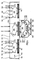
- FIGS. 10 and 14 are in the lower Area of the rotating device 110, i. H. below the axis of rotation 160, stationary spray lances 148a and movable spray lances 150a and in the upper region of the rotating device 110, i.e. H. above the axis of rotation 160, stationary spray lances 148b and movable spray lances 150b on the side walls 122 of FIG Cabin 114 arranged.
- the penetrated by the spray lances Through openings in the side walls 122 are by means of elastic seals 277 sealed.
- the movable spray lances 150a, 150b are by means of electromotive hydraulic or pneumatic movement devices in the horizontal direction from the path of the vehicle bodies 108 retractable to the vehicle bodies 108 from the feed roller conveyor 104 to the in the starting position located roller conveyor 180 of the rotating device 110 or from the roller conveyor 180 of the rotating device 110 to the To be able to promote discharge roller conveyor 112.
- the movable spray lances 150 are dependent on their vehicle body type Working positions movable, in which the atomizing plates of these spray lances are the ones to be sprayed Areas of the respective vehicle body 108 immediately are adjacent or the atomizing plates of the spray lances into the interior of the respective vehicle body 108 protrude to the inner surfaces of the vehicle body 108 to spray.
- movable surge nozzles 280 are arranged, which by means of an electromotive, hydraulic or pneumatic movement device in the vertical direction to a vehicle body arranged on the rotating device 110 108 are movable towards or away from the same.
- Each of the surge nozzles 280 includes a tube, the outside of which the end of the cabin 114 to an end (not shown) Wet medium supply is connected and its other one in the Cabin 114 arranged tapered end and with an outlet opening (not closed by an atomizer plate) is provided for the wet medium.
- a collecting trough 282 of the rotating device 110 is below arranged a collecting trough 282 of the rotating device 110, whose bottom 284 is corrugated so that several cross to Discharge funnel 286 extending conveying direction 102 is formed which have a drain opening at their lowest point 288 have.
- All drain openings 288 are to a wet medium discharge line 290 connected, through which the 282 captured wet medium for further processing, for example cleaning or disposal.
- These spray nozzles can take the form of short pipe sections, for example have, which are fixed to the splash rings 296 are and through the side wall into the interior of the splash rings 296 mouth.
- a partition 279 is provided, which is parallel to the Rotating frame 152 is aligned and both in the longitudinal direction of the vehicle bodies recorded in the recordings 174a, 174b as well as transverse to this longitudinal direction over the in the vehicle bodies recorded in the recordings 174a, 174b 108 survives.
- Each of the partitions 279 is parallel to the longitudinal direction the troughs 281 of the rotating frame 152, which, for example, have a trapezoidal cross section.
- the first embodiment of a cleaning station described above 100 works as follows:
- Is the cleaning station 100 a so-called "body washer” after the body shell and before entering a body coating system is used as a wet medium for cleaning the vehicle bodies 108 as a normal wet medium Tap water with chemical cleaning additives, in particular Additives for degreasing.
- the cleaning station 100 becomes inside a body coating system after a pretreatment bath and before Entry into a dip painting basin used as a rinsing station, so is used as a wet medium for cleaning the vehicle bodies 108 fully demineralized water (demineralized water) was used.
- the wet medium is compared to the ambient temperature elevated temperature of, for example, approximately 60 ° C used.
- Both in the area of the discharge roller conveyor 112 and in the area of the rotating device 110 and the area of the feed roller conveyor 104 is usually the same wet medium for cleaning of vehicle bodies 108 used; However, it is basically also possible in the three areas mentioned different according to composition and / or temperature Use wet media.
- the (in Fig. 4 shown below) first recording 174a of the rotating device 110 includes a second vehicle body 302, which is in a lower cleaning position, in which the second vehicle body 302 by an angle of Is rotated 180 ° from the horizontal.
- the second vehicle body is in this lower cleaning position 302 by means of the spray rings 296 from the outside in Sprayed area of the hood, roof and tailgate.
- a third vehicle body 304 in that shown in FIG. 4 above second receptacle 174b of the rotating device 110 and is in a starting position in which the third vehicle body 304 is not yet opposite the horizontal has been rotated.
- this starting position is an upper cleaning position, in which the third vehicle body 304 by means of the arranged in the upper region of the side walls 122 movable spray lances 150b indoors and outdoors and by means of the in the upper region of the side walls 122 arranged stationary spray lances 148b sprayed outside becomes.
- That of the third vehicle body 304 in the upper cleaning position dripping wet medium first gets into the Troughs 281 of the partition 279 of the second receptacle 174b, flows in these troughs 281 to the front or rear End of the partition 279 and drips from there into the collecting pan 282 without on the in the lower cleaning position located second vehicle body 302 and polluting them.
- a fourth vehicle body 306 on the feed roller conveyor 104 arranged and is there by means of the stationary spray lances 148 and the movable spray lances 150 sprayed from the outside.
- the second one is located Vehicle body 302 in a second side cleaning position, in which this vehicle body by 270 ° is rotated relative to the horizontal, and the third vehicle body 304 is in a first side Cleaning position in which this vehicle body around Is rotated 90 ° with respect to the horizontal.
- the surge nozzles 280 become like this moved far down to the vehicle bodies 302, 304, until the nozzle outlet openings near the inlet openings of arranged in the floor groups of these bodies Cavities arranged and on these entry openings are directed.
- the floor assembly in the first side cleaning position located third vehicle body 304 from the back to the front and the floor pan in the second side cleaning position located second vehicle body 302 is flushed from front to back.
- the optimal working position of the surge nozzles 280 depends on Type of vehicle bodies 108 to be cleaned from time to time is from a (not shown) control unit of the cleaning station 100, which is the rotational movement of the rotating device 110 and the movements of the movable spray lances 150 and the surge nozzle 280 controls depending on the type of vehicle bodies to be cleaned.
- the cleaning cycle for the second vehicle body 302 in the turning device 110 completed so that this body from the turning device 110 can be extended.
- control unit of the cleaning station 100 first of all the spraying process on the discharge roller conveyor 112 has ended, and the movable spray lances 150 in the area of the discharge roller conveyor 112 become the web of the first vehicle body 300 moved out.
- the drive of the discharge roller conveyor 112 is then actuated, so that the first vehicle body 300 (in the illustration 6 to the right) from the cleaning station 100 into a subsequent pretreatment section or painting section is promoted.
- roller conveyor drive part 193 and Locking drive part 148 of the locking device 244 in the manner described above by means of the couplings 192 or 278 with the shaft 196 of the support roller 176a or connected to the threaded spindle 250. It will be successively the geared motors 194 of the locking drive part 148 and the roller conveyor drive part 193 actuated to first locking the second vehicle body ski frame 106 302 to solve and then the second vehicle body 302 by means of the roller conveyor 180 of the first receptacle 174a of the rotating device 110 towards the discharge roller conveyor 112 promote. This extending a vehicle body from the Rotating device 100 is shown in FIG. 3.
- the spraying process on the feed roller conveyor 104 is then interrupted, and the movable spray lances 150 in the area the feed roller conveyor 104 become the fourth Vehicle body 306 moved out.
- the fourth vehicle body 306 is operated the drive of the feed roller conveyor 104 onto the roller conveyor 180 of the first receptacle 174a of the rotating device 110 conveyed and locked there by the direction of rotation of the geared motor 194 of the drive part 248 of the locking device 244 is reversed.
- a fifth vehicle body 308 is shown in the illustration 6 seen from the left) from the in the conveying direction 102 in front of the cleaning station 100 on the Feed roller conveyor 104 promoted.
- the drive point 193 and 248 of the roller conveyor 180 and the Locking device 244 are moved by moving the respective Sliding carriage 232 from the shaft 196 or from the threaded spindle 250 decoupled.
- the movable spray lances 150a and 150b in the area the rotating device 110 is moved into its rest positions, in which they are outside the movement contours of the vehicle bodies 304 and 306 and the rotating frame 152 are arranged are.
- the rotating frame 152 is moved by means of the rotary drive motor 162 (seen in the illustration of FIG. 7) clockwise rotated by an angle of 90 ° around the horizontal axis of rotation 160, until the operating state shown in FIG. 8 is reached in which the third vehicle body 304 is the occupies the second side cleaning position, in which this body turned 270 ° from the horizontal and the fourth vehicle body 306 is the first side Takes cleaning position in which this body is rotated by an angle of 90 ° to the horizontal.
- the surge nozzles 280 are moved into their rest positions, in which they are outside the track of the vehicle bodies 304 and 306 and the rotating frame 152 are arranged, and the rotating frame 152 is operated by means of the rotary drive motor 162 (seen in the viewing direction of Fig. 8) clockwise rotated an angle of 90 ° about the axis of rotation 160 until the in Fig. 9 operating state shown is reached, in which the third vehicle body 304 assumes the initial state, in which this body is not opposite the horizontal is rotated, and the fourth vehicle body 306 occupies the lower cleaning position in which this body to the horizontal by an angle of 180 ° is rotated.
- the vehicle bodies in the rotating device 110 in four different cleaning positions brought in which the vehicle bodies opposite the horizontal by the angles 0 °, 90 °, 180 ° or Are rotated 270 °.
- the vehicle bodies can also be a lesser or a larger number of cleaning positions can be provided, and the vehicle bodies can be in these cleaning positions through any other angle, for example 0 °, 80 ° and 240 °, be rotated with respect to the horizontal.
- the control unit The cleaning station chooses depending on the type of to be cleaned Vehicle body specified for this body type Cleaning positions and the associated working positions the movable spray lances and the surge nozzles.
- the type of vehicle body to be cleaned is the Control device either via a data line or through a suitable input device entered, or the cleaning station is equipped with sensors, with the help of which Control unit the type of vehicle bodies to be cleaned automatically recognizes.
- the total wet medium throughput through the spray lances and surge nozzles of the cleaning station 100 is typically 100 to 1000 m 3 / h.
- a second embodiment shown in FIGS. 18 to 23 the cleaning station 100 differs from that First embodiment described above in that the vehicle bodies 108 from the rotating device 110 'of the second embodiment not in the standard position, in which window openings of the vehicle bodies 108 above of the respective floor group, extend, but in an overhead position, in which the window openings of the vehicle bodies 108 arranged below the floor assembly are.
- each of the two receptacles 174a, 174b not only one roller conveyor, but each a lower roller conveyor 310 and one upper roller conveyor 312, the structure of which is described below becomes; the rotating device 110 'thus has a total of four roller tracks on.
- the cross member 156 of the rotating frame 152 of the rotating device 110 'carry two brackets 314 which extend parallel to the longitudinal direction of the rotating frame 152 and with respect to the longitudinal center plane 172 of the rotating frame 152 are symmetrical to each other.
- brackets 314 there are lower support rollers 316 and upper ones Carrier rollers 318 around perpendicular to the longitudinal direction of the rotating frame 152 aligned horizontal axes of rotation 320 and 322 rotatable stored.
- Each of the support rollers 316, 318 comprises two cylindrical support bodies 324 in the direction of the axes of rotation 320 and 322 from each other are spaced and which with flanges 326 to lateral guidance of a ski frame are provided.
- the support bodies 324 of the lower support rollers 316 have a common one upper tangential plane, which is a lower support surface 330 for a skid frame.
- the supporting bodies 324 have the upper one Support rollers 318 on a common lower tangential plane, which forms an upper support surface 332 for a skid frame.
- the lower support rollers 316 together form the lower roller conveyor 310 of the receptacle 174a, while the upper support rollers 318 together form the upper roller conveyor 312 of the receptacle 174a.
- Each of the support rollers 316, 318 comprises four gears 334, each of which support body 324 of the support roller two are assigned, which together with on the gears 334 overlying tooth chains chain exaggerations for transmission a rotary movement of one idler roller onto one of these Form idler roller adjacent idler roller.
- the shaft 328 of the directly driven lower idler roller 316a is in the same way by means of a clutch 192 with a external roller conveyor drive part 193 'connectable as this already above in connection with the first embodiment the cleaning station has been described.
- the roller conveyor drive part 193 'of the second embodiment differs from that of the first embodiment only by not only having a gear motor 194, but comprises two, which with respect to one the axis of rotation 160 of the rotating frame 152 contained horizontal plane are symmetrical to each other and aligned, so that the shafts 328 of the directly driven idlers 316a the lower roller conveyor 310 of the first receptacle 174a and the lower roller conveyor 310 of the second receptacle 174b simultaneously be coupled to one of the geared motors 194, respectively can.
- each of the two gear motors 194 is open one sliding carriage 232 each on one sliding guide 236 slidably guided, the shifts both sliding carriages 232 by the same movement device 238 is effected and thus among themselves are synchronized.
- the locking devices 244 of the rotating device 110 ' the second embodiment are different from those the first embodiment only in that the locking drive part 248 ', as well as the roller conveyor drive part 193 ', not just a geared motor 194, but two of which includes one with respect to the axis of rotation 160 of the rotating frame 152 contained horizontal plane symmetrically are designed and aligned with each other so that the threaded spindles 250 of the locking parts 246 of the first Recording 174a and the second recording 174b at the same time each one of the geared motors 194 can be coupled.
- the cleaning station 100 on a skid frame of the type shown in FIG. 23 shown type arranged.
- Such a skid frame 106 ' comprises two parallel spaced apart Skid runners 136 'arranged from one another, for example formed as a hollow profile with a rectangular cross-section are.
- Each of the skid runners 136 ' has one in the longitudinal direction of the ski frame 106 'extending substantially rectangular flat lower support surface 338 and one of the lower Support surface 338 facing away, also in the longitudinal direction of the ski frame 106 ', substantially rectangular flat upper contact surface 340.
- the contact surfaces 338 and 340 serve the skid frame 106 'on the lateral surfaces of cylindrical supporting bodies 324 supported by idlers of a roller conveyor.
- the two skid runners 136 'of the skid frame 106' are by means of several transverse struts aligned perpendicular to the skid runners 136 ' and by means of crossbars 342, which are also extend perpendicular to the longitudinal direction of the ski frame 106 ' and via supports 344 on the inner side walls 346 of FIG Skid runners 136 'are held together.
- the crossbeams 342 serve to accommodate those to be carried Vehicle body 108 and are at their ends for this purpose provided with locking elements 348, by means of which the vehicle body 108 can be fixed on the cross members 342 is.
- Gears and chains also not shown
- Drive motors in operative connection so that the Carrier body 354 of the support rollers 356 set in rotation can be.
- the discharge roller conveyor 112 'in the same way with an external roller conveyor drive part 193 connectable by means of a coupling 192 is, as already mentioned above in connection with the roller conveyors of the rotating devices 110 and 110 ' has been.
- the support body 354 of the support rollers 356 of the discharge roller conveyor 112 ' have a common upper tangential plane, which forms a support surface 358 for the skid frame 106 '.
- the cleaning station 100 the rear boundary wall 294 of the collecting trough 282, which is below the rotating device 110 'is arranged.
- the second embodiment of the cleaning station is correct 100 with the first embodiment described above match.
- the second embodiment of cleaning station 100 works as follows:
- a first vehicle body 300 is turned upside down the discharge roller conveyor 112 '.
- first receptacle 174a (shown below in FIG. 18) of the rotating device 110 'is a second vehicle body 302 added, which is in a lower cleaning position in which the second vehicle body 302 rotated by an angle of 180 ° with respect to the horizontal is.
- the second vehicle body is in this lower cleaning position 302 by means of the spray rings 296 from the outside in Area of the bonnet, roof and tailgate with Sprayed wet medium.
- how out 21 shows the underbody of the vehicle body 302 and the interior of the same by means of the lower area of the side walls 122 of the cab 114 arranged movable Spray lances 150a and the side parts of the second vehicle body 302 by means of in the lower area of the side walls 122 of the cabin 114 arranged stationary spray lances 148a sprayed.
- this retracted position is an upper cleaning position, in which the third vehicle body 304 by means of the movable one arranged in the upper region of the side walls 122 Spray lances 150b indoors and outdoors and by means of those arranged in the upper region of the side walls 122 stationary spray lances 148b sprayed outside becomes.
- That of the third vehicle body 304 in the upper cleaning position dripping wet medium first gets into the Troughs 281 of the partition 279 of the second receptacle 174b, flows in these troughs 281 to the front or rear End of the partition 279 and drips from there into the collecting pan 282 without on the in the lower cleaning position located second vehicle body 302 and polluting them.
- the drive of the discharge roller conveyor 112 ′ is then actuated, so that the first vehicle body 300 (in the illustration 18 to the right) from the cleaning station 100 into a subsequent pretreatment section or painting section is promoted.
- roller conveyor drive part 193 'and Locking drive part 148 'of the locking devices 244 in the manner described above by means of the Couplings 192 and 278 with the shafts 328 of the directly driven Carrier rollers 316a of the lower roller tracks 310 of the Recordings 174a, 174b of the rotating device 110 'or with the Threaded spindles 250 of the locking devices 244 connected.
- the locking device 244 becomes the actuated gear motor 194 associated with first receptacle 174a, around the locking of the ski frame 106 'of the second vehicle body 302 to solve.
- roller conveyor 310, 312 of the first receptacle 174a associated gear motor 194 actuated to the second vehicle body 302 by means of the upper roller conveyor 312 of the first receptacle 174a of the rotating device 110 'onto the discharge roller conveyor 112' to promote.
- roller conveyor drive part 193 'and the locking drive part 148 'of the shafts 328 or the threaded spindles 250 uncoupled.
- the rotating frame 152 is operated by means of the rotary drive motor 162 (clockwise in the viewing direction of FIG. 18) rotated by 90 ° around the horizontal axis of rotation 160 until the operating state shown in FIG. 19 is reached.
- Vehicle body 304 After completing the 90 ° rotation, the third is located Vehicle body 304 in a side cleaning position, in which this vehicle body is 90 ° opposite the horizontal is rotated.
- the wet medium supply to the surge nozzles 280 is opened, so that wet medium from the surge nozzles 280 under pressure from 1 to 5 bar into the cavities in the floor assembly of the vehicle body 304 penetrates, this is essentially straight flows through and at the outlet openings of these cavities, which is essentially vertical under the entry openings lie, exits again and reaches the collecting tank 282.
- the vehicle body 304 becomes a particularly good one Cleaning effect achieved.
- the floor assembly in the side cleaning position third vehicle body 304 is from behind flushed forward.
- the optimal working position of the surge nozzles 280 depends on Type of vehicle bodies to be cleaned from time to time is from a (not shown) control unit of the cleaning station 100, which is the rotational movement of the rotating device 110 'and the movements of the movable spray lances 150, 150a, 150b and the surge nozzle 280 controls, depending of the type of vehicle bodies to be cleaned.
- Vehicle body 304 While the vehicle body 304 is in the side Cleaning position is located, it can also by means of Spray rings 296 are sprayed from the outside.
- the spraying process on the feed roller conveyor 104 interrupted, and the moving spray lances 150 in the area of the feed roller conveyor 104 are made the path of the fourth vehicle body 306 moved out.
- the fourth vehicle body 306 is operated the drive of the feed roller conveyor 104 to the lower one Roller conveyor 310 of the first receptacle 174a of the rotating device 110 'conveyed by the sliding carriage 232 of the roller conveyor drive part 193 'are moved so that the geared motors 194 by means of the couplings 192 to the shafts 328 the directly driven idlers 316a, and the assigned to the roller tracks 310, 312 of the first receptacle 174a Gear motor 194 is put into operation.
- a fifth vehicle body 308 is shown in the illustration 20 seen from the left) from the in the conveying direction 102 in front of the cleaning station 100 on the Feed roller conveyor 104 promoted. Then the moveable Spray lances 150 in the area of the feed roller conveyor 104 returned to their work positions for spray cleaning the fifth vehicle body 308 outside perform.
- the one in the lower cleaning position third vehicle body 304 by means of the splash rings 296 from the outside in the area of the bonnet, roof and sprayed the tailgate.
- the underbody is in this lower cleaning position the vehicle body 304 and the interior thereof by means of the arranged in the lower region of the side walls 122 movable spray lances 150a and the side parts of the third vehicle body 304 by means of the lower area of the side walls 122 arranged stationary spray lances 148a sprayed.
Landscapes
- Engineering & Computer Science (AREA)
- Mechanical Engineering (AREA)
- Manufacturing & Machinery (AREA)
- Chemical & Material Sciences (AREA)
- Combustion & Propulsion (AREA)
- Transportation (AREA)
- Vehicle Cleaning, Maintenance, Repair, Refitting, And Outriggers (AREA)
Applications Claiming Priority (2)
| Application Number | Priority Date | Filing Date | Title |
|---|---|---|---|
| DE19950199 | 1999-10-19 | ||
| DE1999150199 DE19950199B4 (de) | 1999-10-19 | 1999-10-19 | Reinigungsstation zum Besprühen und/oder Spülen von Fahrzeugkarosserien und Verfahren zum Reinigen von Fahrzeugkarosserien |
Publications (2)
| Publication Number | Publication Date |
|---|---|
| EP1093864A2 true EP1093864A2 (fr) | 2001-04-25 |
| EP1093864A3 EP1093864A3 (fr) | 2002-05-22 |
Family
ID=7926075
Family Applications (1)
| Application Number | Title | Priority Date | Filing Date |
|---|---|---|---|
| EP00119443A Withdrawn EP1093864A3 (fr) | 1999-10-19 | 2000-09-14 | Station de nettoyage pour asperger et/ou rincer des carrosseries de véhicules et procédé de nettoyage de carrosseries de véhicules |
Country Status (2)
| Country | Link |
|---|---|
| EP (1) | EP1093864A3 (fr) |
| DE (1) | DE19950199B4 (fr) |
Cited By (2)
| Publication number | Priority date | Publication date | Assignee | Title |
|---|---|---|---|---|
| EP2554460A1 (fr) * | 2011-08-04 | 2013-02-06 | Fiat Group Automobiles S.p.A. | Chaîne de montage de véhicules à moteur |
| EP3199246B1 (fr) * | 2016-02-01 | 2023-09-27 | Eisenmann GmbH | Installation, module de traitement et procédé de traitement d'objets |
Families Citing this family (2)
| Publication number | Priority date | Publication date | Assignee | Title |
|---|---|---|---|---|
| DE10340121A1 (de) * | 2003-08-30 | 2005-03-24 | Volkswagen Ag | Vorrichtung zur Erzeugung eines Flüssigkeitsvorhangs |
| DE102014219764A1 (de) * | 2014-09-30 | 2016-03-31 | Dürr Systems GmbH | Fördervorrichtung, Trocknungsanlage und Verfahren zum Fördern von Werkstücken |
Citations (1)
| Publication number | Priority date | Publication date | Assignee | Title |
|---|---|---|---|---|
| DE19730886A1 (de) | 1997-07-18 | 1999-01-21 | Audi Ag | Verfahren zur Herstellung einer Fahrzeugkarosserie und Vorrichtung zur Durchführung des Verfahrens |
Family Cites Families (1)
| Publication number | Priority date | Publication date | Assignee | Title |
|---|---|---|---|---|
| JP2872777B2 (ja) * | 1990-08-23 | 1999-03-24 | マツダ株式会社 | 車体のゴミ除去方法 |
-
1999
- 1999-10-19 DE DE1999150199 patent/DE19950199B4/de not_active Expired - Fee Related
-
2000
- 2000-09-14 EP EP00119443A patent/EP1093864A3/fr not_active Withdrawn
Patent Citations (1)
| Publication number | Priority date | Publication date | Assignee | Title |
|---|---|---|---|---|
| DE19730886A1 (de) | 1997-07-18 | 1999-01-21 | Audi Ag | Verfahren zur Herstellung einer Fahrzeugkarosserie und Vorrichtung zur Durchführung des Verfahrens |
Cited By (4)
| Publication number | Priority date | Publication date | Assignee | Title |
|---|---|---|---|---|
| EP2554460A1 (fr) * | 2011-08-04 | 2013-02-06 | Fiat Group Automobiles S.p.A. | Chaîne de montage de véhicules à moteur |
| WO2013018076A1 (fr) * | 2011-08-04 | 2013-02-07 | Fiat Group Automobiles S.P.A. | Chaîne de montage de véhicule à moteur |
| US9150264B2 (en) | 2011-08-04 | 2015-10-06 | Fiat Group Automobile S.P.A. | Motor vehicle assembly line |
| EP3199246B1 (fr) * | 2016-02-01 | 2023-09-27 | Eisenmann GmbH | Installation, module de traitement et procédé de traitement d'objets |
Also Published As
| Publication number | Publication date |
|---|---|
| DE19950199B4 (de) | 2004-05-19 |
| DE19950199A1 (de) | 2001-05-10 |
| EP1093864A3 (fr) | 2002-05-22 |
Similar Documents
| Publication | Publication Date | Title |
|---|---|---|
| EP1383696B1 (fr) | Dispositif transporteur pour acheminer des pieces d'usinage a travers une zone de traitement en vue du traitement de surface desdites pieces d'usinage | |
| EP2242712B1 (fr) | Système de convoyeur aérien et installation de traitement par immersion équipée d'un système de ce type | |
| DE4410477C1 (de) | Vorrichtung zur Oberflächenbehandlung von Fahrzeugkarosserien | |
| EP1059225B1 (fr) | Procédé et appareillage pour convoyer des carosseries de véhicule à travers un bain de traitement | |
| EP1320418B2 (fr) | Dispositif et proc?d? de traitement de surface de piÌces | |
| EP2242711B2 (fr) | Convoyeur aérien, installation de traitement par immersion avec ce convoyeur, et utilisation du convoyeur | |
| DE10210942B4 (de) | Anlage zum Behandeln, insbesondere zum kataphoretischen Tauchlackieren, von Gegenständen, insbesondere von Fahrzeugkarosserien | |
| EP1426314B9 (fr) | Dispositif et procédé de traitement de surfaces de pièces | |
| DE19950199B4 (de) | Reinigungsstation zum Besprühen und/oder Spülen von Fahrzeugkarosserien und Verfahren zum Reinigen von Fahrzeugkarosserien | |
| DE19950197B4 (de) | Reinigungsstation zum Besprühen und/oder Spülen von Fahrzeugkarosserien und Verfahren zum Reinigen von Fahrzeugkarosserien | |
| DE10210981B4 (de) | Anlage zum Behandeln, insbesondere zum kataphoretischen Tauchlackieren, von Gegenständen, insbesondere von Fahrzeugkarosserien | |
| DE20022634U1 (de) | Vorrichtung zur Oberflächenbehandlung von Werkstücken | |
| EP1093860A2 (fr) | Station d'égouttage pour carrosseries de véhicule | |
| DE4443583C2 (de) | Verfahren und Vorrichtung zum Reinigen und/oder Trocknen von Werkstücken | |
| EP0613733B1 (fr) | Cuvette de traitement pour installation de nettoyage industrielle | |
| DE10121055A1 (de) | Fördervorrichtung zum Fördern von Werkstücken durch einen Behandlungsbereich zur Oberflächenbehandlung der Werkstücke | |
| DE2726227A1 (de) | Vorbehandlungseinrichtung fuer eine lackieranlage | |
| DE1206751B (de) | Vorrichtung zum Reinigen von insbesondere stark verschmutzten Flaschen | |
| DE10066258A1 (de) | Fördervorrichtung zum Fördern von Werkstücken durch einen Behandlungsbereich zur Oberflächenbehandlung der Werkstücke und Verfahren zur Oberflächenbehandlung von Werkstücken | |
| DE10153992A1 (de) | Vorrichtung und Verfahren zur Oberflächenbehandlung von Werkstücken | |
| DE10210943A1 (de) | Anlage zum Behandeln, insbesondere zum kataphoretischen Tauchlackieren, von Gegenständen, insbesondere von Fahrzeugkarosserien | |
| DE10153991A1 (de) | Vorrichtung und Verfahren zur Oberflächenbehandlung von Werkstücken | |
| DE20023583U1 (de) | Fördervorrichtung zum Fördern von Werkstücken durch einen Behandlungsbereich zur Oberflächenbehandlung der Werkstücke | |
| DE10153786A1 (de) | Vorbehandlungsanlage | |
| WO2007121962A2 (fr) | Dispositif d'immobilisation pour chariots de transport et récipients de transport dans des installations de lavage |
Legal Events
| Date | Code | Title | Description |
|---|---|---|---|
| PUAI | Public reference made under article 153(3) epc to a published international application that has entered the european phase |
Free format text: ORIGINAL CODE: 0009012 |
|
| AK | Designated contracting states |
Kind code of ref document: A2 Designated state(s): AT BE CH CY DE DK ES FI FR GB GR IE IT LI LU MC NL PT SE |
|
| AX | Request for extension of the european patent |
Free format text: AL;LT;LV;MK;RO;SI |
|
| PUAL | Search report despatched |
Free format text: ORIGINAL CODE: 0009013 |
|
| AX | Request for extension of the european patent |
Free format text: AL;LT;LV;MK;RO;SI |
|
| 17P | Request for examination filed |
Effective date: 20020620 |
|
| AKX | Designation fees paid |
Designated state(s): AT BE CH CY DE DK ES FI FR GB GR IE IT LI LU MC NL PT SE |
|
| 17Q | First examination report despatched |
Effective date: 20031210 |
|
| STAA | Information on the status of an ep patent application or granted ep patent |
Free format text: STATUS: THE APPLICATION IS DEEMED TO BE WITHDRAWN |
|
| 18D | Application deemed to be withdrawn |
Effective date: 20040401 |