EP1093875B1 - Plaquette de coupe avec de la matière polycristalline frittée dure - Google Patents
Plaquette de coupe avec de la matière polycristalline frittée dure Download PDFInfo
- Publication number
- EP1093875B1 EP1093875B1 EP19990308335 EP99308335A EP1093875B1 EP 1093875 B1 EP1093875 B1 EP 1093875B1 EP 19990308335 EP19990308335 EP 19990308335 EP 99308335 A EP99308335 A EP 99308335A EP 1093875 B1 EP1093875 B1 EP 1093875B1
- Authority
- EP
- European Patent Office
- Prior art keywords
- cutting
- tool
- sintered body
- flank
- edge
- Prior art date
- Legal status (The legal status is an assumption and is not a legal conclusion. Google has not performed a legal analysis and makes no representation as to the accuracy of the status listed.)
- Expired - Lifetime
Links
- 238000005520 cutting process Methods 0.000 title claims description 93
- 239000000463 material Substances 0.000 title description 23
- 239000000758 substrate Substances 0.000 claims description 8
- 229910052582 BN Inorganic materials 0.000 claims description 6
- PZNSFCLAULLKQX-UHFFFAOYSA-N Boron nitride Chemical compound N#B PZNSFCLAULLKQX-UHFFFAOYSA-N 0.000 claims description 6
- 238000005728 strengthening Methods 0.000 claims description 3
- 238000003754 machining Methods 0.000 description 28
- 239000002245 particle Substances 0.000 description 21
- 230000000052 comparative effect Effects 0.000 description 11
- 229910003460 diamond Inorganic materials 0.000 description 11
- 239000010432 diamond Substances 0.000 description 11
- 230000003746 surface roughness Effects 0.000 description 11
- 238000000034 method Methods 0.000 description 5
- 244000145845 chattering Species 0.000 description 4
- 229910000760 Hardened steel Inorganic materials 0.000 description 3
- 229910000831 Steel Inorganic materials 0.000 description 3
- 238000011156 evaluation Methods 0.000 description 3
- 239000010959 steel Substances 0.000 description 3
- 239000006061 abrasive grain Substances 0.000 description 2
- 238000005219 brazing Methods 0.000 description 2
- 229910001018 Cast iron Inorganic materials 0.000 description 1
- 238000004220 aggregation Methods 0.000 description 1
- 230000002776 aggregation Effects 0.000 description 1
- 229910045601 alloy Inorganic materials 0.000 description 1
- 239000000956 alloy Substances 0.000 description 1
- 239000011230 binding agent Substances 0.000 description 1
- 238000003776 cleavage reaction Methods 0.000 description 1
- 230000007423 decrease Effects 0.000 description 1
- 230000000694 effects Effects 0.000 description 1
- 229910052751 metal Inorganic materials 0.000 description 1
- 239000002184 metal Substances 0.000 description 1
- 150000002739 metals Chemical class 0.000 description 1
- 230000007017 scission Effects 0.000 description 1
- 238000005245 sintering Methods 0.000 description 1
Images

Classifications
-
- B—PERFORMING OPERATIONS; TRANSPORTING
- B23—MACHINE TOOLS; METAL-WORKING NOT OTHERWISE PROVIDED FOR
- B23B—TURNING; BORING
- B23B27/00—Tools for turning or boring machines; Tools of a similar kind in general; Accessories therefor
- B23B27/14—Cutting tools of which the bits or tips or cutting inserts are of special material
- B23B27/141—Specially shaped plate-like cutting inserts, i.e. length greater or equal to width, width greater than or equal to thickness
- B23B27/145—Specially shaped plate-like cutting inserts, i.e. length greater or equal to width, width greater than or equal to thickness characterised by having a special shape
-
- B—PERFORMING OPERATIONS; TRANSPORTING
- B23—MACHINE TOOLS; METAL-WORKING NOT OTHERWISE PROVIDED FOR
- B23B—TURNING; BORING
- B23B2200/00—Details of cutting inserts
- B23B2200/28—Angles
- B23B2200/283—Negative cutting angles
Definitions
- This invention relates to a polycrystalline sintered body tool in which sharp cutting edges are formed of a polycrystalline sintered body containing cubic boron nitride to allow high-precision, high-surface roughness cutting of a high-hardness material (see for example US-A-4 714 385).
- cBN sintered body tools For hardened steel, conventional grinding is being replaced by cutting using cBN sintered body tools.
- An object of this invention is to provide a cutting tool which can achieve higher machining accuracy and finished surface roughness than before by improving the cutting edge design of a polycrystalline cBN sintered body tool.
- a polycrystalline hard sintered body cutting tool in which a cutting edge is formed of a polycrystalline hard sintered body containing cubic boron nitride by 20 vol% or over, characterized in that a flank and a rake face of the tool or the flank and an edge-strengthening negative land face are connected together by a curved surface as viewed in section, and that the curved surface has a radius of curvature of 0.1 to 5 ⁇ m.
- the diameter of the cubic boron nitride contained in the polycrystalline sintered body should be 0.01 to 5 ⁇ m.
- the wedge angle at the cutting edge should be set in the range of 90° to 125° for a tool having a negative land and in the range of 65° to 125° for a tool having no negative land.
- a tool substrate made of a cemented carbide should be used.
- the curved surface having a radius of curvature of 5 ⁇ m or under should be formed by edge forming by use of a diamond grinder about #3000 to #14000.
- Figs. 1 and 2 are schematic views of cutting tools of polycrystalline sintered body containing cBN near their cutting edges. Cutting edges are formed using a diamond grinder about #800. With the thus finished cutting edges, a flank 5 and a rake face 4 of the tool (Fig. 2), or the flank 5 and an edge-reinforcing negative land 7 (Fig. 1) are connected through a curved portion 8 (or roundness formed by machining). The radius of curvature R of the curved line in a plane perpendicular to the longitudinal direction of the cutting edge is about 10 ⁇ m. With the conventional machining method, a smaller radius of curvature is not obtainable.
- this curved line 8 makes the actual rake of the cutting edge dull, and becomes a cause of incapability of answering severe requirements for machining accuracy and finished surface roughness in the machining of high-hardness materials.
- the back component force is especially high, and variation in the back component force is also large, so that the degree of sharpness of the edge greatly influences the machining accuracy and finished surface roughness.
- the inventors first studied a method for obtaining a curved line 8 having a radius of curvature R not exceeding 10 ⁇ m, and found out that this object is attainable by forming a cutting edge by grinding with a diamond grinder having an extremely small diamond abrasive grain size of about #3000-#14000.
- a curved line formed between the flank and the rake face or between the flank and the negative land is in the range of 0.1 to 5 ⁇ m, the effective rake of the tool becomes small, so that the sharpness of the cutting edge improves, the cutting resistance, particularly back component force decreases, and better machining accuracy and finished surface roughness than conventional are obtained in the machining of high-hardness material.
- the sintered body used in this invention has the cBN content of 20 vol% or over. Also, since polycrystalline sintered body is less likely to chip due to cleavage than monocrystalline one, the sintered body should be polycrystalline.
- the particle diameter of the cBN particles is preferably in the range of 0.01 to 5 ⁇ m.
- the intersecting angle between the flank and the rake race is less than 65°, the wedge angle of the cutting edge is too small, so that chipping tends to occur at the cutting edge in the initial stage of cutting.
- the intersecting angle between the flank and the rake face or between the rake face and the negative land surface exceeds 125°, an increase in the cutting force becomes remarkable, so that desired machining accuracy is not obtainable.
- the intersecting angle is preferably controlled in the range of 65-125°.
- a steel material may be used for the tool substrate to which the hard sintered body is bonded. But for high-accuracy machining of a high-hardness material, high rigidity is required for the tool substrate, too. Thus a cemented carbide alloy should be used as a tool substrate.
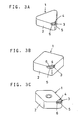
- FIGs. 3A to 3C embodiments of a cutting tool of this invention are shown. These are examples in which this invention is applied to a cutting insert.
- Each insert 1 has a pocket provided at one corner of a tool substrate 2 of cemented carbide.
- a cBN polycrystalline sintered body 3 that of Fig. 3C has a cemented carbide base
- 20 vol% or more cBN particles having a diameter of 0.01-5 ⁇ m is brazed, and then a cutting edge is formed on the sintered body.
- a diamond grinder of #3000-#14000 is used to form a cutting edge 6 at the intersection between the rake face 4 and the flank 5.
- the cutting edge 6 has a sectional shape having an edge-strengthening negative land 7 as shown in Fig. 1, or a sectional shape having no such negative land as shown in Fig. 2, with the portion between the flank 5 and the rake face 4 or the the portion between the flank 5 and the negative land face 7 connected together by a curved surface 8 having a radius of curvature of 0.1 to 5 ⁇ m.
- ⁇ in Figs. 1 and 2 represents the rake angle of the tool
- ⁇ is the relief angle
- ⁇ in Fig. 1 is the negative land angle (that is, intersecting angle between the negative land face 7 and the flank 5)
- ⁇ in Figs. 1 and 2 is the wedge angle at the cutting edge.
- ⁇ is preferably 90° to 125° for the one having the cutting edge structure of Fig. 1 with a negative land, and 65° to 125° for the one having the cutting edge structure of Fig. 2 with no negative land.
- Cutting inserts to which this invention is applied are not limited to the shape shown in Figs. 3A to 3C. Also, tools to which this invention is applied are not limited to cutting inserts.
- Cutting inserts were prepared by brazing a small piece of cBN polycrystalline sintered body containing 50 vol% cBN particles having a particle diameter of about 0.5 ⁇ m to a corner of cemented carbide tool substrate.
- the cutting insert specimens were four kinds as shown in Table 1. Any of them had a cutting edge having the sectional shape shown in Fig. 1.
- the edge was formed by grinding using a diamond grinder of #800, while for Articles B, C, D of the invention, the cutting edges were formed by grinding using a diamond grinder of #3000 or over.
- the radii of curvature of the curved lines 8 formed between the flank 5 and the negative land face 7 differed from each other as shown in Table 1.
- cutting inserts K-S were prepared by brazing cBN polycrystalline sintered bodies containing 63 vol% cBN particles having particle diameter of 0.7 ⁇ m to a corner of a cemented carbide tool substrate.
- cutting edges were formed using a diamond grinder of #8000.
- the radii of curvature of the curved lines at the cutting edges were all about 1 ⁇ m and practically no different from each other.
- the relief angle ( ⁇ in Fig. 1), negative land angle ( ⁇ in Fig. 1), and wedge angle at the cutting edge ( ⁇ in Fig. 1) for each specimen are shown in Table 5.
- the wedge angle at the cutting edge is set suitably with the radius of curvature of the curved line formed at the intersection between the flank and the rake face or between the flank and the negative land face controlled at 5 ⁇ m or under, high-accuracy machining of high-hardness material becomes possible.
- the polycrystalline hard sintered body tool of this invention provides improved sharpness of the cutting edge by reducing the radius of curvature of a curved line formed at the intersection between the flank and the rake face or between the flank and the negative land face by cutting edge forming to a size of 5 ⁇ m or under. This is achieved by diameter adjustment of cBN particles contained in the hard sintered body and by using a diamond grinder that is extremely low in abrasive grain diameter, i.e. #3000 or over.
- a diamond grinder that is extremely low in abrasive grain diameter, i.e. #3000 or over.
Landscapes
- Engineering & Computer Science (AREA)
- Mechanical Engineering (AREA)
- Cutting Tools, Boring Holders, And Turrets (AREA)
Claims (4)
- Outil de coupe à corps fritté dur polycristallin dans lequel une arête coupante (6) est constituée d'un corps fritté dur polycristallin (3) contenant du nitrure de bore cubique à 20% en volume ou plus, caractérisé en ce qu'un flanc (5) et une face inclinée (4) de l'outil ou le flanc (5) et une face de dépouille négative de renforcement de l'arête (7) sont reliés par une surface incurvée (8) vue en coupe et en ce que ladite surface incurvée (8) présente un rayon de courbure de 0,1 à 5 µm.
- Outil de coupe selon la revendication 1, dans lequel le diamètre du nitrure de bore cubique contenu dans ledit corps fritté polycristallin est de 0,01 à 5 µm.
- Outil de coupe selon la revendication 1 ou 2, dans lequel l'angle de taillant au niveau de l'arête de coupe (6) est de l'ordre de 90° à 125° pour un outil ayant une dépouille négative et de l'ordre de 65° à 125° pour un outil n'ayant pas de dépouille négative.
- Outil de coupe selon l'une des revendications 1 à 3, dans lequel ledit corps fritté polycristallin (3) est lié à un substrat d'outil (2) constitué d'un carbure cémenté.
Applications Claiming Priority (1)
| Application Number | Priority Date | Filing Date | Title |
|---|---|---|---|
| JP30113298 | 1998-10-22 |
Publications (2)
| Publication Number | Publication Date |
|---|---|
| EP1093875A1 EP1093875A1 (fr) | 2001-04-25 |
| EP1093875B1 true EP1093875B1 (fr) | 2007-04-18 |
Family
ID=8241691
Family Applications (1)
| Application Number | Title | Priority Date | Filing Date |
|---|---|---|---|
| EP19990308335 Expired - Lifetime EP1093875B1 (fr) | 1998-10-22 | 1999-10-21 | Plaquette de coupe avec de la matière polycristalline frittée dure |
Country Status (2)
| Country | Link |
|---|---|
| EP (1) | EP1093875B1 (fr) |
| DE (1) | DE69935856T2 (fr) |
Cited By (2)
| Publication number | Priority date | Publication date | Assignee | Title |
|---|---|---|---|---|
| CN1950165B (zh) * | 2004-04-30 | 2011-11-16 | 住友电工硬质合金株式会社 | 表面被覆立方晶氮化硼烧结体工具 |
| USD1087188S1 (en) | 2022-10-19 | 2025-08-05 | Milwaukee Electric Tool Corporation | Pipe threading die |
Families Citing this family (3)
| Publication number | Priority date | Publication date | Assignee | Title |
|---|---|---|---|---|
| ZA200007090B (en) * | 1999-12-03 | 2001-06-06 | Sumitomo Electric Industries | Coated PCBN cutting tools. |
| SE530289C2 (sv) * | 2006-10-13 | 2008-04-22 | Seco Tools Ab | Negativt svarvskär med en fas mellan skäregg och släppningssida |
| CN101583450B (zh) * | 2007-01-19 | 2014-01-08 | 住友电气工业株式会社 | 切削工具 |
Family Cites Families (5)
| Publication number | Priority date | Publication date | Assignee | Title |
|---|---|---|---|---|
| US3152385A (en) * | 1961-11-07 | 1964-10-13 | Norton Co | Ceramic tools |
| JPS57144604A (en) * | 1981-03-03 | 1982-09-07 | Ngk Spark Plug Co Ltd | Surface covered throw away tip |
| JPS59219122A (ja) * | 1983-05-27 | 1984-12-10 | Sumitomo Electric Ind Ltd | 被覆超硬合金工具及びその製造法 |
| US4714385A (en) * | 1986-02-27 | 1987-12-22 | General Electric Company | Polycrystalline diamond and CBN cutting tools |
| SE501913C2 (sv) * | 1993-10-21 | 1995-06-19 | Sandvik Ab | Skär för skärande verktyg |
-
1999
- 1999-10-21 DE DE1999635856 patent/DE69935856T2/de not_active Expired - Lifetime
- 1999-10-21 EP EP19990308335 patent/EP1093875B1/fr not_active Expired - Lifetime
Cited By (2)
| Publication number | Priority date | Publication date | Assignee | Title |
|---|---|---|---|---|
| CN1950165B (zh) * | 2004-04-30 | 2011-11-16 | 住友电工硬质合金株式会社 | 表面被覆立方晶氮化硼烧结体工具 |
| USD1087188S1 (en) | 2022-10-19 | 2025-08-05 | Milwaukee Electric Tool Corporation | Pipe threading die |
Also Published As
| Publication number | Publication date |
|---|---|
| EP1093875A1 (fr) | 2001-04-25 |
| DE69935856D1 (de) | 2007-05-31 |
| DE69935856T2 (de) | 2007-09-06 |
Similar Documents
| Publication | Publication Date | Title |
|---|---|---|
| US6652201B2 (en) | Ball end mill | |
| EP1122010B1 (fr) | Outil coupant de métal dur fritté polycristallin | |
| EP1850992B1 (fr) | Plaquette de coupe dotee d'un angle de chanfrein variable au niveau du tranchant de pointe | |
| KR102214373B1 (ko) | 절삭 인서트 | |
| CN105873701B (zh) | 切削刀具及其制造方法 | |
| EP1859882B1 (fr) | Outil de decoupe au cbn pour un usinage de grande efficacite et de grande qualite | |
| EP0695596B1 (fr) | Outil de coupe rotatif et sa méthode de fabrication | |
| EP0559961A1 (fr) | Fraise à queue à haute rigidité | |
| KR20140020952A (ko) | 날끝 교환식 볼 엔드밀 | |
| EP3162779A1 (fr) | Objet fritté de nitrure de bore cubique et outil de coupe | |
| JP2001212703A (ja) | 多結晶硬質焼結体切削工具 | |
| KR960007687Y1 (ko) | 엔드밀 | |
| EP1093875A1 (fr) | Plaquette de coupe avec de la matière polycristalline frittée dure | |
| JP2003175408A (ja) | 多結晶硬質焼結体スローアウェイチップ | |
| JP2000190108A (ja) | 多結晶硬質焼結体切削工具 | |
| JP2949973B2 (ja) | スローアウェイチップ | |
| JPH0321856Y2 (fr) | ||
| KR102316725B1 (ko) | 다결정다이아몬드 소재의 절삭날이 결합된 엔드밀 | |
| JPH08192305A (ja) | スローアウェイチップおよびその製造方法 | |
| KR100676248B1 (ko) | 회전하는 금속공작물을 선삭하는 방법 | |
| JPH04310312A (ja) | エンドミルまたはブレード | |
| JPS61100302A (ja) | ウルツ鉱型窒化硼素焼結体切削工具刃先のランド形成方法 | |
| JP2005238367A (ja) | ミーリング工具およびその検査方法 | |
| JPH088012Y2 (ja) | 回転工具 | |
| JPS6140434Y2 (fr) |
Legal Events
| Date | Code | Title | Description |
|---|---|---|---|
| PUAI | Public reference made under article 153(3) epc to a published international application that has entered the european phase |
Free format text: ORIGINAL CODE: 0009012 |
|
| AK | Designated contracting states |
Kind code of ref document: A1 Designated state(s): DE FR GB IT SE |
|
| AX | Request for extension of the european patent |
Free format text: AL;LT;LV;MK;RO;SI |
|
| 17P | Request for examination filed |
Effective date: 20010419 |
|
| AKX | Designation fees paid |
Free format text: DE FR GB IT SE |
|
| GRAP | Despatch of communication of intention to grant a patent |
Free format text: ORIGINAL CODE: EPIDOSNIGR1 |
|
| GRAS | Grant fee paid |
Free format text: ORIGINAL CODE: EPIDOSNIGR3 |
|
| GRAA | (expected) grant |
Free format text: ORIGINAL CODE: 0009210 |
|
| AK | Designated contracting states |
Kind code of ref document: B1 Designated state(s): DE FR GB IT SE |
|
| RIN2 | Information on inventor provided after grant (corrected) |
Inventor name: NAKAI, TETSUO,ITAMI WORKS OF SUMITOMO ELECTRIC IND Inventor name: TOMITA, KUNIHIRO,ITAMI WORKS OF SUMITOMO ELECTRIC Inventor name: SAHASHI, TOSHIYUKI,ITAMI WORKS OF SUMITOMO ELECTRI Inventor name: KANADA, YASUYUKI,ITAMI WORKS OF SUMITOMO ELECTRIC |
|
| REF | Corresponds to: |
Ref document number: 69935856 Country of ref document: DE Date of ref document: 20070531 Kind code of ref document: P |
|
| REG | Reference to a national code |
Ref country code: SE Ref legal event code: TRGR |
|
| ET | Fr: translation filed | ||
| PLBE | No opposition filed within time limit |
Free format text: ORIGINAL CODE: 0009261 |
|
| STAA | Information on the status of an ep patent application or granted ep patent |
Free format text: STATUS: NO OPPOSITION FILED WITHIN TIME LIMIT |
|
| 26N | No opposition filed |
Effective date: 20080121 |
|
| REG | Reference to a national code |
Ref country code: FR Ref legal event code: PLFP Year of fee payment: 18 |
|
| REG | Reference to a national code |
Ref country code: FR Ref legal event code: PLFP Year of fee payment: 19 |
|
| REG | Reference to a national code |
Ref country code: FR Ref legal event code: PLFP Year of fee payment: 20 |
|
| PGFP | Annual fee paid to national office [announced via postgrant information from national office to epo] |
Ref country code: FR Payment date: 20180913 Year of fee payment: 20 |
|
| PGFP | Annual fee paid to national office [announced via postgrant information from national office to epo] |
Ref country code: SE Payment date: 20181011 Year of fee payment: 20 Ref country code: DE Payment date: 20181009 Year of fee payment: 20 |
|
| PGFP | Annual fee paid to national office [announced via postgrant information from national office to epo] |
Ref country code: IT Payment date: 20181018 Year of fee payment: 20 Ref country code: GB Payment date: 20181017 Year of fee payment: 20 |
|
| REG | Reference to a national code |
Ref country code: DE Ref legal event code: R071 Ref document number: 69935856 Country of ref document: DE |
|
| REG | Reference to a national code |
Ref country code: GB Ref legal event code: PE20 Expiry date: 20191020 |
|
| REG | Reference to a national code |
Ref country code: SE Ref legal event code: EUG |
|
| PG25 | Lapsed in a contracting state [announced via postgrant information from national office to epo] |
Ref country code: GB Free format text: LAPSE BECAUSE OF EXPIRATION OF PROTECTION Effective date: 20191020 |