EP1093952A2 - Absperrventil für einen Tank - Google Patents
Absperrventil für einen Tank Download PDFInfo
- Publication number
- EP1093952A2 EP1093952A2 EP00121234A EP00121234A EP1093952A2 EP 1093952 A2 EP1093952 A2 EP 1093952A2 EP 00121234 A EP00121234 A EP 00121234A EP 00121234 A EP00121234 A EP 00121234A EP 1093952 A2 EP1093952 A2 EP 1093952A2
- Authority
- EP
- European Patent Office
- Prior art keywords
- tank
- valve
- valve body
- shut
- valve seat
- Prior art date
- Legal status (The legal status is an assumption and is not a legal conclusion. Google has not performed a legal analysis and makes no representation as to the accuracy of the status listed.)
- Granted
Links
- 239000000945 filler Substances 0.000 claims abstract description 44
- 238000007789 sealing Methods 0.000 claims description 25
- 238000006073 displacement reaction Methods 0.000 claims description 3
- 230000000694 effects Effects 0.000 abstract description 3
- 239000012530 fluid Substances 0.000 abstract 1
- 238000005429 filling process Methods 0.000 description 13
- 239000002828 fuel tank Substances 0.000 description 4
- 239000000446 fuel Substances 0.000 description 3
- 239000007789 gas Substances 0.000 description 3
- 238000000034 method Methods 0.000 description 3
- 230000001419 dependent effect Effects 0.000 description 2
- 239000002184 metal Substances 0.000 description 2
- 238000013022 venting Methods 0.000 description 2
- 230000015572 biosynthetic process Effects 0.000 description 1
- 238000012790 confirmation Methods 0.000 description 1
- 238000010276 construction Methods 0.000 description 1
- 238000001514 detection method Methods 0.000 description 1
- 230000007613 environmental effect Effects 0.000 description 1
- 210000003746 feather Anatomy 0.000 description 1
- 238000010438 heat treatment Methods 0.000 description 1
- 238000007654 immersion Methods 0.000 description 1
- 239000000314 lubricant Substances 0.000 description 1
- 238000004519 manufacturing process Methods 0.000 description 1
- 230000036316 preload Effects 0.000 description 1
- 230000002265 prevention Effects 0.000 description 1
- 230000001953 sensory effect Effects 0.000 description 1
- 239000000126 substance Substances 0.000 description 1
Images
Classifications
-
- B—PERFORMING OPERATIONS; TRANSPORTING
- B60—VEHICLES IN GENERAL
- B60K—ARRANGEMENT OR MOUNTING OF PROPULSION UNITS OR OF TRANSMISSIONS IN VEHICLES; ARRANGEMENT OR MOUNTING OF PLURAL DIVERSE PRIME-MOVERS IN VEHICLES; AUXILIARY DRIVES FOR VEHICLES; INSTRUMENTATION OR DASHBOARDS FOR VEHICLES; ARRANGEMENTS IN CONNECTION WITH COOLING, AIR INTAKE, GAS EXHAUST OR FUEL SUPPLY OF PROPULSION UNITS IN VEHICLES
- B60K15/00—Arrangement in connection with fuel supply of combustion engines or other fuel consuming energy converters, e.g. fuel cells; Mounting or construction of fuel tanks
- B60K15/03—Fuel tanks
- B60K15/04—Tank inlets
-
- B—PERFORMING OPERATIONS; TRANSPORTING
- B60—VEHICLES IN GENERAL
- B60K—ARRANGEMENT OR MOUNTING OF PROPULSION UNITS OR OF TRANSMISSIONS IN VEHICLES; ARRANGEMENT OR MOUNTING OF PLURAL DIVERSE PRIME-MOVERS IN VEHICLES; AUXILIARY DRIVES FOR VEHICLES; INSTRUMENTATION OR DASHBOARDS FOR VEHICLES; ARRANGEMENTS IN CONNECTION WITH COOLING, AIR INTAKE, GAS EXHAUST OR FUEL SUPPLY OF PROPULSION UNITS IN VEHICLES
- B60K15/00—Arrangement in connection with fuel supply of combustion engines or other fuel consuming energy converters, e.g. fuel cells; Mounting or construction of fuel tanks
- B60K15/03—Fuel tanks
- B60K15/077—Fuel tanks with means modifying or controlling distribution or motion of fuel, e.g. to prevent noise, surge, splash or fuel starvation
- B60K2015/0772—Floats in the fuel tank
-
- Y—GENERAL TAGGING OF NEW TECHNOLOGICAL DEVELOPMENTS; GENERAL TAGGING OF CROSS-SECTIONAL TECHNOLOGIES SPANNING OVER SEVERAL SECTIONS OF THE IPC; TECHNICAL SUBJECTS COVERED BY FORMER USPC CROSS-REFERENCE ART COLLECTIONS [XRACs] AND DIGESTS
- Y10—TECHNICAL SUBJECTS COVERED BY FORMER USPC
- Y10T—TECHNICAL SUBJECTS COVERED BY FORMER US CLASSIFICATION
- Y10T137/00—Fluid handling
- Y10T137/7287—Liquid level responsive or maintaining systems
- Y10T137/7358—By float controlled valve
- Y10T137/7439—Float arm operated valve
- Y10T137/7446—With flow guide or restrictor
-
- Y—GENERAL TAGGING OF NEW TECHNOLOGICAL DEVELOPMENTS; GENERAL TAGGING OF CROSS-SECTIONAL TECHNOLOGIES SPANNING OVER SEVERAL SECTIONS OF THE IPC; TECHNICAL SUBJECTS COVERED BY FORMER USPC CROSS-REFERENCE ART COLLECTIONS [XRACs] AND DIGESTS
- Y10—TECHNICAL SUBJECTS COVERED BY FORMER USPC
- Y10T—TECHNICAL SUBJECTS COVERED BY FORMER US CLASSIFICATION
- Y10T137/00—Fluid handling
- Y10T137/7287—Liquid level responsive or maintaining systems
- Y10T137/7358—By float controlled valve
- Y10T137/7439—Float arm operated valve
- Y10T137/7465—Assembly mounted on and having reciprocating valve element coaxial with inlet pipe
Definitions
- the invention relates to a shut-off valve for a tank.
- the shut-off valve in a filling path leading into the tank is arranged.
- the invention can also be used in other tank systems to avoid overfilling a tank.
- venting devices are provided which are used for Prevention of the escape of harmful components with appropriate Filters are equipped. These venting devices usually leave only one slow, quasi-static pressure equalization.
- Tanks the content of which is used up over time, must be used again at regular intervals be filled, for which purpose, in particular in the case of motor vehicle tanks, only a temporary one Connection to a filling line is made.
- the tank must be opened when refilling be, whereby there is an escape of gases in the tank at the Filling opening can come.
- the tank in the prior art, for example in DE 198 02 078 A1 therefore becomes the filling opening with an automatically closing non-return flap provided that when removing the fill line, for example after a Pulling out a fuel nozzle from a tank filler opening, the tank immediately again closes.
- gases in the tank can re-exist penetrate outside. This is sometimes provided by a filling device Suction devices encountered, which collect the escaping gases.
- the filling device at a sudden increase in back pressure, for example in the event of a Immersion of the mouth opening of a fuel nozzle in the filling surface of a Tanks or a tank filler neck occurs, switches off automatically.
- the tank filler neck towards the actual tank tapered to reach a maximum fill level in the nozzle cause a temporary back pressure, which means that the filling device is switched off prompted.
- the tapering formation of the tank filler neck extends the to Filling the tank time required.
- the invention is based on the object, a shut-off valve for one To create a tank, which in addition to high tightness when closed fast, complete filling of the tank allowed.
- a shut-off valve for a tank comprising a Filling tube with a filling-side valve seat and a tank-side valve seat, which in Flow direction of the filler tube are arranged spaced apart from one another Valve body with a sealing element that is movable between the valve seats is arranged to one or the other depending on the position of the valve body to rest another valve seat, with the valve body in the direction of the filling side Valve seat is biased to the filler pipe against the in a rest position fill-side valve seat seal, and taking the bias of the valve body by the flow pressure of a medium to be filled in the direction of the tank side Valve seat is set to be overcome, and a level-controlled Stop device for stopping the movement of the valve body in the direction of the tank-side valve seat in a position in which the sealing element from the medium to be filled is held around the valve seats so that it can flow around the impact of the anchor device when a predetermined one is reached Level is lifted in the tank.
- the solution according to the invention combines high tightness with a precise one Switching off a filling process when a predetermined fill level is reached in the tank, so that annoying refueling processes can be omitted.
- By closing of the valve body when the fill level is reached a back pressure is caused, which leads to a shutdown of the filling device.
- the closing of the valve body is directly dependent on the level in the tank, dynamic effects switched off between the tank filler neck and the actual tank. In this case in particular, it is no longer necessary to include the tank filler neck a cross-section tapering towards the tank, so that the shut-off device according to the invention also a wider tank filler neck and so that it can be filled quickly.
- the preload of the valve body causes the shut-off valve to be in the rest position a permanent seal of the tank from the environment is guaranteed.
- a permanent seal of the tank from the environment is guaranteed.
- the sealing element can be formed integrally with the valve body or as a separate one Element to be attached to this.
- valve seats are on Inner wall sections of the filler tube formed, the inner width or Diameter is larger than the inside width or the inside diameter of one Flow opening of the filler pipe. This leaves a large inside width for filling received on the filler pipe.
- the flow resistance of the filler pipe can thus be kept low, so that a filling process, especially at higher ones Temperatures can be carried out quickly and without interruption.
- valve seats are preferably inclined with respect to the flow direction Wall sections formed. This allows self-centering of the Realize sealing element in relation to the valve seats. Moreover, it will be a good process of residual quantities of the filling medium in the area of the valve seats in the direction of Tanks achieved.
- the outer width or Outer diameter of the sealing element is smaller than the inner width or Inner diameter of an enlarged, arranged between the valve seats Pipe section, however, larger than the inner width or the inner diameter of the Flow opening of the filler pipe. Due to the expanded pipe section Flow resistance of the filler pipe in the area of the valve body is kept low, so that it does not become one even with larger quantities of the filling device early shutdown can come.
- the cross sections of the pipe sections are included not necessarily round, but can also have other profile shapes.
- valve body To reduce the mass of the valve body, it is designed as a hollow piston. A return of the valve body to the rest position can thus be carried out with only a small amount Spring forces take place. This in turn allows filling even with a small amount Delivery pressures.
- valve body can be further reduced if according to a further, preferred embodiment of the valve body on its filler-side valve seat-facing end face than in the direction of the filler-side Valve seat tapered bulge is formed.
- the valve body is on an inner wall portion of the Filler tube slidably guided.
- the filling medium acts as a lubricant, which results in a particularly smooth bearing of the valve body, so that the restoring forces for sealing the tank can be kept low the valve body can be easily moved into a switch-off position by the flow pressure, in which the sealing element comes to rest against the tank-side valve seat.
- the valve body is against the inner wall of the spring Supported filler tube, the bias is set such that the valve body automatically seals with its sealing element against the filling-side valve seat is pressed, but the seal is filled by the flow pressure of a Medium can be canceled.
- the space between the Valve seats with a portion of the filler tube and / or the tank downstream of the valve seat on the tank side when the sealing element is in contact with the tank side Valve seat connected effective overflow line, which is a defined throttle point for has a slow pressure equalization. So that after closing the Valve body against the tank-side valve seat in the filler pipe downstream of the medium located on the tank-side valve seat drain slowly into the tank until the Valve body back against the filler-side valve seat due to the reset Plant is brought.
- a spatially compact as well as robust and failure-prone construction results itself by the design of the anchor device with a relocatable Stop protrusion for stopping the movement of the valve body in one Pipe section of the filler pipe between the tank-side valve seat and the tank is arranged against which a support element of the valve body in a stopped Position is present and which is coupled to a level sensor, the Stop projection depending on the level sensor when reaching a predetermined level in the tank is moved from its stop position to to release a further displacement path for the support element of the valve body.
- a float arranged in the tank can, for example, serve as a fill level signal transmitter be used, the mechanical when reaching a certain level or generated electrical signal that in a control signal for the stop projection is implemented. This can be done using a mechanical linkage, for example, that connects the float to the anchor device. Instead of the mechanical Linkage can also be an electrical actuator to confirm the anchor device be used.
- the stop device preferably comprises a flap which is transverse to an axis Flow direction is pivotable, and which has an opening at one Relocation of the stop projection as a result of reaching a predetermined one Level in the tank in the position of the stop projection is pivotable.
- This can be switched off in a particularly simple manner Reaching the fill level. That remains during the filling process Support element of the valve body supported on the stop projection until this is moved as a result of pivoting out of its supporting position. In their place enters the opening through which the support element of the valve body penetrates, so that this is moved further in the direction of the tank, whereby the sealing element of the Valve body against the tank-side valve seat to the system and the shutdown the filling device causes.
- the flap of the anchor device is as plate-like element, for example as a sheet metal element, with a around the transverse axis curved edge portion formed as a stop projection against which Support element of the valve body can be brought into contact laterally on a support surface.
- the opening on the plate-like element connects to the stop projection in order when the plate-like element is pivoted about the transverse axis into the position to reach the support surface, the opening being larger than the support surface.
- the plate-like element can be produced, for example, as a simple bent sheet metal part become.
- the embodiment shows a shut-off valve for a fuel tank Motor vehicle, which is arranged in a tank filler neck.
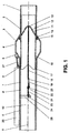
- Figure 1 shows that Shut-off valve in a rest position, in which the shut-off valve is not one in the figure seals tank shown to the environment to prevent the escape of gaseous Avoid substances that form above the tank content.
- the shut-off valve comprises a filler pipe 1, one on the right-hand side in FIG Has filler opening, through which fuel is introduced during a filling process and Another through a through opening 10 formed in the filler pipe 1 Section of the tank filler neck or the tank is supplied.
- a first pipe section 2 with a substantially constant cross section an expanded pipe section 4 with a larger inner width to which one connects second pipe section 6, the inner width of which is essentially that of the first Pipe section 2 corresponds.
- the expanded pipe section 4 is in each case one wall section 3 inclined to the longitudinal central axis X of the through opening 10 or 5 connected to the first pipe section 2 or the second pipe section 6.
- the illustrated embodiment each have the pipe sections 2 to 6 circular inner profile, so that the inclined wall sections 3 and 5, respectively conical valve seats for a valve body 11 to be explained in more detail below form.
- the inner wall of the second pipe section 6 has an inclined one on the tank side Wall section 5 immediately adjoining inner paragraph, which in the direction of Tanks in a level 9 that ends as a stop for a spring support of the Valve body 11 is used. Furthermore, on the inner wall of the second pipe section 6 Guide grooves 7 are provided, each with a tank-side limit stop 8, in the sections of the valve body 11 are slidable in the direction of the longitudinal central axis X. intervention.
- the valve body 11 is a hollow cylinder with a in the direction of the fill opening tapering bulge 12 formed on a front end 13th is rounded.
- the bulge is 12 arranged concentrically to the longitudinal central axis X.
- the valve body comprises 11 a radial ring section 14 which connects to the bulge 12 on the rear and protrudes into the expanded space of the expanded pipe section 4.
- the Ring section 14 carries on its radial outside an elastic sealing element 15, for example an O-ring, which depending on the position of the valve body 11 with the fill-side valve seat 3 or the tank-side valve seat 5 are brought into contact can. In the rest position shown in Figure 1, the sealing element 15 is in System against the filler-side valve seat 3.
- This guide arrangement includes radial Guide projections 17 which slide in the guide grooves 7 of the filler pipe 1 and thus secure it against twisting in the filler pipe 1.
- the valve body 11 is on the back via a spring 16 against the step 9 of the filler pipe 1 supported.
- the bias of the spring 16 is set such that the Valve body 11 with its sealing element 15 sealing against the filling side Valve seat 3 is pressed.
- the Valve body 11 are displaced in the direction of the tank, the spring 16 is compressed. This shifting is necessary when filling the tank.
- the bias of the spring 16 is chosen such that the seal by the flow pressure of a medium to be filled, as it is by conventional Filling device is provided, can be picked up.
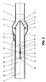
- the shut-off valve further comprises a level-controlled stop device 20 for stopping the movement of the valve body 11 in the direction of the tank side Valve seat 5, so that the sealing element 15 of the Valve body 11 does not initially come into contact with the tank-side valve seat 5, but, as shown in Figure 2, in a central position between the valve seats 3 and 5 persists, in which the valve body 11 is flowed around by the medium to be filled.
- the medium to be filled presses on the end face, d. H. the bulge 12 of the Valve body 11 and is expanded by this in the direction of the expanded space of the Pipe section 4 deflected to pass from there to the rear of the valve body 11 to flow through the second pipe section 6 to the tank.
- the one in the second Pipe section 6 arranged stop device 20 is not essential Flow obstacle, since these are with their during the filling process Elements extends essentially in the direction of the longitudinal central axis X.
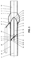
- the level-controlled stop device 20 is designed such that when reached a predetermined level in the tank, the impact against the Valve body 11 is lifted, so that this by the flow pressure from the in Figure 2 shown position with the arranged between the valve seats 3 and 5 Sealing element 15 is moved into the switch-off position shown in Figure 3, in which the Sealing element 15 bears against the tank-side valve seat 5.
- the Stop device 20 a flap in the second pipe section 6 about an axis 25 is pivotally mounted transversely to the longitudinal center axis direction X.
- the flap is actuated by a fill level signal transmitter, which is here formed as a floating body 26 arranged in the tank and in the figures is shown schematically.
- This float 26 is via a double joint linkage 27 coupled to a housing section and via one in the second Pipe section 6 protruding actuating rod 28 with the stop device 20 coupled.
- the floats Body 26 this movement on the actuating rod 28 on the Stop device 20 is transmitted to cancel their impact.
- the Actuating rod 28 engages an off-axis fastening section 24 of the flap so that there is a long lever arm with respect to the transverse axis 25, thus already low actuating forces are sufficient to pivot the flap.
- a mechanical actuating rod 28 can alternatively one in sensory detection of the fill level is not shown in the figures, for example by adding a level sensor when a certain level is reached Fills level and triggers an electrical confirmation device that To pivot the flap of the stop device 20.
- the flap of the stop device 20 comprises a stop projection 21 which around the Transverse axis 25 is bent.
- the flap of the stop device 20 extends in the rest position and when Filling essentially in the direction of the longitudinal central axis X, so that the free Flow diameter of the passage opening 10 through this only slightly is restricted. Only the stop projection 21 extends perpendicular to the Flow direction.
- An opening 22 is also provided on the flap, in the case of a publisher of the stop projection 21 as a result of reaching a predetermined fill level is pivoted into the position of the stop projection 21 in the tank. Since the Opening 22 is larger than the stop surface 19 of the support element 18, can the latter, caused by the acting on the valve body 11 Flow pressure, penetrate through the opening 22, so that for the valve body 11th a further displacement path is released, which enables the valve body 11, to complete the second pipe section 6 against the tank-side valve seat 5. The hereby suddenly built up back pressure causes an immediate shutdown the filling device. This state is illustrated in Figure 3, in which the Flap of the stop device 20 is pivoted to the maximum.
- the shut-off valve shown in the exemplary embodiment enables fast and precise switching off of a filling process, so that an automatic filling up to the fill level of the tank without manual refill measures. If a filling process is ended prematurely without the one shown in FIG Position is reached, it is still ensured that the valve body 11 after the Completion of the filling process immediately in the position shown in Figure 1 returns to seal the tank to the outside.
Landscapes
- Engineering & Computer Science (AREA)
- Transportation (AREA)
- Sustainable Energy (AREA)
- Chemical & Material Sciences (AREA)
- Combustion & Propulsion (AREA)
- Life Sciences & Earth Sciences (AREA)
- Mechanical Engineering (AREA)
- Sustainable Development (AREA)
- Filling Or Discharging Of Gas Storage Vessels (AREA)
- Safety Valves (AREA)
- Feeding And Controlling Fuel (AREA)
- Self-Closing Valves And Venting Or Aerating Valves (AREA)
- Electrical Discharge Machining, Electrochemical Machining, And Combined Machining (AREA)
- Cooling, Air Intake And Gas Exhaust, And Fuel Tank Arrangements In Propulsion Units (AREA)
- Lift Valve (AREA)
Abstract
Description
- Figur 1
- einen Längsschnitt durch ein Absperrventil für einen Kraftstofftankbehälter eines Kraftfahrzeuges in einer Ruhestellung, in der der Kraftstofftank zur Umgebung hin abgedichtet ist,
- Figur 2
- einen Längsschnitt entsprechend Figur 1 während eines Befüllungsvorganges, und in
- Figur 3
- einen Längsschnitt entsprechend Figur 1 zur Veranschaulichung des Abschaltens eines Befüllungsvorganges.
- 1
- Einfüllrohr
- 2
- erster Rohrabschnitt
- 3
- einfüllseitiger Ventilsitz / geneigter Wandabschnitt
- 4
- erweiterte Rohrabschnitt
- 5
- tankseitiger Ventilsitz / geneigter Wandabschnitt
- 6
- zweiter Rohrabschnitt
- 7
- Führungsnut
- 8
- Anschlag der Führungsnut
- 9
- Stufe
- 10
- Durchgangsöffnung
- 11
- Ventilkörper
- 12
- Hervorwölbung
- 13
- Frontende des Ventilkörpers
- 14
- Ringabschnitt des Ventilkörpers
- 15
- Dichtelement
- 16
- Feder
- 17
- Führungsabschnitt des Ventilkörpers
- 18
- Abstützelement des Ventilkörpers
- 19
- Abstützfläche des Ventilkörpers
- 20
- Anschlageinrichtung
- 21
- Anschlagvorsprung
- 22
- Öffnung der Anschlageinrichtung
- 23
- Ablaufausnehmung
- 24
- Befestigungsabschnitt
- 25
- Querachse
- 26
- Schwimmkörper
- 27
- Doppelgelenk-Gestänge
- 28
- Betätigungstange
- X
- Längsmittelachse
Claims (12)
- Absperrventil für einen Tank, umfassend ein Einfüllrohr (1) mit einem einfüllseitigen Ventilsitz (3) und einem tankseitigen Ventilsitz (5), die in Durchströmrichtung des Einfüllrohres (1) voneinander beabstandet angeordnet sind, einen Ventilkörper (11) mit einem Dichtelement (15), der zwischen den Ventilsitzen (3, 5) bewegbar angeordnet ist, um je nach Stellung des Ventilkörpers (11) gegen den einen oder den anderen Ventilsitz (3, 5) anzuliegen, wobei der Ventilkörper (11) in Richtung des einfüllseitigen Ventilsitzes (3) vorgespannt ist, um in einer Ruhestellung das Einfüllrohr (1) gegen den einfüllseitigen Ventilsitz (3) abzudichten, und wobei die Vorspannung des Ventilkörpers (11) durch den Strömungsdruck eines einzufüllenden Mediums in Richtung des tankseitigen Ventilsitzes (5) überwindbar ist, und eine füllstandsgesteuerte Anschlageinrichtung (20) zum Anhalten der Bewegung des Ventilkörpers (11) in Richtung des tankseitigen Ventilsitzes (5) in einer Stellung, in welcher das Dichtelement (15) von dem einzufüllenden Medium umströmbar von den Ventilsitzen (3, 5) beabstandet gehalten ist, wobei die Anschlagwirkung der Anschlageinrichtung (20) bei Erreichen einer vorgegebenen Füllstandshöhe in dem Tank aufgehoben wird.
- Absperrventil nach Anspruch 1, dadurch gekennzeichnet, daß die Ventilsitze (3, 5) an Innenwandabschnitten des Einfüllrohres (1) ausgebildet sind, deren Innenweite größer ist, als die Innenweite einer Durchströmöffnung (10) des Einfüllrohres (1).
- Absperrventil nach Anspruch 1 oder 2, dadurch gekennzeichnet, daß die Ventilsitze (3, 5) als gegenüber der Durchströmrichtung geneigte Wandabschnitte ausgebildet sind.
- Absperrventil nach einem der Ansprüche 1 bis 3, dadurch gekennzeichnet, daß die Außenweite des Dichtelementes (15) kleiner ist als die Innenweite eines zwischen den Ventilsitzen (3, 5) angeordneten, erweiterten Rohrabschnittes (4), jedoch größer ist, als die Innenweite der Durchströmöffnung (10) des Einfüllrohres (1).
- Absperrventil nach einem der Ansprüche 1 bis 4, dadurch gekennzeichnet, daß der Ventilkörper (11) als Hohlkolben ausgebildet ist.
- Absperrventil nach einem der Ansprüche 1 bis 5, dadurch gekennzeichnet, daß der Ventilkörper (11) an seiner zu dem einfüllseitigen Ventilsitz (3) weisenden Stirnseite als sich in Richtung des einfüllseitigen Ventilsitzes (3) verjüngende Auswölbung (12) ausgebildet ist.
- Absperrventil nach einem der Ansprüche 1 bis 6, dadurch gekennzeichnet, daß der Ventilkörper (11) an einem Innenwandabschnitt des Einfüllrohres (1) gleitbewegbar geführt ist.
- Absperrventil nach einem der Ansprüche 1 bis 7, dadurch gekennzeichnet, daß der Ventilkörper (11) über eine Feder (16) gegen die Innenwand des Einfüllrohres (1) abgestützt ist, deren Vorspannung derart eingestellt ist, daß der Ventilkörper (11) selbsttätig mit seinem Dichtelement (15) abdichtend gegen den einfüllseitigen Ventilsitz (3) gedrückt wird, die Dichtung jedoch durch den Strömungsdruck eines einzufüllenden Mediums aufhebbar ist.
- Absperrventil nach einem der Ansprüche 1 bis 8, dadurch gekennzeichnet, daß der Raum zwischen den Ventilsitzen (3, 5) mit einem Abschnitt des Einfüllrohres (1) und/oder des Tanks stromab des tankseitigen Ventilsitzes (5) über eine bei Anlage des Dichtelementes (15) an den tankseitigen Ventilsitz (5) wirksame Überströmleitung verbunden ist, die eine definierte Drosselstelle für einen langsamen Druckausgleich aufweist.
- Absperrventil nach einem der Ansprüche 1 bis 9, dadurch gekennzeichnet, daß die Anschlageinrichtung (20) einen verlagerbaren Anschlagvorsprung (21) zum Anhalten der Bewegung des Ventilkörpers (11) aufweist, der in einem Rohrabschnitt (6) des Einfüllrohres (1) zwischen dem tankseitigen Ventilsitz (5) und dem Tank angeordnet ist, gegen den ein Abstützelement (18) des Ventilkörpers (11) in einer angehaltenen Stellung anliegt und der mit einem Füllstandsignalgeber (26) gekoppelt ist, wobei der Anschlagvorsprung (21) in Abhängigkeit des Füllstandsignalgebers (26) bei Erreichen einer vorgegebenen Füllstandshöhe in dem Tank aus seiner Anschlagstellung bewegt wird, um einen weiteren Verschiebungsweg für das Abstützelement (18) des Ventilkörpers (11) freizugeben.
- Absperrventil nach einem der Ansprüche 1 bis 10, dadurch gekennzeichnet, daß die Anschlageinrichtung (20) eine Klappe umfaßt, die um eine Achse (25) quer zu der Durchströmrichtung schwenkbar ist, und die eine Öffnung (22) aufweist, die bei einem Verlagern des Anschlagvorsprunges (21) infolge des Erreichens einer vorgegebenen Füllstandshöhe in dem Tank in die Position des Anschlagvorsprunges (21) schwenkbar ist.
- Absperrventil nach Anspruch 10 oder 11, dadurch gekennzeichnet, daß die Klappe als plattenartiges Element mit einem um die Querachse (25) gebogenen Randabschnitt als Anschlagvorsprung (21) ausgebildet ist, gegen den das Abstützelement (18) des Ventilkörpers (11) an einer Abstützfläche seitlich in Anlage bringbar ist, und die Öffnung (22) an dem plattenartigen Element an den Anschlagvorsprung (21) anschließend angeordnet ist, derart, um bei einem Verschwenken des plattenartigen Elementes um die Querachse (25) in die Position der Abstützfläche zu gelangen, wobei die Öffnung (22) größer ist, als die Abstützfläche.
Applications Claiming Priority (2)
| Application Number | Priority Date | Filing Date | Title |
|---|---|---|---|
| DE19951192A DE19951192B4 (de) | 1999-10-22 | 1999-10-22 | Absperrventil für einen Tank |
| DE19951192 | 1999-10-22 |
Publications (3)
| Publication Number | Publication Date |
|---|---|
| EP1093952A2 true EP1093952A2 (de) | 2001-04-25 |
| EP1093952A3 EP1093952A3 (de) | 2003-08-20 |
| EP1093952B1 EP1093952B1 (de) | 2005-02-02 |
Family
ID=7926704
Family Applications (1)
| Application Number | Title | Priority Date | Filing Date |
|---|---|---|---|
| EP00121234A Expired - Lifetime EP1093952B1 (de) | 1999-10-22 | 2000-10-02 | Absperrventil für einen Tank |
Country Status (4)
| Country | Link |
|---|---|
| US (1) | US6415813B1 (de) |
| EP (1) | EP1093952B1 (de) |
| AT (1) | ATE288368T1 (de) |
| DE (2) | DE19951192B4 (de) |
Families Citing this family (8)
| Publication number | Priority date | Publication date | Assignee | Title |
|---|---|---|---|---|
| DE10351054B4 (de) * | 2003-10-31 | 2009-08-06 | GM Global Technology Operations, Inc., Detroit | Kraftfahrzeug mit einem einen Kraftstoff-Einfüllstutzen aufweisenden Kraftstofftank |
| US7549443B2 (en) * | 2003-12-09 | 2009-06-23 | Illinois Tool Works Inc. | Fuel shut-off valve assembly with associated components and methods of making and assembling the same |
| US8646495B2 (en) * | 2008-01-24 | 2014-02-11 | Magna Steyr Fuel Systems Gesembh | Fuel tank for motor vehicles with filling level limiting device |
| US8281823B2 (en) | 2008-06-16 | 2012-10-09 | Spillx L.L.C. | Refueling apparatus with an automatic stop |
| US8550128B2 (en) | 2008-06-16 | 2013-10-08 | Michael J. Mitrovich | Fluid flow control valve with upper bleed port and system |
| US8430117B2 (en) | 2010-04-26 | 2013-04-30 | Michael J. Mitrovich | Refueling apparatus |
| US8631818B2 (en) | 2011-06-28 | 2014-01-21 | Michael J. Mitrovich | Vertical float valve assembly |
| US10703388B2 (en) | 2015-12-03 | 2020-07-07 | Spillx Llc | Refueling adapter |
Citations (1)
| Publication number | Priority date | Publication date | Assignee | Title |
|---|---|---|---|---|
| DE19802078A1 (de) | 1997-02-20 | 1998-08-27 | Volkswagen Ag | Kraftfahrzeugtank |
Family Cites Families (27)
| Publication number | Priority date | Publication date | Assignee | Title |
|---|---|---|---|---|
| US236311A (en) * | 1881-01-04 | Water-tank regulator | ||
| US2004423A (en) * | 1932-02-01 | 1935-06-11 | Roy E Warren | Flow controlling mechanism |
| US2504638A (en) * | 1944-12-02 | 1950-04-18 | Browning Lab Inc | Tank filling means |
| DE1980178U (de) * | 1967-09-12 | 1968-02-29 | Hellmut Tetzner | Vorrichtung zur automatischen beendigung des befuellvorganges von fluessigkeitsbehaeltern. |
| CA910157A (en) * | 1970-02-20 | 1972-09-19 | Emco Limited | Anti-static valve |
| US3929155A (en) * | 1972-09-11 | 1975-12-30 | Owen L Garretson | Float shut off valve for liquefied petroleum gas tank fillers |
| ES434695A1 (es) * | 1974-02-18 | 1977-04-01 | Volucompteurs Aster Boutillon | Dispositivo para evitar el derramamiento y para el vaciado del conducto de llenado de un deposito de liquido. |
| FR2312707A1 (fr) * | 1975-05-30 | 1976-12-24 | Perolo Claude | Obturateur de remplissage de reservoir |
| US4064907A (en) * | 1976-09-30 | 1977-12-27 | Rego | Fill limiting filler valve unit |
| US4313459A (en) * | 1979-01-12 | 1982-02-02 | Mylander Gerald D | Automatic fill-stop valve |
| NL170041C (nl) * | 1979-07-24 | 1982-09-16 | Zutphen Ind Bv | Vulklep voor gastank. |
| NL8100326A (nl) * | 1981-01-23 | 1982-08-16 | Valico Pvba | Op een tank gemonteerd vulmechanisme. |
| US5174345A (en) * | 1987-10-13 | 1992-12-29 | Dover Corporation | Drop tubes and overfill valves therefor |
| FR2685428B1 (fr) * | 1991-12-23 | 1995-06-09 | Ceodeux Sa | Robinet pour gaz comprimes ou liquefies. |
| LU88377A1 (fr) * | 1993-07-12 | 1994-04-01 | Luxembourg Patent Co | Clapet bi-directionnel pour un robinet d'une bouteille de gaz comprimé ou liquéfié et robinet pourvu d'un tel clapet |
| LU88379A1 (fr) * | 1993-07-12 | 1994-04-01 | Luxembourg Patent Co | clapet pour un robinet d'une bouteille de gaz comprimé ou liquéfié et robinet pourvu d'un tel clapet |
| CA2102569A1 (en) * | 1993-11-05 | 1995-05-06 | Stanley Robert Elsdon | Automatic shut-off valve arrangement |
| US5850849A (en) * | 1994-01-14 | 1998-12-22 | Dover Corporation | Storage tank shutoff valve with double cam assembly |
| US5472012A (en) * | 1994-01-14 | 1995-12-05 | Dover Corporation | Storage tank shutoff valve |
| US5687762A (en) * | 1995-09-21 | 1997-11-18 | Chrysler Corporation | Fuel fill and vapor venting value unit for fuel tanks |
| US5660214A (en) * | 1995-10-10 | 1997-08-26 | Universal Valve Co., Inc. | Overfill prevention for liquid storage tanks |
| US5887609A (en) * | 1996-11-22 | 1999-03-30 | Garretson; Owen L. | Container having fluid-weight control device |
| US5842500A (en) * | 1997-08-04 | 1998-12-01 | Harsco Technologies Corporation | Overfill preventing valve |
| US6026841A (en) * | 1997-09-08 | 2000-02-22 | Kozik; Meir | Pressurized fluid apparatus |
| US6138709A (en) * | 1998-01-27 | 2000-10-31 | Home; William | Overfill protection device |
| IT1302645B1 (it) * | 1998-10-12 | 2000-09-29 | Cavagna Group Internat Bv Amst | Dispositivo valvolare per il controllo del livello di riempimento dibombole e simili con gas liquefatti. |
| DE19912645C1 (de) * | 1999-03-20 | 2000-10-19 | Alfmeier Praezision Ag | Rückschlagventil für das Einfüllrohr eines Fahrzeugkraftstofftanks |
-
1999
- 1999-10-22 DE DE19951192A patent/DE19951192B4/de not_active Expired - Lifetime
-
2000
- 2000-10-02 AT AT00121234T patent/ATE288368T1/de not_active IP Right Cessation
- 2000-10-02 DE DE50009405T patent/DE50009405D1/de not_active Expired - Lifetime
- 2000-10-02 EP EP00121234A patent/EP1093952B1/de not_active Expired - Lifetime
- 2000-10-23 US US09/694,231 patent/US6415813B1/en not_active Expired - Lifetime
Patent Citations (1)
| Publication number | Priority date | Publication date | Assignee | Title |
|---|---|---|---|---|
| DE19802078A1 (de) | 1997-02-20 | 1998-08-27 | Volkswagen Ag | Kraftfahrzeugtank |
Also Published As
| Publication number | Publication date |
|---|---|
| DE19951192B4 (de) | 2007-02-22 |
| DE19951192A1 (de) | 2001-05-17 |
| EP1093952B1 (de) | 2005-02-02 |
| EP1093952A3 (de) | 2003-08-20 |
| DE50009405D1 (de) | 2005-03-10 |
| US6415813B1 (en) | 2002-07-09 |
| ATE288368T1 (de) | 2005-02-15 |
Similar Documents
| Publication | Publication Date | Title |
|---|---|---|
| DE2516478C3 (de) | Gasfeder | |
| EP0464420B1 (de) | Tankfüllstutzen für einen Treibstofftank | |
| DE102007003660A1 (de) | Einfüllstutzenanordnung für ein Kraftstoffdampfrückführungssystem | |
| DE2362422A1 (de) | Selbsttaetig absperrende zapfpistole | |
| DE3442149A1 (de) | Vorrichtung zur fuellbegrenzung sowie zur be- und entlueftung von behaeltern, insbesondere kraftstoffbehaeltern von kraftfahrzeugen | |
| DE2012527A1 (de) | Ventil zur Steuerung von unter hohem Druck stehendem, Dampfturbinen zuzuführendem Dampf | |
| DE4342104C2 (de) | Kraftstofftank mit einem Einfüllstutzen und einem Führungselement | |
| EP1093952B1 (de) | Absperrventil für einen Tank | |
| EP2428485B1 (de) | Zapfventil | |
| EP0568005B1 (de) | Tankentlüftungsventil | |
| EP3988787B1 (de) | Druckabschaltventil für einen hochdruckreiniger und hochdruckreiniger mit einem druckabschaltventil | |
| WO2024240568A1 (de) | Tankventilanordnung und verfahren zum betanken eines gasdruckspeichers | |
| AT408970B (de) | Vorrichtung zum verhindern des überfüllens eines kraftstofftankes | |
| DE9011041U1 (de) | Vollschlauchzapfventil | |
| DE102020201364A1 (de) | Tankvorrichtung zur Speicherung eines gasförmigen Mediums | |
| EP1147935A2 (de) | Verschlussvorrichtung für einen Kraftstoffbehälter | |
| EP4276348A1 (de) | Ventil für eine gaskartusche, gaskartusche für einen wassersprudler und verfahren zum befüllen einer solchen gaskartusche | |
| DE9201972U1 (de) | Zugzylinder | |
| DE2603978C3 (de) | Gebirgsschlagventilanordnung in einem hydraulischen Grubenstempel | |
| WO2001038118A1 (de) | Ventil und ein mit einem ventil versehener kraftstoffbehälter eines kraftfahrzeuges | |
| EP3974374B1 (de) | Zapfpistole mit schalter zwischen zwei maximalen durchflussraten | |
| EP4222105B1 (de) | Selbstschliessendes zapfventil | |
| DE20110760U1 (de) | Einfüllstutzen für einen Treibstofftank | |
| DE3117669A1 (de) | Zapfhahn mit automatischer abschaltung | |
| DE2950598C2 (de) | Kraftstofftank für Fahrzeuge, insbesondere für Kraftfahrzeuge |
Legal Events
| Date | Code | Title | Description |
|---|---|---|---|
| PUAI | Public reference made under article 153(3) epc to a published international application that has entered the european phase |
Free format text: ORIGINAL CODE: 0009012 |
|
| AK | Designated contracting states |
Kind code of ref document: A2 Designated state(s): AT BE CH CY DE DK ES FI FR GB GR IE IT LI LU MC NL PT SE |
|
| AX | Request for extension of the european patent |
Free format text: AL;LT;LV;MK;RO;SI |
|
| PUAL | Search report despatched |
Free format text: ORIGINAL CODE: 0009013 |
|
| AK | Designated contracting states |
Designated state(s): AT BE CH CY DE DK ES FI FR GB GR IE IT LI LU MC NL PT SE |
|
| AX | Request for extension of the european patent |
Extension state: AL LT LV MK RO SI |
|
| 17P | Request for examination filed |
Effective date: 20040220 |
|
| AKX | Designation fees paid |
Designated state(s): AT BE CH CY DE DK ES FI FR GB GR IE IT LI LU MC NL PT SE |
|
| GRAP | Despatch of communication of intention to grant a patent |
Free format text: ORIGINAL CODE: EPIDOSNIGR1 |
|
| GRAS | Grant fee paid |
Free format text: ORIGINAL CODE: EPIDOSNIGR3 |
|
| GRAA | (expected) grant |
Free format text: ORIGINAL CODE: 0009210 |
|
| AK | Designated contracting states |
Kind code of ref document: B1 Designated state(s): AT BE CH CY DE DK ES FI FR GB GR IE IT LI LU MC NL PT SE |
|
| PG25 | Lapsed in a contracting state [announced via postgrant information from national office to epo] |
Ref country code: IT Free format text: LAPSE BECAUSE OF FAILURE TO SUBMIT A TRANSLATION OF THE DESCRIPTION OR TO PAY THE FEE WITHIN THE PRESCRIBED TIME-LIMIT;WARNING: LAPSES OF ITALIAN PATENTS WITH EFFECTIVE DATE BEFORE 2007 MAY HAVE OCCURRED AT ANY TIME BEFORE 2007. THE CORRECT EFFECTIVE DATE MAY BE DIFFERENT FROM THE ONE RECORDED. Effective date: 20050202 Ref country code: IE Free format text: LAPSE BECAUSE OF FAILURE TO SUBMIT A TRANSLATION OF THE DESCRIPTION OR TO PAY THE FEE WITHIN THE PRESCRIBED TIME-LIMIT Effective date: 20050202 Ref country code: GB Free format text: LAPSE BECAUSE OF FAILURE TO SUBMIT A TRANSLATION OF THE DESCRIPTION OR TO PAY THE FEE WITHIN THE PRESCRIBED TIME-LIMIT Effective date: 20050202 Ref country code: NL Free format text: LAPSE BECAUSE OF FAILURE TO SUBMIT A TRANSLATION OF THE DESCRIPTION OR TO PAY THE FEE WITHIN THE PRESCRIBED TIME-LIMIT Effective date: 20050202 Ref country code: FI Free format text: LAPSE BECAUSE OF FAILURE TO SUBMIT A TRANSLATION OF THE DESCRIPTION OR TO PAY THE FEE WITHIN THE PRESCRIBED TIME-LIMIT Effective date: 20050202 |
|
| REG | Reference to a national code |
Ref country code: GB Ref legal event code: FG4D Free format text: NOT ENGLISH |
|
| REG | Reference to a national code |
Ref country code: CH Ref legal event code: EP |
|
| REG | Reference to a national code |
Ref country code: IE Ref legal event code: FG4D Free format text: GERMAN |
|
| REF | Corresponds to: |
Ref document number: 50009405 Country of ref document: DE Date of ref document: 20050310 Kind code of ref document: P |
|
| PG25 | Lapsed in a contracting state [announced via postgrant information from national office to epo] |
Ref country code: SE Free format text: LAPSE BECAUSE OF FAILURE TO SUBMIT A TRANSLATION OF THE DESCRIPTION OR TO PAY THE FEE WITHIN THE PRESCRIBED TIME-LIMIT Effective date: 20050502 Ref country code: DK Free format text: LAPSE BECAUSE OF FAILURE TO SUBMIT A TRANSLATION OF THE DESCRIPTION OR TO PAY THE FEE WITHIN THE PRESCRIBED TIME-LIMIT Effective date: 20050502 Ref country code: GR Free format text: LAPSE BECAUSE OF FAILURE TO SUBMIT A TRANSLATION OF THE DESCRIPTION OR TO PAY THE FEE WITHIN THE PRESCRIBED TIME-LIMIT Effective date: 20050502 |
|
| PG25 | Lapsed in a contracting state [announced via postgrant information from national office to epo] |
Ref country code: ES Free format text: LAPSE BECAUSE OF FAILURE TO SUBMIT A TRANSLATION OF THE DESCRIPTION OR TO PAY THE FEE WITHIN THE PRESCRIBED TIME-LIMIT Effective date: 20050513 |
|
| NLV1 | Nl: lapsed or annulled due to failure to fulfill the requirements of art. 29p and 29m of the patents act | ||
| GBV | Gb: ep patent (uk) treated as always having been void in accordance with gb section 77(7)/1977 [no translation filed] |
Effective date: 20050202 |
|
| REG | Reference to a national code |
Ref country code: IE Ref legal event code: FD4D |
|
| PG25 | Lapsed in a contracting state [announced via postgrant information from national office to epo] |
Ref country code: AT Free format text: LAPSE BECAUSE OF NON-PAYMENT OF DUE FEES Effective date: 20051002 Ref country code: CY Free format text: LAPSE BECAUSE OF FAILURE TO SUBMIT A TRANSLATION OF THE DESCRIPTION OR TO PAY THE FEE WITHIN THE PRESCRIBED TIME-LIMIT Effective date: 20051002 |
|
| PG25 | Lapsed in a contracting state [announced via postgrant information from national office to epo] |
Ref country code: CH Free format text: LAPSE BECAUSE OF NON-PAYMENT OF DUE FEES Effective date: 20051031 Ref country code: BE Free format text: LAPSE BECAUSE OF NON-PAYMENT OF DUE FEES Effective date: 20051031 Ref country code: LU Free format text: LAPSE BECAUSE OF NON-PAYMENT OF DUE FEES Effective date: 20051031 Ref country code: MC Free format text: LAPSE BECAUSE OF NON-PAYMENT OF DUE FEES Effective date: 20051031 Ref country code: LI Free format text: LAPSE BECAUSE OF NON-PAYMENT OF DUE FEES Effective date: 20051031 |
|
| PLBE | No opposition filed within time limit |
Free format text: ORIGINAL CODE: 0009261 |
|
| STAA | Information on the status of an ep patent application or granted ep patent |
Free format text: STATUS: NO OPPOSITION FILED WITHIN TIME LIMIT |
|
| ET | Fr: translation filed | ||
| 26N | No opposition filed |
Effective date: 20051103 |
|
| REG | Reference to a national code |
Ref country code: CH Ref legal event code: PL |
|
| BERE | Be: lapsed |
Owner name: VOLKSWAGEN A.G. Effective date: 20051031 |
|
| PG25 | Lapsed in a contracting state [announced via postgrant information from national office to epo] |
Ref country code: PT Free format text: LAPSE BECAUSE OF NON-PAYMENT OF DUE FEES Effective date: 20050702 |
|
| REG | Reference to a national code |
Ref country code: FR Ref legal event code: PLFP Year of fee payment: 16 |
|
| REG | Reference to a national code |
Ref country code: FR Ref legal event code: PLFP Year of fee payment: 17 |
|
| PGFP | Annual fee paid to national office [announced via postgrant information from national office to epo] |
Ref country code: DE Payment date: 20161031 Year of fee payment: 17 Ref country code: FR Payment date: 20161027 Year of fee payment: 17 |
|
| REG | Reference to a national code |
Ref country code: DE Ref legal event code: R119 Ref document number: 50009405 Country of ref document: DE |
|
| REG | Reference to a national code |
Ref country code: FR Ref legal event code: ST Effective date: 20180629 |
|
| PG25 | Lapsed in a contracting state [announced via postgrant information from national office to epo] |
Ref country code: DE Free format text: LAPSE BECAUSE OF NON-PAYMENT OF DUE FEES Effective date: 20180501 |
|
| PG25 | Lapsed in a contracting state [announced via postgrant information from national office to epo] |
Ref country code: FR Free format text: LAPSE BECAUSE OF NON-PAYMENT OF DUE FEES Effective date: 20171031 |