EP1093962A2 - Halter für einen Getränkebehälter - Google Patents
Halter für einen Getränkebehälter Download PDFInfo
- Publication number
- EP1093962A2 EP1093962A2 EP00112650A EP00112650A EP1093962A2 EP 1093962 A2 EP1093962 A2 EP 1093962A2 EP 00112650 A EP00112650 A EP 00112650A EP 00112650 A EP00112650 A EP 00112650A EP 1093962 A2 EP1093962 A2 EP 1093962A2
- Authority
- EP
- European Patent Office
- Prior art keywords
- holding elements
- holder
- beverage container
- holding
- gear
- Prior art date
- Legal status (The legal status is an assumption and is not a legal conclusion. Google has not performed a legal analysis and makes no representation as to the accuracy of the status listed.)
- Granted
Links
Images


Classifications
-
- B—PERFORMING OPERATIONS; TRANSPORTING
- B60—VEHICLES IN GENERAL
- B60N—SEATS SPECIALLY ADAPTED FOR VEHICLES; VEHICLE PASSENGER ACCOMMODATION NOT OTHERWISE PROVIDED FOR
- B60N3/00—Arrangements or adaptations of other passenger fittings, not otherwise provided for
- B60N3/10—Arrangements or adaptations of other passenger fittings, not otherwise provided for of receptacles for food or beverages, e.g. refrigerated
- B60N3/105—Arrangements or adaptations of other passenger fittings, not otherwise provided for of receptacles for food or beverages, e.g. refrigerated for receptables of different size or shape
- B60N3/106—Arrangements or adaptations of other passenger fittings, not otherwise provided for of receptacles for food or beverages, e.g. refrigerated for receptables of different size or shape with adjustable clamping mechanisms
-
- B—PERFORMING OPERATIONS; TRANSPORTING
- B60—VEHICLES IN GENERAL
- B60N—SEATS SPECIALLY ADAPTED FOR VEHICLES; VEHICLE PASSENGER ACCOMMODATION NOT OTHERWISE PROVIDED FOR
- B60N3/00—Arrangements or adaptations of other passenger fittings, not otherwise provided for
- B60N3/10—Arrangements or adaptations of other passenger fittings, not otherwise provided for of receptacles for food or beverages, e.g. refrigerated
- B60N3/102—Arrangements or adaptations of other passenger fittings, not otherwise provided for of receptacles for food or beverages, e.g. refrigerated storable or foldable in a non-use position
-
- Y—GENERAL TAGGING OF NEW TECHNOLOGICAL DEVELOPMENTS; GENERAL TAGGING OF CROSS-SECTIONAL TECHNOLOGIES SPANNING OVER SEVERAL SECTIONS OF THE IPC; TECHNICAL SUBJECTS COVERED BY FORMER USPC CROSS-REFERENCE ART COLLECTIONS [XRACs] AND DIGESTS
- Y10—TECHNICAL SUBJECTS COVERED BY FORMER USPC
- Y10S—TECHNICAL SUBJECTS COVERED BY FORMER USPC CROSS-REFERENCE ART COLLECTIONS [XRACs] AND DIGESTS
- Y10S224/00—Package and article carriers
- Y10S224/926—Vehicle attached carrier for beverage container or bottle
Definitions
- the invention relates to a holder for a beverage container, for example for installation is provided in a center console of a motor vehicle.
- Such holders are known per se in a large number of embodiments. So there it holder with a drawer-like pull-out holding element, which has an insertion opening into which a beverage container such as a beverage can, a cup or mug is adjustable. Holders are also known, in which a Holding element with a mechanism from a lowered to a raised holding position can be raised. There are various training courses for mechanics possible.
- the invention has for its object an upward opening holder for a To propose beverage containers that can be designed to be flat.
- the holder according to the invention has two holding elements which are spaced apart by two Swivel axes from an essentially lying to an essentially upward position and vice versa are pivotable.
- the essentially lying position of the holding elements is the non-use position of the holder. If the holding elements are preferably designed as lids, the holding elements close an opening of the holder. Point in the essentially standing position the two holding elements are at a distance from one another, which is an adjustment of a beverage container allows between the two holding elements.
- the two holding elements support the beverage container placed between them at a height at the side, which prevents the beverage container from tipping over.
- the invention Holder a coupling gear, which pivots a holding element transmits as an opposite pivoting movement to the other holding element.
- the coupling gear essentially causes the two holding elements to be synchronized standing or in the opposite direction to the essentially lying position swivel.
- the invention has the advantage that the holder has a flat design and is flush finally placed in a center console of a motor vehicle. Furthermore the mechanical structure is simple and nevertheless enables reliable support a set beverage container. In addition, the holder can be designed to be robust.
- the coupling gear has a coupling rod, which movably connects the two pivotable holding elements to one another.
- the Coupling rod swivels on the two holding elements via swivel joints on, the coupling rod at a distance from the pivot axes of the holding elements the holding elements engages around a lever arm on the holding elements for transmission to have their swivel motion.
- the coupling rod engages on opposite Sides of the pivot axes on the two holding elements, which makes it easy Way the opposite movement of the holding elements is achieved.
- the pivoting movement of one holding element on the other is in this Design only the pivot rod attached to the holding elements necessary, the holder therefore only requires three moving parts.
- Another embodiment of the invention provides a rack and pinion gear, which a pivoting movement of a holding element as an opposite pivoting movement transmits the other holding element.
- An embodiment of the invention provides at least one opening spring element, which attacks for example on a holding element and this in a neutral, in Mainly standing position pivots.
- the opening spring element swivels via the coupling gear also the other holding element in a neutral, essentially standing position.
- the opening spring element can also be used elsewhere, for example engage a coupling rod or a rack of the coupling gear.
- the opening spring element In in the neutral, essentially standing position, the opening spring element is relaxed, which is why the designation neutral position of the holding element is chosen has been.
- a beverage container of small diameter can be between adjust the two holding elements. When setting a beverage container with The two holding elements become larger in diameter against the force of the opening spring element pressed apart across the neutral position.
- This Embodiment of the invention allows easy adaptation of the invention Holder on beverage containers of different diameters. Another advantage is that the holding elements when they move from the set beverage container to the neutral one Position apart from each other, with preload against the beverage container press and consequently with a clamping force and thereby keep safe. In the essentially lying position, the holding elements are at this embodiment of the invention held by a releasable locking device.
- Such locking devices for example push-push mechanisms or heart curve controls are known per se.
- a spring-loaded pressure flap to be provided on at least one of the two holding elements.
- the pressure flap is pivotally attached to the holding element and is supported by a spring element against one side of a beverage container set between the two holding elements pressed.
- the beverage container is also jammed between the held two holding elements. So that the pressure flap when not in use of the invention
- This embodiment of the invention does not interfere with the holder a gear in front, which the pressure flap when pivoting the holding elements pivots in the substantially lying position in the direction of the holding element.
- the Embodiment of the invention with the pressure flap is independent of the previously explained Design in which the holding elements for adaptation to beverage containers of different diameters over a neutral position against the Force of an opening spring element can be pushed apart on the invention Retractable holder.
- a cam mechanism is used as the drive for the pressure flap intended.
- this has a control curve on which a control element connected to the pressure flap when swiveling of the holding element slides into the substantially lying position.
- the Control element can, for example, be a protruding one from the side of the pressure flap Control pin. It is also possible that the pressure flap itself on the control curve slides along. The course of the control curve is in relation to the pivot axis of the Holding element selected so that the desired pivoting movement of the pressure flap in the direction of the holding element when pivoting the holding element in the substantially lying position is achieved.
- One embodiment of the invention provides a housing on which the two holding elements are pivotally attached.
- the housing has an opening on an upper side on, in the substantially lying position of the holding elements, which in this Embodiment of the invention are designed as a lid of the holding elements is closed.
- a beverage container set between the two holding elements on a floor or the like.
- the housing forms a drip pan for from the beverage container for example, liquid spilling out while driving.
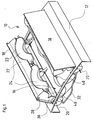
- the holder according to the invention shown in FIG. 1, designated overall by 10 has a box-shaped, flat housing 12 with a curved top.
- the Housing 12 forms a drip pan. It has a rectangular top Opening 16, which can be closed with two lids 18.
- the lid 18 are on the side protruding pivot pin 20, which engage in holes in both sides of the housing 12, pivotally connected to the housing 12.
- Define the pivot pin 20 Pivot axes of the cover 18.
- the pivot axes run parallel to the longitudinal edges the opening 16 and to the longitudinal edges of the cover 18, there is a cover 18 on each Longitudinal edge of the opening 16 of the housing 12 attached.
- the two covers 18 can be moved from an essentially lying position, as they are 3, in a substantially standing position, as shown in Figure 1 and 2 is shown pivot. Close in the essentially lying position the lid 18 the opening 16 of the housing 12. In the substantially standing Position, the two covers 18 are at a distance from each other, which is the setting a beverage container, not shown, such as a beverage can, a mug or a cup.
- the cover 18 form holding elements for in illustrated embodiment two such beverage containers.
- Lid 18 has a longitudinal wall 22, which in the use position in the direction of each other lid 18 protrudes.
- the longitudinal walls 22 each have two circular arcs Recesses 23 on which hold a set beverage container.
- Each of the two covers 18 has a diameter for each of the two recesses 23 a spring-loaded, pivotable pressure flap 24.
- the pressure flaps 24 have laterally projecting pivot pins 26, which in pin holes 28th the lid 18 engage.
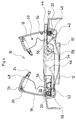
- the covers 18 forming the two holding elements have a coupling gear which is explained below with reference to FIG. 2.
- Figure 2 shows an end view of the holder 10, an end wall of the housing 12 facing the viewer not being shown is so that the coupling gear is visible.
- the coupling gear has a coupling rod 32, which is hung in eyes 34 in end walls 36 of the cover 18.
- the Eyes 34 form swivel joints 34 for the coupling rod 32. These swivel joints 34 are arranged at a distance from the pivot pin 20 about which the cover 18th are pivotable.
- the swivel joints 34 of the coupling rod 32 are on the two Lids 18 on opposite sides of the pivot pins 20 of the lids 18 arranged, the coupling rod 32 engages in the substantially standing position of the Cover 18 on one of the covers 18 above and on the other cover 18 below the Pivot pin 20 on.
- This covers the cover 18 with respect to the pivot pin 20 opposite arrangement of the pivot joints 34 of the coupling rod 32 causes the Coupling rod 32 an opposing pivoting movement of the two covers 18.
- the two Lids 18 are forced to move synchronously with one another through the coupling rod 32 in the essentially lying or vice versa in the essentially standing Position.
- this cover Around the coupling rod 32 in the essentially standing position of the cover 18 one, in the illustrated embodiment on the left cover 18 below the To be able to attach the pivot pin 20, this cover has an extension 38, which extends the cover 18 beyond the pivot pin 20 and in which the Eye 34 is attached, which forms the swivel joint 34 for the coupling rod 32.
- the holder 10 has an opening spring element in the form of a torsion coil spring 40 on.
- One leg of the torsion coil spring 40 is between two retaining cams 42 of the Housing 12 attached.
- the other leg of the torsion coil spring 40 rests an inside of the lid 18 and is held by a retaining cam 44 in contact Cover 18 held.
- the torsion coil spring 40 pivots the cover 18 out of the Essentially lying position in the shown in Figures 1 and 2, essentially standing position. In the position shown in Figures 1 and 2 is the torsion coil spring 40 relaxed, which is why this position of the lid 18 as a neutral Position is called.
- the torsion coil spring pivots via the coupling rod 32 40 also the other cover 18 in the illustrated, essentially neutral standing position.
- the holder 10 has gears for the pressure flaps 24, which the pressure flaps 24 when pivoting the cover 18 in the substantially lying position in the direction of Swing the inside of the lid.
- the gears are designed as cam gears. she have a fixed cam 46 on the inside of the end walls of the housing 12 is attached.
- the pressure flaps 24 have laterally protruding sliding pins 48, which cooperate with the control cams 46. Are the lids 18th pivoted downward into the essentially lying position, the control pins arrive 48 of the pressure flaps 24 in contact with the control cams 46 along which you slide.
- the control pins 48 pivot the pressure flaps 24 against the Force of the torsion coil springs 30 towards the inside of the cover 18. This Swiveling the pressure flaps 24 in the direction of the inside of the cover 18 when Swiveling the cover 18 into the essentially lying position enables one lower overall height of the housing 12.
- FIG. 4 shows a modification of the holder 10.
- the coupling gear is designed as a rack and pinion gear.
- the cover 18 of the holder 10 from FIG. 4 have gear segments 52 which are concentric in an arc extend around the pivot pin 20 of the cover 18. This is where Gear segment 52 of a cover 18 with the cover 18 essentially standing above and the gear segment 52 of the other cover 18 below the pivot pin 20.
- a rack 54 with two oppositely oriented, straight lines Teeth 56 meshes with the gear segments 52 of the two covers 18.
- the rack 54 is slidably guided in the housing 12. By swiveling one Cover 18, the rack 24 is moved and the other cover 18 in opposite directions panned.
- the rack 54 thus, like the coupling rod 32, causes a synchronous Swing the lid 18 into the substantially lying or in the Mainly standing position.
- the holder 10 shown in FIG. 4 is otherwise constructed the same as the holder 10 shown in Figures 1-3 and it is used to avoid of repetitions referred to the corresponding statements.
Landscapes
- Engineering & Computer Science (AREA)
- Physics & Mathematics (AREA)
- Thermal Sciences (AREA)
- Transportation (AREA)
- Mechanical Engineering (AREA)
- Passenger Equipment (AREA)
- Vehicle Step Arrangements And Article Storage (AREA)
- Filling Of Jars Or Cans And Processes For Cleaning And Sealing Jars (AREA)
- Table Equipment (AREA)
Abstract
Description
- Figur 1
- eine perspektivische Darstellung eines erfindungsgemäßen Halters in einer Gebrauchsstellung;
- Figur 2
- eine Stirndarstellung des Halters aus Figur 1;
- Figur 3
- den Halter gemäß Figur 2 in einer Nichtgebrauchsstellung; und
- Figur 4
- eine abgewandelte Ausführungsform des Halters aus Figur 1 in einer Figur 2 entsprechenden Darstellung gemäß der Erfindung.
Claims (9)
- Halter für einen Getränkebehälter, mit zwei Halteelementen (18), die um zwei voneinander beabstandete Schwenkachsen aus einer im Wesentlichen liegenden in eine im Wesentlichen nach oben stehende Stellung und umgekehrt schwenkbar sind, wobei die beiden Halteelemente (18) in ihrer im Wesentlichen stehenden Stellung einen Abstand voneinander aufweisen, der das Einstellen eines Getränkebehälters zwischen die beiden Halteelemente (18) erlaubt, und mit einem Koppelgetriebe (32; 54), welches eine gegenläufige Schwenkbewegung der beiden Halteelemente (18) bewirkt.
- Halter nach Anspruch 1, dadurch gekennzeichnet, dass die Halteelemente (18) als Deckel (18) ausgebildet sind, die in ihrer im Wesentlichen liegenden Stellung eine Öffnung (16) des Halters (10) verschließen.
- Halter nach Anspruch 1, dadurch gekennzeichnet, dass das Koppelgetriebe (32) eine Koppelstange (32) aufweist, die über Schwenkgelenke (34) schwenkbar mit den beiden Halteelementen (18) verbunden ist, wobei die Schwenkgelenke (34) mit Abstand von den Schwenkachsen der Halteelemente (18) an den Halteelementen (18) angeordnet sind, und dass die Schwenkgelenke (34) an den beiden Halteelementen (18) in Bezug auf deren Schwenkachsen auf gegenüberliegenden Seiten angeordnet sind, so dass die Koppelstange (32) die gegenläufige Schwenkbewegung der Halteetemente (18) bewirkt.
- Halter nach Anspruch 1, dadurch gekennzeichnet, dass das Koppelgetriebe (32) als Zahnstangengetriebe (52, 54) ausgebildet ist.
- Halter nach Anspruch 1, dadurch gekennzeichnet, dass der Halter (10) ein Öffnungsfederelement (40) aufweist, welches die beiden Halteelemente (18) in eine neutrale, im Wesentlichen stehende Stellung nach oben schwenkt, dass die Halteelemente (18) gegen die Kraft des Öffnungsfederelements (40) über die neutrale Stellung hinaus auseinanderdrückbar sind, und dass der Halter (10) eine lösbare Verriegelungseinrichtung aufweist, die die Halteelemente (18) gegen die Kraft des Öffnungsfederelements (40) in der im Wesentlichen liegenden Stellung hält.
- Halter nach Anspruch 1, dadurch gekennzeichnet, dass ein Halteelement (18) eine schwenkbare, federbeaufschlagte Andruckklappe (24) aufweist, die einen eingestellten Getränkebehälter in Richtung des anderen Halteelements (18) drückt, und dass der Halter (10) ein Getriebe (46, 48) aufweist, welches beim Schwenken der Halteelemente (18) in die im Wesentlichen liegende Stellung die Andruckklappe (24) in Richtung des Halteelements (18) schwenkt.
- Halter nach Anspruch 6, dadurch gekennzeichnet, dass das Getriebe (46, 48) für die Andruckklappe (24) ein Kurvengetriebe aufweist.
- Halter nach Anspruch 7, dadurch gekennzeichnet, dass das Kurvengetriebe eine ortsfeste Steuerkurve (46) aufweist, an welcher die Andruckklappe (24) selbst oder ein mit ihr verbundenes Steuerelement (48) beim Schwenken der Halteelemente (18) in die im Wesentlichen liegende Stellung entlanggleitet.
- Halter nach Anspruch 2, dadurch gekennzeichnet, dass der Halter (10) ein Gehäuse (12) aufweist, an dem die beiden als Deckel ausgebildeten Halteelemente (18) schwenkbar angebracht sind, dass das Gehäuse (12) eine Öffnung (16) an einer Oberseite aufweist, die die Halteelemente (18) in ihrer im Wesentlichen liegenden Stellung verschließen, und dass das Gehäuse (12) als Auffangwanne für aus einem in den Halter (10) eingestellten Getränkebehälter austretende Flüssigkeit ausgebildet ist.
Applications Claiming Priority (2)
| Application Number | Priority Date | Filing Date | Title |
|---|---|---|---|
| DE19935144A DE19935144A1 (de) | 1999-07-27 | 1999-07-27 | Halter für einen Getränkebehälter |
| DE19935144 | 1999-07-27 |
Publications (3)
| Publication Number | Publication Date |
|---|---|
| EP1093962A2 true EP1093962A2 (de) | 2001-04-25 |
| EP1093962A3 EP1093962A3 (de) | 2002-01-02 |
| EP1093962B1 EP1093962B1 (de) | 2004-04-21 |
Family
ID=7916158
Family Applications (1)
| Application Number | Title | Priority Date | Filing Date |
|---|---|---|---|
| EP00112650A Expired - Lifetime EP1093962B1 (de) | 1999-07-27 | 2000-06-15 | Halter für einen Getränkebehälter |
Country Status (5)
| Country | Link |
|---|---|
| US (1) | US6409136B1 (de) |
| EP (1) | EP1093962B1 (de) |
| AT (1) | ATE264767T1 (de) |
| DE (2) | DE19935144A1 (de) |
| ES (1) | ES2216765T3 (de) |
Cited By (1)
| Publication number | Priority date | Publication date | Assignee | Title |
|---|---|---|---|---|
| CN102431479A (zh) * | 2010-09-29 | 2012-05-02 | 李尔公司 | 具有一对盖和单个释放按钮的杯支架组件 |
Families Citing this family (34)
| Publication number | Priority date | Publication date | Assignee | Title |
|---|---|---|---|---|
| ATE297329T1 (de) * | 2001-04-06 | 2005-06-15 | Neocon Internat Inc | Gepäck-organizer mit hochklappbaren wänden |
| DE50201709D1 (de) * | 2001-05-17 | 2005-01-13 | Jos Weber Gmbh & Co Kg Kunstst | Gefässhalter, insbesondere als Innenausstattung für Fahrzeuge |
| DE10143639A1 (de) * | 2001-09-06 | 2003-03-27 | Fischer Automotive Sys Gmbh | Sektglashalter |
| US6692053B1 (en) * | 2002-01-04 | 2004-02-17 | Johnson Controls Technology Company | Dual purpose storage and holding system |
| JP4011359B2 (ja) * | 2002-02-15 | 2007-11-21 | 株式会社ニフコ | カップホルダ装置 |
| KR100488859B1 (ko) * | 2002-07-24 | 2005-05-11 | 현대자동차주식회사 | 자동차용 컵홀더 |
| US6779769B1 (en) * | 2002-08-14 | 2004-08-24 | Lear Corporation | Multi-purpose holder installed in a vehicle |
| US6695380B1 (en) * | 2003-01-08 | 2004-02-24 | Lear Corporation | Vehicular floor panel |
| US6776381B1 (en) * | 2003-01-30 | 2004-08-17 | Andrew H. Gisch | Cup holder |
| DE20308296U1 (de) * | 2003-05-27 | 2004-10-07 | Fischer Automotive Systems Gmbh | Ablagefach |
| USD515417S1 (en) * | 2003-11-26 | 2006-02-21 | Mark Douglas Haggard | Grooved beverage locking device |
| US20050205590A1 (en) * | 2004-03-17 | 2005-09-22 | Ulf Bastian | Device for holding beverages |
| US7188882B2 (en) * | 2004-04-16 | 2007-03-13 | Lear Corporation | Multi-purpose holder installed in a vehicle |
| US8622469B2 (en) * | 2006-09-14 | 2014-01-07 | Indiana Mills & Manufacturing, Inc. | Apparatus for restraining an object in a vehicle |
| DE102007054488A1 (de) * | 2007-11-15 | 2009-05-20 | Fischer Automotive Systems Gmbh & Co. Kg | Halter für einen Getränkebehälter |
| DE102008006102B4 (de) | 2008-01-25 | 2018-11-08 | Dr. Ing. H.C. F. Porsche Aktiengesellschaft | Behälter zum Einbau in den Innenraum eines Kraftfahrzeuges |
| WO2011109615A2 (en) | 2010-03-03 | 2011-09-09 | Lear Corporation | Armrest assembly having beverage holder |
| JP2012046090A (ja) * | 2010-08-27 | 2012-03-08 | Nifco Inc | カップホルダ |
| DE102011083457B4 (de) * | 2010-09-29 | 2020-03-12 | Lear Corporation | Getränkehalteranordnung mit einem Paar von Deckeln und einer einzelnen Freigabetaste |
| DE102011008581B4 (de) * | 2011-01-14 | 2019-11-28 | Audi Ag | Behälterhalter für einen Fahrzeuginnenraum eines Fahrzeugs zur Aufnahme von Getränkebehältern |
| US8708408B2 (en) | 2011-10-03 | 2014-04-29 | Lear Corporation | Armrest assembly having beverage holder |
| DE102012208275A1 (de) * | 2012-05-16 | 2013-11-21 | Bos Gmbh & Co. Kg | Aufnahmevorrichtung für wenigstens ein Flaschen- oder Becherbehältnis in einem Fahrzeuginnenraum |
| DE102012018175B3 (de) * | 2012-09-14 | 2013-12-12 | Ferdinand Likosar | Universal-Klemmhalter zur Halterung von Gegenständen beliebiger Art |
| JP6106048B2 (ja) * | 2013-08-19 | 2017-03-29 | 株式会社ニフコ | カップホルダ |
| GB2509585A (en) * | 2013-11-06 | 2014-07-09 | Daimler Ag | Storage compartment for an interior of a motor vehicle |
| US9796317B2 (en) * | 2015-06-04 | 2017-10-24 | Ford Global Technologies Llc | Cup holder retention feature |
| US9597991B2 (en) * | 2015-08-07 | 2017-03-21 | GM Global Technology Operations LLC | Emerging bay door cupholder |
| DE102016000909B3 (de) * | 2016-01-29 | 2017-03-16 | Grammer Ag | Deckelvorrichtung, Ablagefach mit Deckelvorrichtung und Werkzeug zur Montage |
| US10189390B2 (en) * | 2016-03-31 | 2019-01-29 | Ford Global Technologies, Llc | Split wing armrest dual pawl latch mechansim |
| JP2022029557A (ja) * | 2020-08-05 | 2022-02-18 | 明和工業株式会社 | 車両用収容物保持装置 |
| JP7524850B2 (ja) | 2021-07-09 | 2024-07-30 | トヨタ紡織株式会社 | カップホルダ |
| KR102867172B1 (ko) * | 2023-04-05 | 2025-10-01 | 현대트랜시스 주식회사 | 반자동 컵홀더 |
| DE102024122292B4 (de) * | 2024-08-05 | 2026-02-19 | Audi Aktiengesellschaft | Behälterhalter für ein Fahrzeug |
| DE102024122291B4 (de) * | 2024-08-05 | 2026-02-19 | Audi Aktiengesellschaft | Behälterhalter für ein Fahrzeug |
Family Cites Families (6)
| Publication number | Priority date | Publication date | Assignee | Title |
|---|---|---|---|---|
| DE4200823A1 (de) * | 1992-01-15 | 1993-07-22 | Bayerische Motoren Werke Ag | Gefaesshalter |
| DE4306935C1 (de) * | 1993-03-05 | 1994-07-07 | Audi Ag | Haltevorrichtung für ein Getränkebehältnis |
| DE9306415U1 (de) * | 1993-04-28 | 1994-09-08 | Paulmann & Crone GmbH & Co KG, 58511 Lüdenscheid | Vorrichtung zur Halterung von Getränkedosen |
| US5505516A (en) * | 1994-03-15 | 1996-04-09 | Prince Corporation | Compact container holder |
| JPH082308A (ja) | 1994-06-24 | 1996-01-09 | Ikeda Bussan Co Ltd | 車両用アームレスト |
| DE29810872U1 (de) * | 1998-06-17 | 1998-08-13 | Sarnatech Paulmann & Crone GmbH, 58511 Lüdenscheid | Vorrichtung für Kraftfahrzeuge zum Haltern von Getränkebehältern |
-
1999
- 1999-07-27 DE DE19935144A patent/DE19935144A1/de not_active Withdrawn
-
2000
- 2000-06-15 DE DE50006133T patent/DE50006133D1/de not_active Expired - Fee Related
- 2000-06-15 EP EP00112650A patent/EP1093962B1/de not_active Expired - Lifetime
- 2000-06-15 ES ES00112650T patent/ES2216765T3/es not_active Expired - Lifetime
- 2000-06-15 AT AT00112650T patent/ATE264767T1/de not_active IP Right Cessation
- 2000-07-26 US US09/625,716 patent/US6409136B1/en not_active Expired - Fee Related
Non-Patent Citations (1)
| Title |
|---|
| None |
Cited By (2)
| Publication number | Priority date | Publication date | Assignee | Title |
|---|---|---|---|---|
| CN102431479A (zh) * | 2010-09-29 | 2012-05-02 | 李尔公司 | 具有一对盖和单个释放按钮的杯支架组件 |
| CN102431479B (zh) * | 2010-09-29 | 2016-01-20 | 李尔公司 | 具有一对盖和单个释放按钮的杯支架组件 |
Also Published As
| Publication number | Publication date |
|---|---|
| EP1093962B1 (de) | 2004-04-21 |
| US6409136B1 (en) | 2002-06-25 |
| EP1093962A3 (de) | 2002-01-02 |
| ES2216765T3 (es) | 2004-11-01 |
| DE50006133D1 (de) | 2004-05-27 |
| DE19935144A1 (de) | 2001-02-01 |
| ATE264767T1 (de) | 2004-05-15 |
Similar Documents
| Publication | Publication Date | Title |
|---|---|---|
| EP1093962B1 (de) | Halter für einen Getränkebehälter | |
| EP1059198B1 (de) | Haltevorrichtung für einen Getränkebehälter | |
| DE4404078A1 (de) | Vorrichtung zum Halten von Getränkebehältern, Trinkgefäßen oder dergleichen | |
| DE202007006689U1 (de) | Antriebseinrichtung für einen Beschlag | |
| EP1316472A1 (de) | Halter für einen Getränkebehälter | |
| DE19944817A1 (de) | Haltevorrichtung für einen Getränkebehälter | |
| EP1033282A2 (de) | Haltevorrichtung für einen Getränkebehälter in einem Kraftwagen | |
| DE4437244A1 (de) | Verschwenkbare Armlehne für einen Omnibussitz sowie Omnibussitz ausgestattet mit einer solchen Armlehne | |
| DE10356288B4 (de) | Röntgendetektorlade | |
| DE202005006077U1 (de) | Becherhalter | |
| DE102005039266B4 (de) | Vorrichtung zum Halten von Getränkedosen, Trinkflaschen und ähnlichen Behältnissen | |
| DE20204882U1 (de) | Halter für einen Getränkebehälter | |
| EP1099596A2 (de) | Haltevorrichtung für einen Getränkebehälter | |
| DE19845930A1 (de) | Becherhalteranordnung für ein Kraftfahrzeug | |
| EP1281567A2 (de) | Getränkehalter | |
| DE19963202A1 (de) | Halterungsvorrichtung für Gefäße in Kraftfahrzeugen | |
| EP1972492B1 (de) | Halter für einen Getränkebehälter | |
| EP0358894A2 (de) | Vorrichtung zum Vorwählen und Schalten eines Kraftfahrzeug-Gangschaltgetriebes | |
| EP1238854B1 (de) | Halterungsvorrichtung für Trinkgefässe in Kraftfahrzeugen | |
| DE2529556A1 (de) | Vorrichtung zur einstellung eines fahrzeugsitzes | |
| DE19956649A1 (de) | Halter für einen Getränkebehälter in einem Kraftwagen | |
| DE202010010115U1 (de) | Mechanik für einen Bürostuhl | |
| EP0578072B1 (de) | Vorrichtung zum Halten einer Anhänge-Kupplungs-Tragplatte | |
| EP3572056B1 (de) | Tragenlagerungseinrichtung | |
| DE19924226C2 (de) | Ausstattungsteil für Kraftfahrzeuge |
Legal Events
| Date | Code | Title | Description |
|---|---|---|---|
| PUAI | Public reference made under article 153(3) epc to a published international application that has entered the european phase |
Free format text: ORIGINAL CODE: 0009012 |
|
| AK | Designated contracting states |
Kind code of ref document: A2 Designated state(s): AT BE CH CY DE DK ES FI FR GB GR IE IT LI LU MC NL PT SE |
|
| AX | Request for extension of the european patent |
Free format text: AL;LT;LV;MK;RO;SI |
|
| PUAL | Search report despatched |
Free format text: ORIGINAL CODE: 0009013 |
|
| AK | Designated contracting states |
Kind code of ref document: A3 Designated state(s): AT BE CH CY DE DK ES FI FR GB GR IE IT LI LU MC NL PT SE |
|
| AX | Request for extension of the european patent |
Free format text: AL;LT;LV;MK;RO;SI |
|
| 17P | Request for examination filed |
Effective date: 20020328 |
|
| AKX | Designation fees paid |
Free format text: AT BE CH CY DE DK ES FI FR GB GR IE IT LI LU MC NL PT SE |
|
| 17Q | First examination report despatched |
Effective date: 20021018 |
|
| GRAP | Despatch of communication of intention to grant a patent |
Free format text: ORIGINAL CODE: EPIDOSNIGR1 |
|
| GRAS | Grant fee paid |
Free format text: ORIGINAL CODE: EPIDOSNIGR3 |
|
| GRAA | (expected) grant |
Free format text: ORIGINAL CODE: 0009210 |
|
| AK | Designated contracting states |
Kind code of ref document: B1 Designated state(s): AT BE CH CY DE DK ES FI FR GB GR IE IT LI LU MC NL PT SE |
|
| PG25 | Lapsed in a contracting state [announced via postgrant information from national office to epo] |
Ref country code: IE Free format text: LAPSE BECAUSE OF FAILURE TO SUBMIT A TRANSLATION OF THE DESCRIPTION OR TO PAY THE FEE WITHIN THE PRESCRIBED TIME-LIMIT Effective date: 20040421 Ref country code: CY Free format text: LAPSE BECAUSE OF FAILURE TO SUBMIT A TRANSLATION OF THE DESCRIPTION OR TO PAY THE FEE WITHIN THE PRESCRIBED TIME-LIMIT Effective date: 20040421 Ref country code: FI Free format text: LAPSE BECAUSE OF FAILURE TO SUBMIT A TRANSLATION OF THE DESCRIPTION OR TO PAY THE FEE WITHIN THE PRESCRIBED TIME-LIMIT Effective date: 20040421 |
|
| REG | Reference to a national code |
Ref country code: GB Ref legal event code: FG4D Free format text: NOT ENGLISH |
|
| REG | Reference to a national code |
Ref country code: SE Ref legal event code: TRGR |
|
| PGFP | Annual fee paid to national office [announced via postgrant information from national office to epo] |
Ref country code: FR Payment date: 20040429 Year of fee payment: 5 |
|
| REG | Reference to a national code |
Ref country code: CH Ref legal event code: EP |
|
| REG | Reference to a national code |
Ref country code: IE Ref legal event code: FG4D Free format text: GERMAN |
|
| REF | Corresponds to: |
Ref document number: 50006133 Country of ref document: DE Date of ref document: 20040527 Kind code of ref document: P |
|
| PGFP | Annual fee paid to national office [announced via postgrant information from national office to epo] |
Ref country code: ES Payment date: 20040607 Year of fee payment: 5 |
|
| PGFP | Annual fee paid to national office [announced via postgrant information from national office to epo] |
Ref country code: GB Payment date: 20040609 Year of fee payment: 5 |
|
| PG25 | Lapsed in a contracting state [announced via postgrant information from national office to epo] |
Ref country code: LU Free format text: LAPSE BECAUSE OF NON-PAYMENT OF DUE FEES Effective date: 20040615 Ref country code: AT Free format text: LAPSE BECAUSE OF NON-PAYMENT OF DUE FEES Effective date: 20040615 |
|
| PGFP | Annual fee paid to national office [announced via postgrant information from national office to epo] |
Ref country code: SE Payment date: 20040616 Year of fee payment: 5 |
|
| PGFP | Annual fee paid to national office [announced via postgrant information from national office to epo] |
Ref country code: NL Payment date: 20040629 Year of fee payment: 5 |
|
| PG25 | Lapsed in a contracting state [announced via postgrant information from national office to epo] |
Ref country code: MC Free format text: LAPSE BECAUSE OF NON-PAYMENT OF DUE FEES Effective date: 20040630 Ref country code: LI Free format text: LAPSE BECAUSE OF NON-PAYMENT OF DUE FEES Effective date: 20040630 Ref country code: CH Free format text: LAPSE BECAUSE OF NON-PAYMENT OF DUE FEES Effective date: 20040630 Ref country code: BE Free format text: LAPSE BECAUSE OF NON-PAYMENT OF DUE FEES Effective date: 20040630 |
|
| PG25 | Lapsed in a contracting state [announced via postgrant information from national office to epo] |
Ref country code: DK Free format text: LAPSE BECAUSE OF FAILURE TO SUBMIT A TRANSLATION OF THE DESCRIPTION OR TO PAY THE FEE WITHIN THE PRESCRIBED TIME-LIMIT Effective date: 20040721 Ref country code: GR Free format text: LAPSE BECAUSE OF FAILURE TO SUBMIT A TRANSLATION OF THE DESCRIPTION OR TO PAY THE FEE WITHIN THE PRESCRIBED TIME-LIMIT Effective date: 20040721 |
|
| GBT | Gb: translation of ep patent filed (gb section 77(6)(a)/1977) |
Effective date: 20040809 |
|
| ET | Fr: translation filed | ||
| REG | Reference to a national code |
Ref country code: ES Ref legal event code: FG2A Ref document number: 2216765 Country of ref document: ES Kind code of ref document: T3 |
|
| REG | Reference to a national code |
Ref country code: IE Ref legal event code: FD4D |
|
| BERE | Be: lapsed |
Owner name: LAND ROVER GROUP LTD Effective date: 20040630 Owner name: FISCHERWERKE ARTUR FISCHER G.M.B.H. & CO. KG Effective date: 20040630 |
|
| REG | Reference to a national code |
Ref country code: CH Ref legal event code: PL |
|
| PLBE | No opposition filed within time limit |
Free format text: ORIGINAL CODE: 0009261 |
|
| STAA | Information on the status of an ep patent application or granted ep patent |
Free format text: STATUS: NO OPPOSITION FILED WITHIN TIME LIMIT |
|
| 26N | No opposition filed |
Effective date: 20050124 |
|
| PG25 | Lapsed in a contracting state [announced via postgrant information from national office to epo] |
Ref country code: IT Free format text: LAPSE BECAUSE OF NON-PAYMENT OF DUE FEES;WARNING: LAPSES OF ITALIAN PATENTS WITH EFFECTIVE DATE BEFORE 2007 MAY HAVE OCCURRED AT ANY TIME BEFORE 2007. THE CORRECT EFFECTIVE DATE MAY BE DIFFERENT FROM THE ONE RECORDED. Effective date: 20050615 Ref country code: GB Free format text: LAPSE BECAUSE OF NON-PAYMENT OF DUE FEES Effective date: 20050615 |
|
| PG25 | Lapsed in a contracting state [announced via postgrant information from national office to epo] |
Ref country code: SE Free format text: LAPSE BECAUSE OF NON-PAYMENT OF DUE FEES Effective date: 20050616 Ref country code: ES Free format text: LAPSE BECAUSE OF NON-PAYMENT OF DUE FEES Effective date: 20050616 |
|
| PG25 | Lapsed in a contracting state [announced via postgrant information from national office to epo] |
Ref country code: NL Free format text: LAPSE BECAUSE OF NON-PAYMENT OF DUE FEES Effective date: 20060101 |
|
| EUG | Se: european patent has lapsed | ||
| PG25 | Lapsed in a contracting state [announced via postgrant information from national office to epo] |
Ref country code: FR Free format text: LAPSE BECAUSE OF NON-PAYMENT OF DUE FEES Effective date: 20060228 |
|
| GBPC | Gb: european patent ceased through non-payment of renewal fee |
Effective date: 20050615 |
|
| NLV4 | Nl: lapsed or anulled due to non-payment of the annual fee |
Effective date: 20060101 |
|
| REG | Reference to a national code |
Ref country code: FR Ref legal event code: ST Effective date: 20060228 |
|
| REG | Reference to a national code |
Ref country code: ES Ref legal event code: FD2A Effective date: 20050616 |
|
| PG25 | Lapsed in a contracting state [announced via postgrant information from national office to epo] |
Ref country code: PT Free format text: LAPSE BECAUSE OF NON-PAYMENT OF DUE FEES Effective date: 20040921 |
|
| PGFP | Annual fee paid to national office [announced via postgrant information from national office to epo] |
Ref country code: DE Payment date: 20080630 Year of fee payment: 9 |
|
| PG25 | Lapsed in a contracting state [announced via postgrant information from national office to epo] |
Ref country code: DE Free format text: LAPSE BECAUSE OF NON-PAYMENT OF DUE FEES Effective date: 20100101 |