EP1093998A2 - Verfahren zur Rettung einer über Bord gefallenen Person, Rettungseinrichtung und Vorrichtung zum Halten eines Signalmittels - Google Patents
Verfahren zur Rettung einer über Bord gefallenen Person, Rettungseinrichtung und Vorrichtung zum Halten eines Signalmittels Download PDFInfo
- Publication number
- EP1093998A2 EP1093998A2 EP00122807A EP00122807A EP1093998A2 EP 1093998 A2 EP1093998 A2 EP 1093998A2 EP 00122807 A EP00122807 A EP 00122807A EP 00122807 A EP00122807 A EP 00122807A EP 1093998 A2 EP1093998 A2 EP 1093998A2
- Authority
- EP
- European Patent Office
- Prior art keywords
- signaling
- holding
- signaling means
- locking
- holder
- Prior art date
- Legal status (The legal status is an assumption and is not a legal conclusion. Google has not performed a legal analysis and makes no representation as to the accuracy of the status listed.)
- Granted
Links
Images


Classifications
-
- B—PERFORMING OPERATIONS; TRANSPORTING
- B63—SHIPS OR OTHER WATERBORNE VESSELS; RELATED EQUIPMENT
- B63C—LAUNCHING, HAULING-OUT, OR DRY-DOCKING OF VESSELS; LIFE-SAVING IN WATER; EQUIPMENT FOR DWELLING OR WORKING UNDER WATER; MEANS FOR SALVAGING OR SEARCHING FOR UNDERWATER OBJECTS
- B63C9/00—Life-saving in water
- B63C9/0005—Life-saving in water by means of alarm devices for persons falling into the water, e.g. by signalling, by controlling the propulsion or manoeuvring means of the boat
-
- B—PERFORMING OPERATIONS; TRANSPORTING
- B63—SHIPS OR OTHER WATERBORNE VESSELS; RELATED EQUIPMENT
- B63C—LAUNCHING, HAULING-OUT, OR DRY-DOCKING OF VESSELS; LIFE-SAVING IN WATER; EQUIPMENT FOR DWELLING OR WORKING UNDER WATER; MEANS FOR SALVAGING OR SEARCHING FOR UNDERWATER OBJECTS
- B63C9/00—Life-saving in water
- B63C9/22—Devices for holding or launching life-buoys, inflatable life-rafts, or other floatable life-saving equipment
Definitions
- the invention relates to a method for saving an over Board fallen person according to the preamble of the claim 1, a rescue system according to the preamble of Claim 2 and a device for holding a Signaling means according to the preamble of claim 4.
- Floatable signaling means can be provided which Ejecting the rescue equipment can be activated. Special measures are required to make the signal means simple and safe way of using the rescue equipment from a suitable bracket to release and activate.
- the object of the present invention is a method and to create a rescue device or a device with which is a signaling device that is simple and reliable when needed Rescue equipment is detachable from its holder. That too should Signal means can be reliably fixed until triggered. After all, the signaling means should be able to be activated at an early stage.
- the object is characterized by the features of Claim 1 solved.
- the lifeline thrown overboard first actuates a locking means in the sense of a Deactivation.
- This locking device is with the life-saving device and connected to a holder of the signaling means.
- deactivating the locking means the Open the holder of the signaling device and then the Signal means are pulled out of the holder.
- this is in the holder when not in use stored signaling means with the rescue means by a traction means connected.
- Locking means of the bracket arranged such that at a train originating from the rescue equipment on the traction device first the locking means to release the bracket actuated and then the signaling device from the holder is extractable.
- connection of the rescue equipment with the signaling means and the locking means such that also the signal means from the traction means from the holder can be pulled out after the pulling device actuation of the locking means.
- the signaling means of a holder having a retaining collar fixed includes at least a portion of the signaling means Completely.
- the collar is at least from two by a releasable locking means or a closure holding collar parts formed together.
- a signaling means can be light, smoke, sound and / or radio signals submit. To achieve a stable position on the water surface the signaling means is usually rod-shaped clear focus on one of two opposing Ends formed. Due to the longitudinal extension of the A longitudinal axis of the same is defined by means of the signal.
- the collar comprises the signaling means in a plane transverse to its longitudinal axis completely.
- the holding collar is preferably located on an outer circumference of the signaling means this.
- the retaining collar parts are closed by a closure Locking means held together. Accordingly, is a Bend up the retaining collar parts only in connection with one The lock can be released.
- the signal means form-fitting and not only clamping as in the prior art held.
- the holder or the holding collar can also only be a Include or hold part of the signaling means, for example one for this purpose, a tab formed on the signaling means Cone, ring or the like.
- the clasp is formed by a special design of the Retaining collar parts in connection with a locking device.
- So-called Retaining collar ends - as ends of the retaining collar parts - are claw-like design.
- One end of the collar has several End claws that define a claw plane through which at least a claw of the other end of the collar in closed state of the holding member passes and with a blocking element against a backward movement by the Claw plane is secured through.
- To close the holding device must first cross the claw through the claw level be moved through. This creates a gap about a gap between the end claws of one end of the retaining collar on the one hand and the at least one counterclaw of the other end of the collar on the other hand, in the (in the gap) the locking member can be used.
- For a backward movement of the Counterclaw through the claw level must therefore first Blocking organ to be removed. The blocking organ itself takes place during blocking the claws only compressive forces.
- Counter claw pin and recess on Blocking device are dimensioned and matched to one another, that the blocking organ can only be overcome by defined clamping or frictional force deducted from the pin can be.
- a material destructive is also possible Fuse.
- the pin and / or locking device are dimensioned so that that removal of the blocking organ by a defined force while destroying the pin and / or the Blocking organ is possible.
- the signaling means is advantageously flexible Traction means, especially a line with a life-saving device connected.
- the traction means is connected to the locking member, in particular such that a pull on the traction device initially the blocking element triggers and then the signaling means released the bracket pulls.
- the signal means is thus automatic by pulling the line connected to the life-saving equipment out of the Bracket released.
- the frame can be spaced from the retaining collar parts, have an additional holder, in particular below it, with which another section or other part of the Signal means is held or supported.
- Preferably supports or the additional holder fixes a lower end of the signaling means and is in particular like a pan or Fork formed with a circumferential wall in which the lower end of the signal means is inserted appropriately.
- the Signal means is thus on the additional holder during the Retaining collar the signal means against forces in the direction transverse to Longitudinal axis secures.
- Additional holder and holding collar preferably form together the bracket.
- the additional holder is advantageously movable, in particular arranged pivotably, such that the signaling means the collar is movable while it is still from Additional holder is held or supported.
- the signaling device is at rest with its lower end in the pan.
- the additional holder is in correspondingly movable. With further train action on the signaling means is finally from the additional holder pulled out.
- Switching means for switching on the Signal means provided after or upon acceptance of the same. It is advantageous to have a reed switch on the signaling means a reed contact, e.g. a permanent magnet on the device, is particularly operable on the frame. Other non-contact or without electrical contacts between the device and switching means using signaling means are conceivable.
- the combination of reed switch and reed contact is special functionally reliable, because for the switching process the removal of the Signal means from the device is sufficient.
- a frame supporting the bracket has at its upper end the holding collar and at its lower end the additional holder on.
- the frame is between the holding collar and the additional holder a support for a corresponding area of the signaling means - about a circumferential thickening - provided.
- the reed contact is preferably arranged in the area of the support.
- the invention is not only the device for Holding the signaling means, but also a combination of Signal means and device or a combination of Rescue equipment, signaling devices and devices.
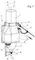
- a signaling means 10 - for example a light smoke signal as a marker for lifebuoys - is in a special device held here from a frame 11, a holding collar 12th and an additional holder 13. Retaining collar 12 and Additional holders 13 together form a holder for the signaling means 10th
- the signaling means 10 is inserted upside down in the holder, namely with a tip 14 pointing downwards. Corresponding has a bottom 15 upwards. Between tip 14 and bottom 15 extends the signaling means 10 with an elongated, almost rotationally symmetrical shape. An imaginary longitudinal axis is included 16 designated. Seen from the bottom 15 is first a round rod-shaped area 17 available. This closes Extension of diameter a conical region 18, which in passes over a wide range 19. The latter closes a circumferential, inward-looking paragraph 20 a domed or conical region 21, which ends with the tip 14. The areas 17 and 21 have approximately the same diameter on, while areas 18 and 19, on the other hand, clearly are wider.
- the frame 11, see in particular Fig. 4, has a flat, multi-curved rod 22, which is also in different Areas is divided.
- the holding collar 12 At an upright upper end 23 the holding collar 12 is arranged. Starting from this the upper end 23, the rod 22 initially runs approximately horizontally (away from the holding collar 12), then after a bend 24 vertically down along a mounting section 25 up to a bend 26, from there again approximately horizontally in Direction to the signaling means 10 and forming a Edition 27. Finally, edition 27 is followed by a downward-facing one Area 28, which also has a lower end 29 having.
- the free end 31 of the Additional holder 13 carries the latter from an upward Position in an obliquely downward position is bendable.
- the strut 30 is provided with a bore 32 which receives an axis 33.
- the strut 30 is functional Part of the additional holder 13.
- Around the axis 33 is a circumferential wall 34 having holding pan 35 pivotable, which receives the tip 14.
- the axis 33 is transverse to Longitudinal axis 16 aligned.
- the fastening area 25 forms between the bends 24 and 26 a recess for the wider areas 18, 19 of the Signal means 10.
- the circulating paragraph 20 of the signaling means 10 on the support 27 at least indirectly lie.
- the holding collar 12 is designed in a special way. This has two opposing, partially annular retaining collar parts 36, 37 on a common crosspiece 38 are connected to the upper end 23 of the frame 11.
- the crosspiece 38 each have the opposite Retaining collar parts 36, 37 retaining collar ends 39, 40. All in all form the cross piece 38, the two retaining collar parts 36, 37 and the continuations - the retaining collar ends 39, 40 - one closed ring 41, which is openable. For this are the Retaining collar ends 39, 40 can be angled transversely to the longitudinal axis 16. Correspondingly, there is a joint 42 between the holding collar part 37 and the associated holding collar end 39. In analog The retaining collar part 36 and the retaining collar end 40 are fashionable connected to each other via a joint 43.
- the collar ends 39, 40 each have claws, the Retaining collar end 40 two claws defining a claw plane 43 44, 45 and the holding collar end 39 a counterclaw 46. While the retaining collar parts 36, 37 and their retaining collar ends 39, 40 run approximately along the shape of the ring 41, are the Claws 40, 45, 46 are arranged transversely, that is to say radially.
- the claws 44, 45 have a slot 47 between them, over a short distance in the area of the end of the collar 40 continues. This corresponds to this Retaining collar end 39 on a very narrow area 48, the after Angling outwards into the mating claw 46.
- the narrow area 48 is dimensioned such that it fits into the slot 47 can occur.
- the counter claw 46 In the closed state (Fig. 3, ring 41) the counter claw 46 has passed through the claw plane 43 forming a gap 49 between the counter claw 46 and the claw plane 43, see FIG. 6.
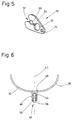
- a key 50 is inserted into the gap 49 as a blocking element, which is shown in Fig. 5 alone.
- the key 50 is one flat, V-shaped disc with a bore 51 at the tip end and a slot 52 at the opposite end.
- the slot 52 initially narrows from its inlet side in a funnel shape, then widens to a round first recess 53, forms a narrow slot section 54 and then leaves again in a second round recess 55.
- the counter claw 46 is assigned a protruding on one side Pin 56 in the closed ring position shown in FIG. 3 passes the gap 49 across and into the gap plane 43 stretched in, see again Fig. 6.
- the slot 52 and the first recess 53 are dimensioned so that in the closed ring position shown in FIG. 3 Sliding the key 50 onto the pin 56 is possible. This is due to the spring properties of the material of the Key 50 to turn off.
- the first recess 53 is said to open the pin 56 that pulling the key 50 from the pin 56 is possible with a certain force.
- the key 50 can be of various types Positions are subtracted from pin 56.
- the signaling means 10 is held by the holding collar 12 held against forces transverse to the longitudinal axis 16 in round rod-shaped area 17 above the wider areas 18, 19.
- the main load of the signaling means rests on the additional holder 13.
- paragraph 20 or another part of the signaling means 10 on the support 27 be supported indirectly or directly.
- the signaling means 10 has a special switching means Mistake.
- this is a reed switch (not shown) which is under the surface of the revolving Paragraph 20 is arranged in a frame 11 facing area.
- the frame 11 corresponds to this provided with a so-called reed contact 58 in Area of the edition 27.
- the reed switch moves away from the reed contact 58 and the signaling means 10 is activated.
- Fig. 2 shows the entire device with frame 11, bracket and signaling means shortly after the key 50 has been released a jerk on the connecting line 57 - about that Deployment of the lifebuoy connected to the leash - was the key 50 from the gap 49 between the claws 44, 45 pulled out on the one hand and the counter claw 46 on the other hand.
- the also with the signaling means 10 slightly below the Retaining collar 12 connected connecting line 57 (line branch 59) now pulls the signaling means 10 against the holding collar ends 39, 40.
- the latter are from the adjacent round rod Area 17 pressed apart so that the signal means 10 um the axis 33 can pivot out of the retaining collar 12. there the signaling device is activated (if necessary in connection with a delay circuit).
- Figures 1 and 2 is the traction device - the connecting line 57 - shown divided, namely with the linen branch 59.
- the linen branch 59 can also be attached to the key 50, for example in a specially designed hole or in a the connecting line 57 receiving bore.
- another Embodiment is provided only a leash that on Signal means is struck and at the same time by a Bore of the key 50 is pulled through.
- one Section of the connecting line between the key 50 and the signal means sags or is not energized is the connecting line with one of the subsections mentioned limiting knot, which prevents the Lanyard prevented by drilling the key 50 and the described chronological order when solving the Key and removing the signaling device.
- the Branch is secured with a knot or the like, so that the aspect ratios do not change under tension and when pulling on the connecting line, first the locking means is solved.
- the frame 11 is, for example, on part of the railing attached to a ship, such as on the bridge of a ship or on the pushpit of a sailing boat.
- the Fastening area 25 laterally notches or similar recesses on, in the clamps, brackets or other connecting means can intervene between frame and railing and one Secure the defined position of the frame 11.
Landscapes
- Engineering & Computer Science (AREA)
- Mechanical Engineering (AREA)
- Ocean & Marine Engineering (AREA)
- Emergency Lowering Means (AREA)
- Motorcycle And Bicycle Frame (AREA)
- Catching Or Destruction (AREA)
Abstract
Description
- Fig. 1
- eine erfindungsgemäße Vorrichtung mit eingesetztem Signalmittel in perspektivischer Darstellung,
- Fig. 2
- die Vorrichtung gemäß Fig. 1 während des Lösens des Signalmittels,
- Fig. 3
- die Vorrichtung gemäß Fig. 1 in geschlossener Position, jedoch ohne Signalmittel,
- Fig. 4
- die Vorrichtung gemäß Fig. 3 in geöffneter Position, analog Fig. 2,
- Fig. 5
- ein Sperrorgan (Schlüssel) für einen Haltekragen in perspektivischer Darstellung,
- Fig. 6
- Haltekragenteile in geschlossener Position mit eingesetztem Sperrorgan in einer Ansicht von oben.
- 10
- Signalmittel
- 11
- Gestell
- 12
- Haltekragen
- 13
- Zusatzhalter
- 14
- Spitze
- 15
- Boden
- 16
- Längsachse
- 17
- Bereich (rundstabförmig)
- 18
- Bereich (konisch)
- 19
- Bereich (breit)
- 20
- Absatz
- 21
- Bereich (gewölbt/konisch)
- 22
- flacher Stab
- 23
- oberes Ende
- 24
- Abwinkelung
- 25
- Befestigungs-Bereich
- 26
- Abwinkelung
- 27
- Auflage
- 28
- Bereich (abwärtsgerichtet)
- 29
- unteres Ende
- 30
- Strebe
- 31
- freies Ende
- 32
- Bohrung
- 33
- Achse
- 34
- umlaufende Wandung
- 35
- Haltepfanne
- 36
- Haltekragenteil
- 37
- Haltekragenteil
- 38
- Querstück
- 39
- Haltekragenende
- 40
- Haltekragenende
- 41
- Ring
- 42
- Gelenk
- 43
- Klauenebene
- 44
- Klaue
- 45
- Klaue
- 46
- Gegenklaue
- 47
- Schlitz
- 48
- schmaler Bereich
- 49
- Spalt
- 50
- Schlüssel (Sperrorgan)
- 51
- Bohrung
- 52
- Schlitz
- 53
- erste Ausnehmung
- 54
- Schlitzabschnitt
- 55
- zweite Ausnehmung
- 56
- Stift
- 57
- Verbindungsleine
- 58
- Reed-Kontakt
- 59
- Leinenzweig
- 60
- Lampen
Claims (18)
- Verfahren zur Rettung einer über Bord gefallenen Person, wobei ein Rettungsmittel, insbesondere ein Rettungsring oder dergleichen, zusammen mit einem mit dem Rettungsmittel verbundenen Signalmittel der über Bord gegangenen Person hinterhergeworfen wird, dadurch gekennzeichnet, dass das Rettungsmittel zusätzlich mit einem Arretierungsmittel einer Halterung des Signalmittels verbunden ist, wobei vom über Bord geworfenen Rettungsmittel zunächst das Arretierungsmittel im Sinne einer Deaktivierung betätigt und anschließend das Signalmittel aus der Halterung herausgezogen wird.
- Rettungseinrichtung, insbesondere an Bord von Schiffen, mit einem Rettungsmittel und einem damit durch ein Zugmittel, vorzugsweise eine Leine, verbundenen Signalmittel, das bei Nichtgebrauch in einer Halterung gelagert ist, dadurch gekennzeichnet, dass an dem Zugmittel zwischen dem Rettungsmittel und dem Signalmittel ein Arretierungsmittel der Halterung derart angeordnet ist, dass bei einer vom Rettungsmittel ausgehenden Straffung des Zugmittels zuerst das Arretierungsmittel zum Freigeben der Halterung betätigbar und danach das Signalmittel aus der Halterung herausziehbar ist.
- Rettungseinrichtung nach Anspruch 2, dadurch gekennzeichnet, dass die Verbindung des Rettungsmittels mit dem Signalmittel und dem Arretierungsmittel derart ist, dass erst nach der über das Zugmittel erfolgenden Betätigung des Arretierungsmittels das Signalmittel von dem Zugmittel aus der Halterung herausziehbar ist.
- Vorrichtung zum Halten eines Signalmittels (10), insbesondere an Bord von Schiffen, mit mindestens einer das Signalmittel (10) fixierenden Halterung, dadurch gekennzeichnet, dass die Halterung mindestens zwei Halteteile aufweist, die durch ein lösbares Arretierungsmittel zusammenhaltbar sind.
- Vorrichtung nach Anspruch 4, dadurch gekennzeichnet, dass die Halteteile (36, 37) Teile eines Haltekragens (12) sind, der mindestens einen Abschnitt (17) des Signalmittels (10) oder ein dem Signalmittel (10) zugeordnetes Teil vollständig umgreift, insbesondere das Signalmittel (10) in einer Ebene quer zu seiner Längsachse (16) von dem Haltekragen (12) vollständig umfasst wird.
- Vorrichtung nach Anspruch 4 oder 5, gekennzeichnet durch ein Gestell (11), an dem die Haltekragenteile (36, 37), insbesondere in einer Ebene quer zur Längsrichtung (16) des Signalmittels (10), angeordnet sind.
- Vorrichtung nach Anspruch 6, dadurch gekennzeichnet, dass die Haltekragenteile (36, 37) bzw. zumindest Teile hiervon auseinanderbewegbar sind und hierzu insbesondere Haltekragenenden (39, 40) relativ zu den Haltekragenteilen im Übrigen abklappbar sind.
- Vorrichtung nach einem oder mehreren der Ansprüche 4 bis 7, dadurch gekennzeichnet, dass das Arretierungsmittel, insbesondere ein Verschluss, für die Haltekragenteile (36, 37) durch Ineinandergreifen und insbesondere formschlüssiges Blockieren einer Bewegung der Haltekragenenden (39, 40) gebildet ist.
- Vorrichtung nach Anspruch 8, dadurch gekennzeichnet, dass ein Haltekragenende (40) mehrere Endklauen (44, 45) aufweist, die eine Klauenebene (43) definieren, durch die mindestens eine Gegenklaue (46) des anderen Haltekragenendes (39) im geschlossenen Zustand des Halteorgans hindurchtritt und mit einem Sperrorgan (Schlüssel 50) als Element des Arretierungsmittels gegen eine Rückwärtsbewegung durch die Klauenebene (43) hindurch gesichert ist.
- Vorrichtung nach Anspruch 9, dadurch gekennzeichnet, dass das Sperrorgan (Schlüssel 50) ein eine Ausnehmung, insbesondere einen Schlitz (52) aufweisendes scheibenförmiges Organ ist, das im geschlossenen Zustand des Halteorgans zwischen den Endklauen (44, 45) einerseits und der Gegenklaue (46) andererseits gehalten ist, und dass das Sperrorgan durch ein in die Ausnehmung (Schlitz 52) tretendes Sicherungsorgan gehalten ist, insbesondere durch einen an einer der Klauen angeordneten Stift (56), vorzugsweise an der Gegenklaue (46).
- Vorrichtung nach Anspruch 10, dadurch gekennzeichnet, dass Ausnehmung (Schlitz 52) und Sicherungsorgan (Stift 56) hinsichtlich ihrer jeweiligen Größe und Festigkeit aufeinander abgestimmt sind, derart, dass ein Zug am Sperrorgan, insbesondere etwa parallel zur Klauenebene (43), mit mehr als einer bestimmten Kraft möglich ist, wobei dann das Sicherungsorgan (Stift 56) aus der Ausnehmung (Schlitz 52) heraustritt oder sogar zum Passieren der Ausnehmung zerstört wird bzw. abreißt.
- Vorrichtung nach einem oder mehreren der Ansprüche 9 bis 11, dadurch gekennzeichnet, dass das Signalmittel (10) über ein flexibles Zugmittel, insbesondere eine Verbindungsleine (57), mit einem Rettungsmittel verbindbar ist, und dass das Zugmittel außerdem mit dem Sperrorgan verbunden ist, insbesondere derart, dass ein Zug an dem Zugmittel zunächst das Sperrorgan löst und dann das freiwerdende Signalmittel (10) aus dem Halteorgan zieht.
- Vorrichtung nach einem oder mehreren der Ansprüche 6 bis 12, dadurch gekennzeichnet, dass das Gestell (11) mit Abstand zu den Haltekragenteilen (36, 37), insbesondere unterhalb derselben, einen Zusatzhalter (13) aufweist, mit dem ein anderer Abschnitt oder anderer Teilbereich (Spitze 14) des Signalmittels (10) gehalten oder gestützt wird, vorzugsweise der Zusatzhalter (13) ein unteres Ende (Spitze 14) des Signalmittels (10) abstützt oder fixiert und hierzu insbesondere nach Art einer Pfanne (35) mit einer umlaufenden Wandung (34) ausgebildet ist, in die das untere Ende des Signalmittels (10) passend eingesetzt ist.
- Vorrichtung nach Anspruch 12 oder 13, dadurch gekennzeichnet, dass der Zusatzhalter (13) beweglich, insbesondere schwenkbar angeordnet ist, vorzugsweise derart, dass das Signalmittel (10) aus dem Haltekragen (12) herausbewegbar ist, während es noch vom Zusatzhalter (13) gehalten wird, wobei vorzugsweise das Signalmittel (10) aus dem Zusatzhalter (13) insbesondere in Längsrichtung des Signalmittels herausziehbar ist.
- Vorrichtung nach einem oder mehreren der Ansprüche 4 bis 14, gekennzeichnet durch Schaltmittel für ein Einschalten des Signalmittels (10) nach oder bei Aufnahme desselben, wobei vorzugsweise als Schaltmittel ein Reedkontakt (58) vorgesehen ist, der mit einem Reedschalter des Signalmittels zusammenwirkt.
- Vorrichtung nach einem oder mehreren der Ansprüche 6 bis 15, dadurch gekennzeichnet, dass der Haltekragen (12) an einem oberen Ende (23) des Gestells (11) angeordnet ist und der Zusatzhalter (13) an einem unteren Ende (29) angeordnet ist, wobei vorzugsweise das Gestell zwischen Haltekragen (12) und Zusatzhalter (13) eine Auflage (27) für einen korrespondierenden Bereich des Signalmittels (10) aufweist, und dass vorzugsweise im Bereiche der Auflage (27) ein Reedkontakt (58) als Schaltmittel für die Betätigung des Signalmittels angeordnet ist.
- Rettungseinrichtung, insbesondere an Bord von Schiffen, mit einer Vorrichtung nach einem oder mehreren der Ansprüche 4 bis 16, und mit einem Signalmittel (10), insbesondere einer schwimmfähigen Leuchte.
- Rettungseinrichtung nach Anspruch 17, gekennzeichnet durch ein über ein Zugmittel (57) mit dem Signalmittel (10) verbundenes Rettungsmittel, insbesondere eine Rettungsinsel, ein Rettungskragen oder ein Rettungsring, wobei das Signalmittel (10) durch Zug an dem Zugmittel (57) aus der Halterung herauslösbar ist, insbesondere das Zugmittel (57) außerdem mit einem Sperrorgan (50) für den Haltekragen (12) verbunden ist, derart, dass bei Zug am Zugmittel (57) zunächst das Sperrorgan (50) gelöst bzw. abgezogen und sodann das Signalmittel (10) aus der Halterung herausgezogen wird.
Applications Claiming Priority (4)
| Application Number | Priority Date | Filing Date | Title |
|---|---|---|---|
| DE19950481 | 1999-10-20 | ||
| DE19950481 | 1999-10-20 | ||
| DE19957340A DE19957340A1 (de) | 1999-10-20 | 1999-11-29 | Verfahren zur Rettung einer über Bord gefallenen Person, Rettungseinrichtung und Vorrichtung zum Halten eines Signalmittels |
| DE19957340 | 1999-11-29 |
Publications (3)
| Publication Number | Publication Date |
|---|---|
| EP1093998A2 true EP1093998A2 (de) | 2001-04-25 |
| EP1093998A3 EP1093998A3 (de) | 2003-01-08 |
| EP1093998B1 EP1093998B1 (de) | 2004-12-22 |
Family
ID=26055310
Family Applications (1)
| Application Number | Title | Priority Date | Filing Date |
|---|---|---|---|
| EP20000122807 Expired - Lifetime EP1093998B1 (de) | 1999-10-20 | 2000-10-19 | Verfahren zur Rettung einer über Bord gefallenen Person, Rettungseinrichtung und Vorrichtung zum Halten eines Signalmittels |
Country Status (2)
| Country | Link |
|---|---|
| EP (1) | EP1093998B1 (de) |
| ES (1) | ES2233268T3 (de) |
Cited By (1)
| Publication number | Priority date | Publication date | Assignee | Title |
|---|---|---|---|---|
| FR3061128A1 (fr) * | 2016-12-22 | 2018-06-29 | Societe Viaplast | Dispositif pour propulser un moyen de reperage sitot qu'un homme tombe a la mer d'un navire notamment de plaisance |
Family Cites Families (6)
| Publication number | Priority date | Publication date | Assignee | Title |
|---|---|---|---|---|
| GB411605A (en) * | 1932-03-23 | 1934-06-14 | Mechanical Improvements Corp | Improvements in holding and launching devices for life buoys |
| DE1506328A1 (de) * | 1967-02-21 | 1969-06-19 | Hermann Flemming | Bereitschaftsanordnung eines Rettungssignalgebers |
| US3754291A (en) * | 1971-11-26 | 1973-08-28 | Del Amo Enterprises Inc | Quick release life saving equipment |
| GB1541665A (en) * | 1976-09-28 | 1979-03-07 | Mastep Ltd | Rescue equipment |
| US4228556A (en) * | 1978-04-10 | 1980-10-21 | Searls Henry H | Automatically energizable lifesaving equipment |
| US5197911A (en) * | 1991-08-28 | 1993-03-30 | Mpr Teltech Ltd. | Automatic release mechanism |
-
2000
- 2000-10-19 ES ES00122807T patent/ES2233268T3/es not_active Expired - Lifetime
- 2000-10-19 EP EP20000122807 patent/EP1093998B1/de not_active Expired - Lifetime
Non-Patent Citations (1)
| Title |
|---|
| None |
Cited By (1)
| Publication number | Priority date | Publication date | Assignee | Title |
|---|---|---|---|---|
| FR3061128A1 (fr) * | 2016-12-22 | 2018-06-29 | Societe Viaplast | Dispositif pour propulser un moyen de reperage sitot qu'un homme tombe a la mer d'un navire notamment de plaisance |
Also Published As
| Publication number | Publication date |
|---|---|
| EP1093998B1 (de) | 2004-12-22 |
| EP1093998A3 (de) | 2003-01-08 |
| ES2233268T3 (es) | 2005-06-16 |
Similar Documents
| Publication | Publication Date | Title |
|---|---|---|
| DE2430996A1 (de) | Festmacheboje | |
| DE3137238C2 (de) | Schwimmender Behälter zur Aufnahme und zum Abtransport von geborgenen Ölverschmutzungen | |
| DE10045911B4 (de) | Vorrichtung zum Bergen eines Unterwasserfahrzeugs | |
| DE3910453A1 (de) | Schirmartige vorrichtung zum verschluss einer unerwuenschten oeffnung in einem im wesentlichen plattenaehnlichen teil bei einem notfall | |
| DE2816584C2 (de) | Mast-Gabelbaum-Verbindung für Segelbretter | |
| EP0110895A1 (de) | Rettungsgerät | |
| EP1093998B1 (de) | Verfahren zur Rettung einer über Bord gefallenen Person, Rettungseinrichtung und Vorrichtung zum Halten eines Signalmittels | |
| DE19701140C1 (de) | Verbinder zwischen Anker und Kette von Schiffen, insbesondere Segelbooten und Jachten | |
| DE3310077A1 (de) | Vorrichtung zur rettung schiffbruechiger oder dergl. | |
| DE19957340A1 (de) | Verfahren zur Rettung einer über Bord gefallenen Person, Rettungseinrichtung und Vorrichtung zum Halten eines Signalmittels | |
| DE2050931C3 (de) | Von einem sinkenden Schiff aufschwimmende Rettungsboje | |
| DE19542377C2 (de) | Anordnung zum Räumen von Ankertauminen | |
| DE2503936B2 (de) | LastentrennschloB für Fallschirme | |
| DE3300471C2 (de) | ||
| DE19653329C1 (de) | Ausbringvorrichtung zum Einsetzen eines Unterwasserlaufkörpers | |
| DE202008008311U1 (de) | Rettungsballon | |
| DE19601129C2 (de) | Rettungsring | |
| DE3238798C2 (de) | Vorrichtung zum Bergen von insbesondere von Sportbooten über Bord gefallenen Personen | |
| DE20110160U1 (de) | Seekabelschwimmer | |
| DE2902178C2 (de) | Rettungseinrichtung für in Seenot geratene Personen | |
| DE599982C (de) | Ausloesungs- und Abwurfvorrichtung fuer Rettungsringe mit Leuchtboje | |
| DE3134290C2 (de) | Vorrichtung zum Einfangen von Weidevieh | |
| DE3702448A1 (de) | Vorrichtung zur anzeige von im wasser schwimmenden objekten | |
| DE3914210A1 (de) | Vorrichtung zur befestigung an einem trapeztampen | |
| DE299795C (de) |
Legal Events
| Date | Code | Title | Description |
|---|---|---|---|
| PUAI | Public reference made under article 153(3) epc to a published international application that has entered the european phase |
Free format text: ORIGINAL CODE: 0009012 |
|
| AK | Designated contracting states |
Kind code of ref document: A2 Designated state(s): AT BE CH CY DE DK ES FI FR GB GR IE IT LI LU MC NL PT SE |
|
| AX | Request for extension of the european patent |
Free format text: AL;LT;LV;MK;RO;SI |
|
| RIN1 | Information on inventor provided before grant (corrected) |
Inventor name: DIX, ERNST Inventor name: KOTHE, THORSTEN |
|
| PUAL | Search report despatched |
Free format text: ORIGINAL CODE: 0009013 |
|
| AK | Designated contracting states |
Kind code of ref document: A3 Designated state(s): AT BE CH CY DE DK ES FI FR GB GR IE IT LI LU MC NL PT SE |
|
| AX | Request for extension of the european patent |
Free format text: AL;LT;LV;MK;RO;SI |
|
| RIC1 | Information provided on ipc code assigned before grant |
Free format text: 7B 63C 9/22 A, 7B 63C 9/00 B |
|
| 17P | Request for examination filed |
Effective date: 20030616 |
|
| AKX | Designation fees paid |
Designated state(s): DE ES GB SE |
|
| 17Q | First examination report despatched |
Effective date: 20030903 |
|
| GRAP | Despatch of communication of intention to grant a patent |
Free format text: ORIGINAL CODE: EPIDOSNIGR1 |
|
| GRAS | Grant fee paid |
Free format text: ORIGINAL CODE: EPIDOSNIGR3 |
|
| GRAA | (expected) grant |
Free format text: ORIGINAL CODE: 0009210 |
|
| AK | Designated contracting states |
Kind code of ref document: B1 Designated state(s): DE ES GB SE |
|
| REG | Reference to a national code |
Ref country code: GB Ref legal event code: FG4D Free format text: NOT ENGLISH |
|
| REG | Reference to a national code |
Ref country code: IE Ref legal event code: FG4D Free format text: GERMAN |
|
| REF | Corresponds to: |
Ref document number: 50009008 Country of ref document: DE Date of ref document: 20050127 Kind code of ref document: P |
|
| REG | Reference to a national code |
Ref country code: SE Ref legal event code: TRGR |
|
| GBT | Gb: translation of ep patent filed (gb section 77(6)(a)/1977) |
Effective date: 20050407 |
|
| REG | Reference to a national code |
Ref country code: ES Ref legal event code: FG2A Ref document number: 2233268 Country of ref document: ES Kind code of ref document: T3 |
|
| PLBE | No opposition filed within time limit |
Free format text: ORIGINAL CODE: 0009261 |
|
| STAA | Information on the status of an ep patent application or granted ep patent |
Free format text: STATUS: NO OPPOSITION FILED WITHIN TIME LIMIT |
|
| 26N | No opposition filed |
Effective date: 20050923 |
|
| REG | Reference to a national code |
Ref country code: DE Ref legal event code: R082 Ref document number: 50009008 Country of ref document: DE Representative=s name: MEISSNER, BOLTE & PARTNER ANWALTSSOZIETAET GBR, DE |
|
| REG | Reference to a national code |
Ref country code: ES Ref legal event code: PC2A Owner name: CHEMRING MARINE GERMANY GMBH Effective date: 20120917 |
|
| REG | Reference to a national code |
Ref country code: GB Ref legal event code: 732E Free format text: REGISTERED BETWEEN 20120906 AND 20120912 |
|
| REG | Reference to a national code |
Ref country code: DE Ref legal event code: R082 Ref document number: 50009008 Country of ref document: DE Representative=s name: MEISSNER, BOLTE & PARTNER ANWALTSSOZIETAET GBR, DE Effective date: 20120827 Ref country code: DE Ref legal event code: R081 Ref document number: 50009008 Country of ref document: DE Owner name: CHEMRING MARINE GERMANY GMBH, DE Free format text: FORMER OWNER: CHEMRING DEFENCE GERMANY GMBH, 27574 BREMERHAVEN, DE Effective date: 20120827 Ref country code: DE Ref legal event code: R082 Ref document number: 50009008 Country of ref document: DE Representative=s name: MEISSNER, BOLTE & PARTNER GBR, DE Effective date: 20120827 Ref country code: DE Ref legal event code: R082 Ref document number: 50009008 Country of ref document: DE Representative=s name: MEISSNER BOLTE PATENTANWAELTE RECHTSANWAELTE P, DE Effective date: 20120827 |
|
| PGFP | Annual fee paid to national office [announced via postgrant information from national office to epo] |
Ref country code: GB Payment date: 20121017 Year of fee payment: 13 Ref country code: ES Payment date: 20121031 Year of fee payment: 13 |
|
| GBPC | Gb: european patent ceased through non-payment of renewal fee |
Effective date: 20131019 |
|
| PG25 | Lapsed in a contracting state [announced via postgrant information from national office to epo] |
Ref country code: GB Free format text: LAPSE BECAUSE OF NON-PAYMENT OF DUE FEES Effective date: 20131019 |
|
| REG | Reference to a national code |
Ref country code: ES Ref legal event code: FD2A Effective date: 20141107 |
|
| PG25 | Lapsed in a contracting state [announced via postgrant information from national office to epo] |
Ref country code: ES Free format text: LAPSE BECAUSE OF NON-PAYMENT OF DUE FEES Effective date: 20131020 |
|
| PGFP | Annual fee paid to national office [announced via postgrant information from national office to epo] |
Ref country code: DE Payment date: 20190930 Year of fee payment: 20 Ref country code: SE Payment date: 20191010 Year of fee payment: 20 |
|
| REG | Reference to a national code |
Ref country code: DE Ref legal event code: R071 Ref document number: 50009008 Country of ref document: DE |