EP1094120A2 - Préparation d'une puce à ADN - Google Patents
Préparation d'une puce à ADN Download PDFInfo
- Publication number
- EP1094120A2 EP1094120A2 EP00309285A EP00309285A EP1094120A2 EP 1094120 A2 EP1094120 A2 EP 1094120A2 EP 00309285 A EP00309285 A EP 00309285A EP 00309285 A EP00309285 A EP 00309285A EP 1094120 A2 EP1094120 A2 EP 1094120A2
- Authority
- EP
- European Patent Office
- Prior art keywords
- supply apparatus
- sample
- sample solution
- dna
- solution
- Prior art date
- Legal status (The legal status is an assumption and is not a legal conclusion. Google has not performed a legal analysis and makes no representation as to the accuracy of the status listed.)
- Withdrawn
Links
Images



Classifications
-
- B—PERFORMING OPERATIONS; TRANSPORTING
- B01—PHYSICAL OR CHEMICAL PROCESSES OR APPARATUS IN GENERAL
- B01L—CHEMICAL OR PHYSICAL LABORATORY APPARATUS FOR GENERAL USE
- B01L3/00—Containers or dishes for laboratory use, e.g. laboratory glassware; Droppers
- B01L3/02—Burettes; Pipettes
- B01L3/0241—Drop counters; Drop formers
- B01L3/0268—Drop counters; Drop formers using pulse dispensing or spraying, eg. inkjet type, piezo actuated ejection of droplets from capillaries
-
- B—PERFORMING OPERATIONS; TRANSPORTING
- B01—PHYSICAL OR CHEMICAL PROCESSES OR APPARATUS IN GENERAL
- B01J—CHEMICAL OR PHYSICAL PROCESSES, e.g. CATALYSIS OR COLLOID CHEMISTRY; THEIR RELEVANT APPARATUS
- B01J19/00—Chemical, physical or physico-chemical processes in general; Their relevant apparatus
- B01J19/0046—Sequential or parallel reactions, e.g. for the synthesis of polypeptides or polynucleotides; Apparatus and devices for combinatorial chemistry or for making molecular arrays
-
- B—PERFORMING OPERATIONS; TRANSPORTING
- B01—PHYSICAL OR CHEMICAL PROCESSES OR APPARATUS IN GENERAL
- B01L—CHEMICAL OR PHYSICAL LABORATORY APPARATUS FOR GENERAL USE
- B01L3/00—Containers or dishes for laboratory use, e.g. laboratory glassware; Droppers
- B01L3/50—Containers for the purpose of retaining a material to be analysed, e.g. test tubes
- B01L3/508—Rigid containers without fluid transport within
- B01L3/5088—Rigid containers without fluid transport within confining liquids at a location by surface tension, e.g. virtual wells on plates, wires
-
- B—PERFORMING OPERATIONS; TRANSPORTING
- B01—PHYSICAL OR CHEMICAL PROCESSES OR APPARATUS IN GENERAL
- B01L—CHEMICAL OR PHYSICAL LABORATORY APPARATUS FOR GENERAL USE
- B01L7/00—Heating or cooling apparatus; Heat insulating devices
- B01L7/52—Heating or cooling apparatus; Heat insulating devices with provision for submitting samples to a predetermined sequence of different temperatures, e.g. for treating nucleic acid samples
-
- C—CHEMISTRY; METALLURGY
- C12—BIOCHEMISTRY; BEER; SPIRITS; WINE; VINEGAR; MICROBIOLOGY; ENZYMOLOGY; MUTATION OR GENETIC ENGINEERING
- C12Q—MEASURING OR TESTING PROCESSES INVOLVING ENZYMES, NUCLEIC ACIDS OR MICROORGANISMS; COMPOSITIONS OR TEST PAPERS THEREFOR; PROCESSES OF PREPARING SUCH COMPOSITIONS; CONDITION-RESPONSIVE CONTROL IN MICROBIOLOGICAL OR ENZYMOLOGICAL PROCESSES
- C12Q1/00—Measuring or testing processes involving enzymes, nucleic acids or microorganisms; Compositions therefor; Processes of preparing such compositions
- C12Q1/68—Measuring or testing processes involving enzymes, nucleic acids or microorganisms; Compositions therefor; Processes of preparing such compositions involving nucleic acids
- C12Q1/6813—Hybridisation assays
- C12Q1/6834—Enzymatic or biochemical coupling of nucleic acids to a solid phase
- C12Q1/6837—Enzymatic or biochemical coupling of nucleic acids to a solid phase using probe arrays or probe chips
-
- G—PHYSICS
- G01—MEASURING; TESTING
- G01N—INVESTIGATING OR ANALYSING MATERIALS BY DETERMINING THEIR CHEMICAL OR PHYSICAL PROPERTIES
- G01N35/00—Automatic analysis not limited to methods or materials provided for in any single one of groups G01N1/00 - G01N33/00; Handling materials therefor
- G01N35/00029—Automatic analysis not limited to methods or materials provided for in any single one of groups G01N1/00 - G01N33/00; Handling materials therefor provided with flat sample substrates, e.g. slides
-
- B—PERFORMING OPERATIONS; TRANSPORTING
- B01—PHYSICAL OR CHEMICAL PROCESSES OR APPARATUS IN GENERAL
- B01J—CHEMICAL OR PHYSICAL PROCESSES, e.g. CATALYSIS OR COLLOID CHEMISTRY; THEIR RELEVANT APPARATUS
- B01J2219/00—Chemical, physical or physico-chemical processes in general; Their relevant apparatus
- B01J2219/00274—Sequential or parallel reactions; Apparatus and devices for combinatorial chemistry or for making arrays; Chemical library technology
- B01J2219/00277—Apparatus
- B01J2219/00279—Features relating to reactor vessels
- B01J2219/00306—Reactor vessels in a multiple arrangement
- B01J2219/00313—Reactor vessels in a multiple arrangement the reactor vessels being formed by arrays of wells in blocks
- B01J2219/00315—Microtiter plates
- B01J2219/00317—Microwell devices, i.e. having large numbers of wells
-
- B—PERFORMING OPERATIONS; TRANSPORTING
- B01—PHYSICAL OR CHEMICAL PROCESSES OR APPARATUS IN GENERAL
- B01J—CHEMICAL OR PHYSICAL PROCESSES, e.g. CATALYSIS OR COLLOID CHEMISTRY; THEIR RELEVANT APPARATUS
- B01J2219/00—Chemical, physical or physico-chemical processes in general; Their relevant apparatus
- B01J2219/00274—Sequential or parallel reactions; Apparatus and devices for combinatorial chemistry or for making arrays; Chemical library technology
- B01J2219/00277—Apparatus
- B01J2219/00351—Means for dispensing and evacuation of reagents
-
- B—PERFORMING OPERATIONS; TRANSPORTING
- B01—PHYSICAL OR CHEMICAL PROCESSES OR APPARATUS IN GENERAL
- B01J—CHEMICAL OR PHYSICAL PROCESSES, e.g. CATALYSIS OR COLLOID CHEMISTRY; THEIR RELEVANT APPARATUS
- B01J2219/00—Chemical, physical or physico-chemical processes in general; Their relevant apparatus
- B01J2219/00274—Sequential or parallel reactions; Apparatus and devices for combinatorial chemistry or for making arrays; Chemical library technology
- B01J2219/00277—Apparatus
- B01J2219/00351—Means for dispensing and evacuation of reagents
- B01J2219/00364—Pipettes
- B01J2219/00367—Pipettes capillary
- B01J2219/00369—Pipettes capillary in multiple or parallel arrangements
-
- B—PERFORMING OPERATIONS; TRANSPORTING
- B01—PHYSICAL OR CHEMICAL PROCESSES OR APPARATUS IN GENERAL
- B01J—CHEMICAL OR PHYSICAL PROCESSES, e.g. CATALYSIS OR COLLOID CHEMISTRY; THEIR RELEVANT APPARATUS
- B01J2219/00—Chemical, physical or physico-chemical processes in general; Their relevant apparatus
- B01J2219/00274—Sequential or parallel reactions; Apparatus and devices for combinatorial chemistry or for making arrays; Chemical library technology
- B01J2219/00277—Apparatus
- B01J2219/00351—Means for dispensing and evacuation of reagents
- B01J2219/00378—Piezoelectric or ink jet dispensers
-
- B—PERFORMING OPERATIONS; TRANSPORTING
- B01—PHYSICAL OR CHEMICAL PROCESSES OR APPARATUS IN GENERAL
- B01J—CHEMICAL OR PHYSICAL PROCESSES, e.g. CATALYSIS OR COLLOID CHEMISTRY; THEIR RELEVANT APPARATUS
- B01J2219/00—Chemical, physical or physico-chemical processes in general; Their relevant apparatus
- B01J2219/00274—Sequential or parallel reactions; Apparatus and devices for combinatorial chemistry or for making arrays; Chemical library technology
- B01J2219/00277—Apparatus
- B01J2219/00497—Features relating to the solid phase supports
- B01J2219/00527—Sheets
-
- B—PERFORMING OPERATIONS; TRANSPORTING
- B01—PHYSICAL OR CHEMICAL PROCESSES OR APPARATUS IN GENERAL
- B01J—CHEMICAL OR PHYSICAL PROCESSES, e.g. CATALYSIS OR COLLOID CHEMISTRY; THEIR RELEVANT APPARATUS
- B01J2219/00—Chemical, physical or physico-chemical processes in general; Their relevant apparatus
- B01J2219/00274—Sequential or parallel reactions; Apparatus and devices for combinatorial chemistry or for making arrays; Chemical library technology
- B01J2219/00277—Apparatus
- B01J2219/00497—Features relating to the solid phase supports
- B01J2219/00527—Sheets
- B01J2219/00529—DNA chips
-
- B—PERFORMING OPERATIONS; TRANSPORTING
- B01—PHYSICAL OR CHEMICAL PROCESSES OR APPARATUS IN GENERAL
- B01J—CHEMICAL OR PHYSICAL PROCESSES, e.g. CATALYSIS OR COLLOID CHEMISTRY; THEIR RELEVANT APPARATUS
- B01J2219/00—Chemical, physical or physico-chemical processes in general; Their relevant apparatus
- B01J2219/00274—Sequential or parallel reactions; Apparatus and devices for combinatorial chemistry or for making arrays; Chemical library technology
- B01J2219/00583—Features relative to the processes being carried out
- B01J2219/00585—Parallel processes
-
- B—PERFORMING OPERATIONS; TRANSPORTING
- B01—PHYSICAL OR CHEMICAL PROCESSES OR APPARATUS IN GENERAL
- B01J—CHEMICAL OR PHYSICAL PROCESSES, e.g. CATALYSIS OR COLLOID CHEMISTRY; THEIR RELEVANT APPARATUS
- B01J2219/00—Chemical, physical or physico-chemical processes in general; Their relevant apparatus
- B01J2219/00274—Sequential or parallel reactions; Apparatus and devices for combinatorial chemistry or for making arrays; Chemical library technology
- B01J2219/00583—Features relative to the processes being carried out
- B01J2219/0059—Sequential processes
-
- B—PERFORMING OPERATIONS; TRANSPORTING
- B01—PHYSICAL OR CHEMICAL PROCESSES OR APPARATUS IN GENERAL
- B01J—CHEMICAL OR PHYSICAL PROCESSES, e.g. CATALYSIS OR COLLOID CHEMISTRY; THEIR RELEVANT APPARATUS
- B01J2219/00—Chemical, physical or physico-chemical processes in general; Their relevant apparatus
- B01J2219/00274—Sequential or parallel reactions; Apparatus and devices for combinatorial chemistry or for making arrays; Chemical library technology
- B01J2219/00583—Features relative to the processes being carried out
- B01J2219/00596—Solid-phase processes
-
- B—PERFORMING OPERATIONS; TRANSPORTING
- B01—PHYSICAL OR CHEMICAL PROCESSES OR APPARATUS IN GENERAL
- B01J—CHEMICAL OR PHYSICAL PROCESSES, e.g. CATALYSIS OR COLLOID CHEMISTRY; THEIR RELEVANT APPARATUS
- B01J2219/00—Chemical, physical or physico-chemical processes in general; Their relevant apparatus
- B01J2219/00274—Sequential or parallel reactions; Apparatus and devices for combinatorial chemistry or for making arrays; Chemical library technology
- B01J2219/00583—Features relative to the processes being carried out
- B01J2219/00603—Making arrays on substantially continuous surfaces
- B01J2219/00605—Making arrays on substantially continuous surfaces the compounds being directly bound or immobilised to solid supports
-
- B—PERFORMING OPERATIONS; TRANSPORTING
- B01—PHYSICAL OR CHEMICAL PROCESSES OR APPARATUS IN GENERAL
- B01J—CHEMICAL OR PHYSICAL PROCESSES, e.g. CATALYSIS OR COLLOID CHEMISTRY; THEIR RELEVANT APPARATUS
- B01J2219/00—Chemical, physical or physico-chemical processes in general; Their relevant apparatus
- B01J2219/00274—Sequential or parallel reactions; Apparatus and devices for combinatorial chemistry or for making arrays; Chemical library technology
- B01J2219/00583—Features relative to the processes being carried out
- B01J2219/00603—Making arrays on substantially continuous surfaces
- B01J2219/00605—Making arrays on substantially continuous surfaces the compounds being directly bound or immobilised to solid supports
- B01J2219/00608—DNA chips
-
- B—PERFORMING OPERATIONS; TRANSPORTING
- B01—PHYSICAL OR CHEMICAL PROCESSES OR APPARATUS IN GENERAL
- B01J—CHEMICAL OR PHYSICAL PROCESSES, e.g. CATALYSIS OR COLLOID CHEMISTRY; THEIR RELEVANT APPARATUS
- B01J2219/00—Chemical, physical or physico-chemical processes in general; Their relevant apparatus
- B01J2219/00274—Sequential or parallel reactions; Apparatus and devices for combinatorial chemistry or for making arrays; Chemical library technology
- B01J2219/00583—Features relative to the processes being carried out
- B01J2219/00603—Making arrays on substantially continuous surfaces
- B01J2219/00605—Making arrays on substantially continuous surfaces the compounds being directly bound or immobilised to solid supports
- B01J2219/00612—Making arrays on substantially continuous surfaces the compounds being directly bound or immobilised to solid supports the surface being inorganic
-
- B—PERFORMING OPERATIONS; TRANSPORTING
- B01—PHYSICAL OR CHEMICAL PROCESSES OR APPARATUS IN GENERAL
- B01J—CHEMICAL OR PHYSICAL PROCESSES, e.g. CATALYSIS OR COLLOID CHEMISTRY; THEIR RELEVANT APPARATUS
- B01J2219/00—Chemical, physical or physico-chemical processes in general; Their relevant apparatus
- B01J2219/00274—Sequential or parallel reactions; Apparatus and devices for combinatorial chemistry or for making arrays; Chemical library technology
- B01J2219/00583—Features relative to the processes being carried out
- B01J2219/00603—Making arrays on substantially continuous surfaces
- B01J2219/00659—Two-dimensional arrays
-
- B—PERFORMING OPERATIONS; TRANSPORTING
- B01—PHYSICAL OR CHEMICAL PROCESSES OR APPARATUS IN GENERAL
- B01J—CHEMICAL OR PHYSICAL PROCESSES, e.g. CATALYSIS OR COLLOID CHEMISTRY; THEIR RELEVANT APPARATUS
- B01J2219/00—Chemical, physical or physico-chemical processes in general; Their relevant apparatus
- B01J2219/00274—Sequential or parallel reactions; Apparatus and devices for combinatorial chemistry or for making arrays; Chemical library technology
- B01J2219/00718—Type of compounds synthesised
- B01J2219/0072—Organic compounds
- B01J2219/00722—Nucleotides
-
- C—CHEMISTRY; METALLURGY
- C40—COMBINATORIAL TECHNOLOGY
- C40B—COMBINATORIAL CHEMISTRY; LIBRARIES, e.g. CHEMICAL LIBRARIES
- C40B40/00—Libraries per se, e.g. arrays, mixtures
- C40B40/04—Libraries containing only organic compounds
- C40B40/06—Libraries containing nucleotides or polynucleotides, or derivatives thereof
-
- C—CHEMISTRY; METALLURGY
- C40—COMBINATORIAL TECHNOLOGY
- C40B—COMBINATORIAL CHEMISTRY; LIBRARIES, e.g. CHEMICAL LIBRARIES
- C40B60/00—Apparatus specially adapted for use in combinatorial chemistry or with libraries
- C40B60/14—Apparatus specially adapted for use in combinatorial chemistry or with libraries for creating libraries
-
- G—PHYSICS
- G01—MEASURING; TESTING
- G01N—INVESTIGATING OR ANALYSING MATERIALS BY DETERMINING THEIR CHEMICAL OR PHYSICAL PROPERTIES
- G01N35/00—Automatic analysis not limited to methods or materials provided for in any single one of groups G01N1/00 - G01N33/00; Handling materials therefor
- G01N35/00029—Automatic analysis not limited to methods or materials provided for in any single one of groups G01N1/00 - G01N33/00; Handling materials therefor provided with flat sample substrates, e.g. slides
- G01N2035/00099—Characterised by type of test elements
- G01N2035/00158—Elements containing microarrays, i.e. "biochip"
-
- G—PHYSICS
- G01—MEASURING; TESTING
- G01N—INVESTIGATING OR ANALYSING MATERIALS BY DETERMINING THEIR CHEMICAL OR PHYSICAL PROPERTIES
- G01N35/00—Automatic analysis not limited to methods or materials provided for in any single one of groups G01N1/00 - G01N33/00; Handling materials therefor
- G01N35/10—Devices for transferring samples or any liquids to, in, or from, the analysis apparatus, e.g. suction devices, injection devices
- G01N2035/1027—General features of the devices
- G01N2035/1034—Transferring microquantities of liquid
- G01N2035/1039—Micropipettes, e.g. microcapillary tubes
Definitions
- the present invention relates to a method for producing a DNA chip (DNA microarray) in which several thousands to not less than ten thousands kinds of different types of DNA fragments are aligned and fixed as minute spots at a high density on a base plate such as a microscopic slide glass.
- the method for analyzing the genetic structure has been remarkably progressed in recent years. A large number of genetic structures represented by those of human gene have been clarified.
- the analysis of the genetic structure as described above uses a DNA chip (DNA microarray) in which several thousands to not less than ten thousands kinds of different types of DNA fragments are aligned and fixed as minute spots on a base plate such as a microscopic slide glass.
- the DNA chip is produced by arranging a plurality of minute spots of a sample solution containing DNA fragments on a base plate such as glass.
- a base plate such as glass.
- Those widely used as a method for forming the minute spots are based on a system such as the QUILL system, the pin & ring system, and the solid pin system in which a sample solution containing DNA fragments is supplied (stamped) onto the base plate by using a so-called pin. Even when any one of the foregoing methods is adopted, it is necessary to suppress the dispersion of the volume and the shape of each of the minute spots to be low so that the distance between the respective minute spots is maintained to be constant.
- the PCR amplification step is used to prepare the sample solution containing the DNA fragments.
- the sample solution is often used while performing the amplification up to an amount of liquid required for the spot starting from a slight amount of original DNA.
- the amount of liquid obtained by the amplification is about several tens microliters, and the reagents required for the amplification are expensive. Therefore, it is demanded to increase the efficiency of the use of the obtained liquid.
- the sample solution is prepared by PCR-amplifying a DNA fragment in a preparation vessel such as a cartridge beforehand to prepare a PCR product, drying the obtained PCR product to give DNA powder, and dissolving the obtained DNA powder in a buffer solution.
- the step of preparing the sample solution and the step of supplying the sample solution are separate from each other. Therefore, it is necessary to additionally perform the management between the steps, and it is required to provide an equipment for preserving the sample solution. Further, the sample solution more probably contacts with the atmospheric air, and hence it is feared that the quality of the sample solution is deteriorated.
- the present invention has been made taking the foregoing problems into consideration, an object of which is to provide a method for producing a DNA chip, which makes it possible to perform a series steps of the preparation of a sample solution to the supply process without deteriorating the quality of the sample solution, improve the efficiency of utilization of the sample solution, realize the simplification of the preservation equipment for the sample solution, realize the inexpensive cost, and improve the quality of the DNA chip.
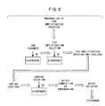
- a method for producing a DNA chip by supplying a large number of sample solutions onto a base plate comprising the steps of PCR-amplifying a DNA fragment to prepare a PCR product; drying the PCR product to prepare DNA powder; supplying the DNA powder into a solution supply apparatus; and supplying a buffer solution into the supply apparatus to prepare a sample solution; wherein the sample solution in the supply apparatus is supplied onto the base plate by using the supply apparatus to produce the DNA chip.
- the process for mixing the DNA powder and the buffer solution to prepare the sample solution, and the step of supplying the sample solution onto the base plate are performed in the identical supply apparatus.
- the sample solution in the preparation vessel is moved in a powder state into the supply apparatus. Accordingly, it is possible to reduce any sample residue adhered, for example, to the vessel wall in the preparation vessel. Further, for example, it is unnecessary to use any pipette to move or transfer the sample. Thus, it is possible to avoid the occurrence of any residue of the sample remained and discarded in the pipette.
- a method for producing a DNA chip comprising the steps of PCR-amplifying a DNA fragment to prepare a PCR product; supplying the prepared PCR product into a solution supply apparatus; drying the PCR product in the supply apparatus to prepare DNA powder; and supplying a buffer solution into the supply apparatus to prepare a sample solution; wherein the sample solution in the supply apparatus is supplied onto the base plate by using the supply apparatus to produce the DNA chip.
- the process for drying the PCR product to prepare the DNA powder, and the process for mixing the DNA powder and the buffer solution to prepare the sample solution are performed in the identical supply apparatus.
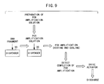
- a method for producing a DNA chip comprising the steps of PCR-amplifying a DNA fragment to prepare a PCR product in a solution supply apparatus; drying the PCR product in the supply apparatus to prepare DNA powder; and supplying a buffer solution into the supply apparatus to prepare a sample solution; wherein the sample solution in the supply apparatus is supplied onto the base plate by using the supply apparatus to produce the DNA chip.
- the series of steps ranging from the PCR amplification to the supply process are performed in the identical supply apparatus. Accordingly, the steps from the preparation of the sample solution to the supply process can be performed in accordance with the series of steps without deteriorating the quality of the sample solution. Further, it is possible to realize the simplification of the preservation equipment for the sample solution. It is possible to reduce the cost and improve the quality of the DNA chip.
- a method for producing a DNA chip comprising the step of PCR-amplifying a DNA fragment to prepare a PCR product in a solution supply apparatus; wherein the sample solution after preparation in the supply apparatus is supplied onto the base plate by using the supply apparatus to produce the DNA chip.
- the PCR product which is obtained by the PCR amplification in the supply apparatus, is directly supplied onto the base plate.
- the step of preparing the sample solution in the vessel is simplified. It is possible to efficiently produce the DNA chip in a short period of time. If any component, which inhibits the hybridization action after the produce of the DNA chip, included in any reagent used during the amplification, exists in the solution containing the PCR product in the supply apparatus, it is also preferable to pour a reagent to neutralize the action thereof.
- the sample solution is supplied in accordance with an ink-jet system.
- the supply apparatus is a dispenser comprising a plurality of arranged micropipettes each including a pouring port for pouring the sample solution from the outside, a cavity for pouring and charging the sample solution thereinto, and a discharge port for discharging the sample solution, formed on at least one or more substrates, the micropipette further including a piezoelectric/electrostrictive element disposed on at least one wall surface of the substrate which forms the cavity so that the sample solution is movable in the cavity, and mutually different types of the sample solutions being discharged from the discharge ports of the respective micropipettes.
- the sample solution is prepared by performing the steps of pouring, for example, the DNA powder obtained by drying each of the different kinds of PCR products, each of the different kinds of PCR products, original DNA before the PCR amplification and the buffer solution to dissolve the DNA powder therein, or PCR amplification reagents (for example, primers, enzyme, PCR buffer solution, dNTP's, distilled water) from the pouring ports into the plurality of cavities, and optionally drying the PCR product at the pouring port portion to prepare the DNA powder.
- the piezoelectric/electrostrictive element is driven, and thus the different types of the sample solutions in the plurality of cavities can be discharged from the discharge ports to produce the DNA chip.
- the piezoelectric/electrostrictive element which is formed on at least one wall surface of the substrate for forming the cavity, functions as a sensor for sensing the physical characteristic of the liquid in the cavity. Accordingly, it is possible to accurately detect the completion of preparation.
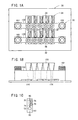
- a dispenser 30 as shown in FIGS. 1A to 1C and 2 is used for the method for producing the DNA chip according to the embodiment of the present invention.
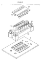
- the dispenser 30 includes, for example, ten micropipettes 34 which are arranged in five rows and two columns on the upper surface of a fixation plate 32 having a rectangular configuration. A group of the micropipettes 34, which are aligned in the direction of the respective columns, are fixed on the fixation plate 32 by the aid of a fixing jig 36 respectively.
- the micropipette 34 comprises a sample-pouring port 52 which is formed at the upper surface of a substrate 50 having a substantially rectangular parallelepiped-shaped configuration, a sample discharge port 54 which is formed at the lower surface of the substrate 50, a cavity 56 which is formed at the inside between the sample-pouring port 52 and the sample discharge port 54, and an actuator section 58 which is used to vibrate the substrate 50 or change the volume of the cavity 56.
- through-holes 40 are provided through the fixation plate 32 at portions corresponding to the sample discharge ports 54 of the micropipettes 34 respectively. Accordingly, a sample solution, which is discharged from the sample discharge port 54 of the micropipette 34, is supplied through the through-hole 40, for example, to a base plate 10 which is fixed under the fixation plate 32.
- An introducing bore 60 having a substantially L-shaped configuration with a wide opening width is formed over a region ranging from the sample-pouring port 52 to the inside of the substrate 50 in the micropipette 34.
- a first communication hole 62 having a small diameter is formed between the introducing bore 60 and the cavity 56. The sample solution, which is poured from the sample-pouring port 52, is introduced into the cavity 56 through the introducing bore 60 and the first communication hole 62.
- a second communication hole 64 which communicates with the sample discharge port 54 and which has a diameter larger than that of the first communication hole 62, is formed at a position different from that of the first communication hole 62, of the cavity 56.
- the first communication hole 62 is formed at the lower surface of the cavity 56.
- the position of the first communication hole 62 is deviated toward the sample-pouring port 52.
- the second communication hole 64 is formed at the position of the lower surface of the cavity 56 as well corresponding to the sample discharge port 54.
- the portion of the substrate 50, with which the upper surface of the cavity 56 makes contact is thin-walled to give a structure which tends to undergo the vibration with respect to the external stress so that the portion functions as a vibrating section 66.
- the actuator section 58 is formed on the upper surface of the vibrating section 66.
- the substrate 50 is constructed by laminating a plurality of green sheets made of zirconia ceramics (first thin plate layer 50A, first spacer layer 50B, second thin plate layer 50C, second spacer layer 50D, third spacer layer 50E, and third thin plate layer 50F), followed by sintering into one unit.
- the substrate 50 is constructed by laminating the thin-walled first thin plate layer 50A which is formed with a window for constructing the sample-pouring port 52 and which constitutes a part of the vibrating section 66, the thick-walled first spacer layer 50B which is formed with a part of the introducing bore 60 and a plurality of windows for constructing the cavity 56 respectively, the thin-walled second thin plate layer 50C which is formed with a part of the introducing bore 60 and a plurality of windows for constructing a part of the second communication hole 64 and the first communication hole 62 respectively, the thick-walled second spacer layer 50D which is formed with a plurality of windows for constructing a part of the introducing bore 60 and a part of the second communication hole 64 respectively, the thick-walled third spacer layer 50E which is formed with a window for constructing a part of the second communication hole 64, and the thin-walled third thin plate layer 50F which is formed with a window for constructing the sample discharge port 54, followed by sinter
- the actuator section 58 is constructed to have the vibrating section 66 described above as well as a lower electrode 70 which is directly formed on the vibrating section 66, a piezoelectric layer 72 which is composed of, for example, a piezoelectric/electrostrictive layer or an anti-ferroelectric layer formed on the lower electrode 70, and an upper electrode 74 which is formed on the upper surface of the piezoelectric layer 72.
- the lower electrode 70 and the upper electrode 74 are electrically connected to an unillustrated driving circuit via a plurality of pads 76, 78 which are formed on the upper surface of the substrate 50 respectively.
- the micropipette 34 constructed as described above is operated as follows. That is, when an electric field is generated between the upper electrode 74 and the lower electrode 70, then the piezoelectric layer 72 is deformed, and the vibrating section 66 is deformed in accordance therewith. Accordingly, the volume of the cavity (pressurizing chamber) 56 contacting with the vibrating section 66 is decreased or increased.
- the sample solution charged in the cavity 56 is discharged at a predetermined speed from the sample discharge port 54 which communicates with the cavity 56.
- the sample discharge port 54 which communicates with the cavity 56.
- FIG. 5 it is possible to produce a DNA chip 20 in which the sample solutions discharged from the micropipettes 34 are aligned and fixed as minute spots 80 on a base plate 10 such as a microscopic slide glass.
- the volume of the cavity 56 is increased, the sample solution is newly poured and charged from the first communication hole 62 into the cavity 56 to make provision for the next discharge.
- An apparatus structure based on the so-called ink-jet system may be adopted as the structure in which the volume of the cavity 56 is decreased in accordance with the driving of the actuator section 58 (see Japanese Laid-Open Patent Publication No. 6-40030).
- the cavity (pressurizing chamber) 56 is formed to have such a flow passage dimension that the sample solution containing DNA fragments or the like is moved without any turbulence.
- the cavity 56 can be used as a part of the flow passage ranging from the sample-pouring port 52 to the sample discharge port 54.
- the sample can be introduced to the sample discharge port 54 without disturbing the flow of the sample solution which is moved from the sample-pouring port 52 via the introducing bore 60 and the first communication hole 62 to the inside of the cavity 56.
- the substrate 50 is the sintered product obtained by laminating the zirconia ceramics into one unit as described above.
- the substrate 50 may be a bonded product composed of a sintered matter of zirconia ceramics formed with the actuator section 58, and a metal or resin film or the like.
- the thin plate layer 50F, in which the sample discharge port 54 is formed is preferably a sheet obtained by processing an organic resin such as a PET film by means of an excimer laser or the like, or a sheet obtained by punching a metal such as a stainless steel film with a punch and die or the like, considering the matching with the processing method therefor.
- the sizes of the sample discharge port 54 and the first communication hole 62 are optimally designed depending on, for example, the physical property, the discharge amount, and the discharge speed of the sample solution to be discharged. However, they are preferably about 10 to 100 ⁇ m ⁇ .
- Each of the fixing jigs 36 has a holder plate 100 for pressing the plurality of micropipettes 34 against the fixation plate 32. Insertion holes for inserting screws 102 thereinto are formed through both end portions of the holder plate 100. When the screws 102 are inserted into the insertion holes, and they are screwed into the fixation plate 32, then the plurality of micropipettes 34 can be pressed against the fixation plate 32 by the aid of the holder plate 100 at once.
- One unit is constructed by the plurality of micropipettes 34 which are pressed by one holder plate 100.
- the example shown in FIG. 1A is illustrative of the case in which one unit is constructed by the five micropipettes 34 which are arranged in the direction of the column.
- the holder plate 100 is formed with introducing holes 104 (see FIG. 1B) which are used to supply the sample solutions to the portions corresponding to the sample-pouring ports 52 of the respective micropipettes 34 respectively when the plurality of micropipettes 34 are pressed. Tubes 106 for introducing the sample solution to the introducing holes 104 respectively are held at upper end portions of the respective introducing holes 104.
- the width of the holder plate 100 resides in such a dimension that the pads 76, 78 connected to the respective electrodes 70, 74 of the actuator section 58 are faced upwardly when the plurality of micropipettes 34 are pressed against the fixation plate 32.
- the dispenser 30 is constructed such that the plurality of micropipettes 34 each having the sample-pouring port 52 and the sample discharge port 54 are provided in an upstanding manner with the respective sample discharge ports 54 directed downwardly.
- the respective micropipettes 34 are aligned and arranged such that the respective sample-pouring ports 52 are disposed on the upper side, the sample discharge ports 54 are disposed on the lower side, and the respective sample discharge ports 54 are aligned two-dimensionally. Sample solutions of mutually different types are discharged from the sample discharge ports 54 respectively.
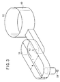
- a method is available, which is based on the used of a cartridge 112 arranged with a large number of recesses (storage sections) 110 each having a substantially V-shaped cross section.
- the following procedure is available. That is, the mutually different sample solutions are poured into the respective recesses 110 of the cartridge 112.
- the cartridge 112 is attached so that the respective recesses 110 correspond to the tubes 106 respectively.
- the bottoms of the respective recesses 110 are opened with needles or the like. Accordingly, the sample solutions in the respective recesses 110 are supplied via the tubes 106 to the respective micropipettes 34.
- the substrate 50 for constructing the micropipette 34 is formed of ceramics, for which it is possible to use, for example, fully stabilized zirconia, partially stabilized zirconia, alumina, magnesia, and silicon nitride.
- the fully stabilized/partially stabilized zirconia is used most preferably, because the mechanical strength is large even in the case of the thin plate, the toughness is high, and the reactivity with the piezoelectric layer 72 and the electrode material is small.
- piezoelectric ceramic for the piezoelectric layer 72 for constructing the actuator section 58 include, for example, lead zirconate, lead titanate, lead magnesium niobate, lead magnesium tantalate, lead nickel niobate, lead zinc niobate, lead manganese niobate, lead antimony stannate, lead manganese tungstate, lead cobalt niobate, and barium titanate, as well as composite ceramics containing components obtained by combining any of them.
- a material containing a major component composed of lead zirconate, lead titanate, and lead magnesium niobate is preferably used, because of the following reason.
- the upper electrode 74 and the lower electrode 70 of the actuator section 58 are made of metal which is solid at room temperature and which is conductive.
- metal simple substance of, for example, aluminum, titanium, chromium, iron, cobalt, nickel, copper, zinc, niobium, molybdenum, ruthenium, palladium, rhodium, silver, stannum, tantalum, tungsten, iridium, platinum, gold, and lead, or alloy obtained by combining any of them.
- a cermet material obtained by dispersing, in the metal described above, the same material as that of the piezoelectric layer 72 or the substrate 50.
- the completion of the PCR amplification in the cavity 56 and the completion of the preparation of the sample solution are recognized by sensing the change of the fluid characteristic in the cavity 56.
- the actuator section 58 is driven under a driving condition corresponding to the amount of liquid droplets suitable for the required spot diameter, and the sample solution is repeatedly supplied. Accordingly, the DNA chip 20 is produced. Usually, when one minute spot 80 is formed, one to several hundreds of droplet or droplets are discharged from the micropipette 34.
- substitution solution and the sample solution such that the existing gas in the solution is previously removed by performing the degassing operation.
- any bubble obstructs the flow passage at an intermediate portion to cause the defective charge upon the charge of the solution into the flow passage of the micropipette 34, then the inconvenience can be avoided by dissolving the bubble in the solution. Further, no bubble is generated in the fluid during the discharge, and no defective discharge is caused.
- the process for mixing the DNA powder and the buffer solution to prepare the sample solution the process for drying the PCR product to prepare the DNA powder followed by being mixed with the buffer solution to prepare the sample solution, or the process ranging from the PCR amplification to the preparation of the sample solution is performed in the identical dispenser 30.
Landscapes
- Chemical & Material Sciences (AREA)
- Health & Medical Sciences (AREA)
- Life Sciences & Earth Sciences (AREA)
- Organic Chemistry (AREA)
- General Health & Medical Sciences (AREA)
- Chemical Kinetics & Catalysis (AREA)
- Biochemistry (AREA)
- Clinical Laboratory Science (AREA)
- Analytical Chemistry (AREA)
- Immunology (AREA)
- Molecular Biology (AREA)
- Physics & Mathematics (AREA)
- Zoology (AREA)
- Proteomics, Peptides & Aminoacids (AREA)
- Engineering & Computer Science (AREA)
- Wood Science & Technology (AREA)
- Hematology (AREA)
- Microbiology (AREA)
- Biotechnology (AREA)
- Biophysics (AREA)
- Bioinformatics & Cheminformatics (AREA)
- General Engineering & Computer Science (AREA)
- Genetics & Genomics (AREA)
- General Physics & Mathematics (AREA)
- Pathology (AREA)
- Apparatus Associated With Microorganisms And Enzymes (AREA)
- Measuring Or Testing Involving Enzymes Or Micro-Organisms (AREA)
- Automatic Analysis And Handling Materials Therefor (AREA)
- Immobilizing And Processing Of Enzymes And Microorganisms (AREA)
Applications Claiming Priority (4)
| Application Number | Priority Date | Filing Date | Title |
|---|---|---|---|
| JP30162799 | 1999-10-22 | ||
| JP30162799 | 1999-10-22 | ||
| JP2000089979A JP2001186881A (ja) | 1999-10-22 | 2000-03-28 | Dnaチップの製造方法 |
| JP2000089979 | 2000-03-28 |
Publications (2)
| Publication Number | Publication Date |
|---|---|
| EP1094120A2 true EP1094120A2 (fr) | 2001-04-25 |
| EP1094120A3 EP1094120A3 (fr) | 2003-06-18 |
Family
ID=26562788
Family Applications (1)
| Application Number | Title | Priority Date | Filing Date |
|---|---|---|---|
| EP00309285A Withdrawn EP1094120A3 (fr) | 1999-10-22 | 2000-10-20 | Préparation d'une puce à ADN |
Country Status (3)
| Country | Link |
|---|---|
| US (1) | US6365378B1 (fr) |
| EP (1) | EP1094120A3 (fr) |
| JP (1) | JP2001186881A (fr) |
Cited By (4)
| Publication number | Priority date | Publication date | Assignee | Title |
|---|---|---|---|---|
| EP1385000A4 (fr) * | 2001-05-01 | 2006-04-19 | Ngk Insulators Ltd | Procede de fabrication de biopuces |
| US7220574B2 (en) | 2000-05-11 | 2007-05-22 | Fraunhafer-Gasellschaft Zur Forderung Der Angewandten Forschung E.V. | Hyphen-specific factors from Candida albicans |
| WO2010069977A1 (fr) * | 2008-12-17 | 2010-06-24 | Tecan Trading Ag | Système et instrument de traitement d'échantillons biologiques et de manipulation de liquides contenant des échantillons biologiques |
| US8357551B2 (en) | 2002-06-19 | 2013-01-22 | Semiconductor Energy Labortory Co., Ltd. | Method of manufacturing light emitting device |
Families Citing this family (31)
| Publication number | Priority date | Publication date | Assignee | Title |
|---|---|---|---|---|
| JP3492570B2 (ja) * | 1999-10-22 | 2004-02-03 | 日本碍子株式会社 | マイクロピペット及び分注装置 |
| JP3532829B2 (ja) * | 2000-05-17 | 2004-05-31 | 日立ソフトウエアエンジニアリング株式会社 | バイオチップ作成溶液及びバイオチップ作成方法 |
| US6740530B1 (en) | 2000-11-22 | 2004-05-25 | Xerox Corporation | Testing method and configurations for multi-ejector system |
| US6861034B1 (en) | 2000-11-22 | 2005-03-01 | Xerox Corporation | Priming mechanisms for drop ejection devices |
| US6623700B1 (en) * | 2000-11-22 | 2003-09-23 | Xerox Corporation | Level sense and control system for biofluid drop ejection devices |
| US6713022B1 (en) * | 2000-11-22 | 2004-03-30 | Xerox Corporation | Devices for biofluid drop ejection |
| US20050226786A1 (en) * | 2001-03-08 | 2005-10-13 | Hager David C | Multi-well apparatus |
| NZ528650A (en) | 2001-03-08 | 2005-09-30 | Exelixis Inc | Multi-well apparatus |
| AU2002362446A1 (en) * | 2001-10-03 | 2003-04-14 | Kin Chiu Ng | Apparatus and method for fabricating high density microarrays and applications thereof |
| JP3892743B2 (ja) * | 2002-03-01 | 2007-03-14 | 日本碍子株式会社 | 反応セルおよびその使用方法 |
| JP2004045346A (ja) * | 2002-07-16 | 2004-02-12 | Nisshinbo Ind Inc | マイクロアレイの作製方法 |
| EP1617217A4 (fr) * | 2003-03-14 | 2009-10-28 | Kitakyushu Foundation | Puce d'immobilisation d'une substance organique et son utilisation |
| US6843281B1 (en) | 2003-07-30 | 2005-01-18 | Agilent Techinologies, Inc. | Methods and apparatus for introducing liquids into microfluidic chambers |
| US7601532B2 (en) | 2003-09-25 | 2009-10-13 | Hisamitsu Pharmaceutical Co., Inc. | Microarray for predicting the prognosis of neuroblastoma and method for predicting the prognosis of neuroblastoma |
| US7119942B2 (en) * | 2004-06-30 | 2006-10-10 | Northrop Gruman Corporation | Side spring micro-mirror |
| KR100707171B1 (ko) * | 2004-08-31 | 2007-04-13 | 삼성전자주식회사 | Pcr을 수행할 수 있는 잉크젯 방식의 dna 어레이어및 이를 이용한 dna 마이크로어레이의 제조방법 |
| JP4103009B2 (ja) * | 2005-03-23 | 2008-06-18 | セイコーエプソン株式会社 | 液滴吐出装置、およびマイクロアレイ製造方法 |
| US8263414B2 (en) * | 2005-05-23 | 2012-09-11 | Siemens Healthcare Diagnostics Inc. | Dispensing of a diagnostic liquid onto a diagnostic reagent |
| JP4497370B2 (ja) | 2005-05-31 | 2010-07-07 | 日本碍子株式会社 | 微小物体の飛翔状態検出装置、及び微小物体の飛翔状態検出方法 |
| JP4863993B2 (ja) | 2005-05-31 | 2012-01-25 | 日本碍子株式会社 | 物体の通過検出装置 |
| JP4906416B2 (ja) | 2006-07-11 | 2012-03-28 | 日本碍子株式会社 | 物体の通過検出装置 |
| WO2015138343A1 (fr) | 2014-03-10 | 2015-09-17 | Click Diagnostics, Inc. | Thermocycleur à base de cartouches |
| ES2898103T3 (es) | 2014-12-31 | 2022-03-03 | Visby Medical Inc | Dispositivos para pruebas de diagnóstico molecular |
| US10987674B2 (en) | 2016-04-22 | 2021-04-27 | Visby Medical, Inc. | Printed circuit board heater for an amplification module |
| WO2017197040A1 (fr) | 2016-05-11 | 2017-11-16 | Click Diagnostics, Inc. | Compositions et méthodes d'extraction d'acides nucléiques |
| WO2018005710A1 (fr) | 2016-06-29 | 2018-01-04 | Click Diagnostics, Inc. | Dispositifs et procédés pour la détection de molécules au moyen d'une cuve à circulation |
| USD800331S1 (en) | 2016-06-29 | 2017-10-17 | Click Diagnostics, Inc. | Molecular diagnostic device |
| USD800914S1 (en) | 2016-06-30 | 2017-10-24 | Click Diagnostics, Inc. | Status indicator for molecular diagnostic device |
| USD800913S1 (en) | 2016-06-30 | 2017-10-24 | Click Diagnostics, Inc. | Detection window for molecular diagnostic device |
| KR20200079264A (ko) | 2017-11-09 | 2020-07-02 | 비스비 메디컬, 인코포레이티드 | 표적 바이러스 검출을 위한 휴대용 분자 진단 디바이스 및 방법 |
| USD1064314S1 (en) | 2021-08-13 | 2025-02-25 | Visby Medical, Inc. | Molecular diagnostic device |
Family Cites Families (7)
| Publication number | Priority date | Publication date | Assignee | Title |
|---|---|---|---|---|
| US5849486A (en) * | 1993-11-01 | 1998-12-15 | Nanogen, Inc. | Methods for hybridization analysis utilizing electrically controlled hybridization |
| JP3144948B2 (ja) | 1992-05-27 | 2001-03-12 | 日本碍子株式会社 | インクジェットプリントヘッド |
| US5807522A (en) * | 1994-06-17 | 1998-09-15 | The Board Of Trustees Of The Leland Stanford Junior University | Methods for fabricating microarrays of biological samples |
| JP3388060B2 (ja) | 1994-11-25 | 2003-03-17 | 日本碍子株式会社 | 流体の特性測定用素子及び流体の特性測定装置 |
| US6024925A (en) * | 1997-01-23 | 2000-02-15 | Sequenom, Inc. | Systems and methods for preparing low volume analyte array elements |
| CA2320462A1 (fr) * | 1998-02-09 | 1999-08-12 | Toyo Kohan Co., Ltd. | Substrats d'immobilisation et d'amplification de l'adn, cristaux de blocage d'adn avec de l'adn bloque sur les substrats, et procede d'amplification de l'adn |
| DE19819537A1 (de) * | 1998-04-30 | 2000-03-16 | Biochip Technologies Gmbh | Analyse- und Diagnostikinstrument |
-
2000
- 2000-03-28 JP JP2000089979A patent/JP2001186881A/ja active Pending
- 2000-10-20 EP EP00309285A patent/EP1094120A3/fr not_active Withdrawn
- 2000-10-23 US US09/694,157 patent/US6365378B1/en not_active Expired - Fee Related
Cited By (13)
| Publication number | Priority date | Publication date | Assignee | Title |
|---|---|---|---|---|
| US7220574B2 (en) | 2000-05-11 | 2007-05-22 | Fraunhafer-Gasellschaft Zur Forderung Der Angewandten Forschung E.V. | Hyphen-specific factors from Candida albicans |
| US7160512B2 (en) | 2001-05-01 | 2007-01-09 | Ngk Insulators, Ltd. | Method for manufacturing biochips |
| EP1385000A4 (fr) * | 2001-05-01 | 2006-04-19 | Ngk Insulators Ltd | Procede de fabrication de biopuces |
| US8357551B2 (en) | 2002-06-19 | 2013-01-22 | Semiconductor Energy Labortory Co., Ltd. | Method of manufacturing light emitting device |
| US8906714B2 (en) | 2002-06-19 | 2014-12-09 | Semiconductor Energy Laboratory Co., Ltd. | Method of manufacturing light emitting device |
| EP2602333A1 (fr) * | 2008-12-17 | 2013-06-12 | Tecan Trading AG | Systeme et instrument de traitement d'echantillons biologiques et de manipulation de liquides contenant des echantillons biologiques |
| CH700127A1 (de) * | 2008-12-17 | 2010-06-30 | Tecan Trading Ag | System und Vorrichtung zur Aufarbeitung biologischer Proben und zur Manipulation von Flüssigkeiten mit biologischen Proben. |
| US8882982B2 (en) | 2008-12-17 | 2014-11-11 | Tecan Trading Ag | System and instrument for processing biological samples and manipulating liquids having biological samples |
| WO2010069977A1 (fr) * | 2008-12-17 | 2010-06-24 | Tecan Trading Ag | Système et instrument de traitement d'échantillons biologiques et de manipulation de liquides contenant des échantillons biologiques |
| US8936708B2 (en) | 2008-12-17 | 2015-01-20 | Tecan Trading Ag | Manipulating the size of liquid droplets in digital microfluidics |
| US9545631B2 (en) | 2008-12-17 | 2017-01-17 | Tecan Trading Ag | Cartridge, kit and method for processing biological samples and manipulating liquids having biological samples |
| US10357773B2 (en) | 2008-12-17 | 2019-07-23 | Tecan Trading Ag | Cartridge, kit and method for manipulating liquids having biological samples |
| US10632467B2 (en) | 2008-12-17 | 2020-04-28 | Tecan Trading Ag | Cartridge, kit and method for manipulating liquids having biological samples |
Also Published As
| Publication number | Publication date |
|---|---|
| JP2001186881A (ja) | 2001-07-10 |
| US6365378B1 (en) | 2002-04-02 |
| EP1094120A3 (fr) | 2003-06-18 |
Similar Documents
| Publication | Publication Date | Title |
|---|---|---|
| US6365378B1 (en) | Method for producing DNA chip | |
| EP1143252B1 (fr) | Biopuce | |
| EP1094119B1 (fr) | Préparation d'une puce à ADN | |
| EP1101532B1 (fr) | Distributeur de liquide pour la production des micro-ensembles d'ADN | |
| EP1094318B1 (fr) | Chip d'ADN et sa préparation | |
| EP1365249B1 (fr) | Procede de fabrication d'une puce biologique | |
| US7160511B2 (en) | Liquid pipetting apparatus and micro array manufacturing apparatus | |
| JPWO2001029561A1 (ja) | バイオチップ | |
| JP2001337096A (ja) | 分注装置及びdnaチップの製造方法 | |
| JP3647369B2 (ja) | Dnaチップ及びその製造方法 | |
| JP3492570B2 (ja) | マイクロピペット及び分注装置 | |
| JP4095005B2 (ja) | Dnaチップの製造方法 | |
| JP3991049B2 (ja) | 分注装置及びdnaチップの製造方法 | |
| JP2006078498A (ja) | Dnaチップの製造方法 | |
| JP2005099050A (ja) | 分注装置及びdnaチップの製造方法 |
Legal Events
| Date | Code | Title | Description |
|---|---|---|---|
| PUAI | Public reference made under article 153(3) epc to a published international application that has entered the european phase |
Free format text: ORIGINAL CODE: 0009012 |
|
| AK | Designated contracting states |
Kind code of ref document: A2 Designated state(s): AT BE CH CY DE DK ES FI FR GB GR IE IT LI LU MC NL PT SE |
|
| AX | Request for extension of the european patent |
Free format text: AL;LT;LV;MK;RO;SI |
|
| PUAL | Search report despatched |
Free format text: ORIGINAL CODE: 0009013 |
|
| STAA | Information on the status of an ep patent application or granted ep patent |
Free format text: STATUS: THE APPLICATION HAS BEEN WITHDRAWN |
|
| RIC1 | Information provided on ipc code assigned before grant |
Ipc: 7G 01N 33/573 B Ipc: 7B 01L 3/02 B Ipc: 7B 01J 19/00 B Ipc: 7B 01L 3/00 B Ipc: 7C 12Q 1/68 A |
|
| AK | Designated contracting states |
Designated state(s): AT BE CH CY DE DK ES FI FR GB GR IE IT LI LU MC NL PT SE |
|
| AX | Request for extension of the european patent |
Extension state: AL LT LV MK RO SI |
|
| 18W | Application withdrawn |
Effective date: 20030429 |