EP1094238A2 - Dispositif de support élastique et structure de montage d'un équipement avec ce dispositif - Google Patents
Dispositif de support élastique et structure de montage d'un équipement avec ce dispositif Download PDFInfo
- Publication number
- EP1094238A2 EP1094238A2 EP20000300899 EP00300899A EP1094238A2 EP 1094238 A2 EP1094238 A2 EP 1094238A2 EP 20000300899 EP20000300899 EP 20000300899 EP 00300899 A EP00300899 A EP 00300899A EP 1094238 A2 EP1094238 A2 EP 1094238A2
- Authority
- EP
- European Patent Office
- Prior art keywords
- resilient
- mounting apparatus
- collar
- sleeve
- resilient mounting
- Prior art date
- Legal status (The legal status is an assumption and is not a legal conclusion. Google has not performed a legal analysis and makes no representation as to the accuracy of the status listed.)
- Withdrawn
Links
Images


Classifications
-
- F—MECHANICAL ENGINEERING; LIGHTING; HEATING; WEAPONS; BLASTING
- F16—ENGINEERING ELEMENTS AND UNITS; GENERAL MEASURES FOR PRODUCING AND MAINTAINING EFFECTIVE FUNCTIONING OF MACHINES OR INSTALLATIONS; THERMAL INSULATION IN GENERAL
- F16F—SPRINGS; SHOCK-ABSORBERS; MEANS FOR DAMPING VIBRATION
- F16F15/00—Suppression of vibrations in systems; Means or arrangements for avoiding or reducing out-of-balance forces, e.g. due to motion
- F16F15/02—Suppression of vibrations of non-rotating, e.g. reciprocating systems; Suppression of vibrations of rotating systems by use of members not moving with the rotating systems
- F16F15/04—Suppression of vibrations of non-rotating, e.g. reciprocating systems; Suppression of vibrations of rotating systems by use of members not moving with the rotating systems using elastic means
- F16F15/08—Suppression of vibrations of non-rotating, e.g. reciprocating systems; Suppression of vibrations of rotating systems by use of members not moving with the rotating systems using elastic means with rubber springs ; with springs made of rubber and metal
-
- F—MECHANICAL ENGINEERING; LIGHTING; HEATING; WEAPONS; BLASTING
- F16—ENGINEERING ELEMENTS AND UNITS; GENERAL MEASURES FOR PRODUCING AND MAINTAINING EFFECTIVE FUNCTIONING OF MACHINES OR INSTALLATIONS; THERMAL INSULATION IN GENERAL
- F16F—SPRINGS; SHOCK-ABSORBERS; MEANS FOR DAMPING VIBRATION
- F16F1/00—Springs
- F16F1/36—Springs made of rubber or other material having high internal friction, e.g. thermoplastic elastomers
- F16F1/373—Springs made of rubber or other material having high internal friction, e.g. thermoplastic elastomers characterised by having a particular shape
- F16F1/3732—Springs made of rubber or other material having high internal friction, e.g. thermoplastic elastomers characterised by having a particular shape having an annular or the like shape, e.g. grommet-type resilient mountings
Definitions
- the present invention relates to a resilient mounting apparatus to be mounted to equipment generating shocks, vibrations, or structure-borne noise, or to be mounted to equipment which is prone to respond shocks, vibrations, or structure-borne noise transmitted from a foundation.
- a resilient mounting apparatus of this type needs to be compact in size so that it can be disposed in a small space, needs to prevent vibrations and noise while appropriately suppressing deformation, and needs to be excellent in fatigue strength.
- a resilient mounting apparatus m comprises a flanged 01 collar 02, a cylindrical portion 03 integrally connected to the collar 02, and a resilient rubber body 05.
- an annular rebound member 06 formed separately from the resilient mounting apparatus m shown in Fig. 4B and a sleeve 07 shown in Fig. 4C accompany the resilient mounting apparatus m.
- the resilient mounting apparatus in shown in Fig. 4A is loosely fitted around the sleeve 07 with a clearance 08 therebetween, the annular rebound member 06 shown in Fig. 4B surrounding the sleeve 07 is set on the upper portion of the resilient mounting apparatus m, and a washer 09 is set on an upper surface of the rebound member 06.
- a bolt 010 is inserted through these set elements and threaded into a foundation 011 so that the set elements are fixed.
- the equipment mounting structure is assembled such that an equipment bracket 012 is placed on an upper surface of the flange 01 of the collar 02 and the rebound member 06 is displaced between the equipment bracket 012 and the washer 09.
- the equipment mounting structure using the above-described resilient amounting apparatus has the following inconvenience.
- Another object of the invention is to provide a resilient mounting apparatus which is easy to retrofit into an existing construction.
- Another object of the invention is to provide a resilient mounting apparatus suitable for supporting the equipment in an underslung manner.
- Another object of the invention is to provide a resilient mounting apparatus with long service life.
- a resilient mounting apparatus of the present invention comprises a collar, a resilient body and a sleeve which are all integrally formed into one unit, the collar comprises a tubular portion and a flange portion continuously connected to the tubular portion; the resilient body comprises a neck portion concentrically provided in an inner surface of the collar and a pad portion extending to the flange portion, the resilient body being provided at its central portion with an insertion hole for a fixing tool; the sleeve is integrally provided on an inner surface of the resilient body such as to protrude from an upper end of the collar; and a lower end of the pad portion of the resilient body protrudes from a lower end of the sleeve.
- the underslung manner is most preferable for the equipment mounting structure. That is, using any one of the above-described resilient mounting apparatuses, an upper portion of a neck portion is abutted against a lower surface of a foundation and the neck portion is held by a fixing tool in an underslung state, and an equipment mounting bracket is held on an upper surface of a flange of a collar of the resilient mounting apparatus in an underslung state.
- Figs. 1A and 1B are a perspective view and a sectional view of a resilient mounting apparatus, respectively.
- the resilient mounting apparatus M of the present application comprises three components, i.e., a collar 1, a resilient body 2 and a sleeve 3. It is preferable that these three components are integrally vulcanized to form one unit.
- the collar 1 comprises a cylindrical tubular portion 1a and a disk-like flange 1b smoothly and continuously connected to the tubular portion 1a. It is preferable that the collar 1 is made of non-corrosive metal which strong and has abrasion resistance.
- the collar 1 transmits axial load and radial load acting between the resilient body and an equipment bracket 9 (Fig. 2) mounted to the resilient body 2, and protects the resilient body such that the resilient body should not be cut or abraded by any sharp edge or the like.
- the resilient body 2 comprises a tubular neck portion 2a and a flat pat portion 2b smoothly and continuously connected to the neck portion 2a.
- the neck portion 2a has an upper portion 2c sandwiched between tubular portion 1a of the collar 1 and the sleeve 3, and the upper portion 2c axially extends beyond the tubular portion 1 such as to cover a leading end of the tubular portion 1a.
- a head portion of the upper portion 2c is formed in an arc and is projecting beyond an upper portion of the sleeve 3.
- a diameter of the pad portion 2b is smaller than that of the flange 1b, and a lower end of the pad portion 2b includes a protrusion 2d protruding from a lower end of the sleeve 3 by a distance ⁇ .
- An end surface of the lower end of the pad portion 2b serves as a base surface 2g which contacts with a washer 4 (Fig.
- the protrusion amount ⁇ of the protrusion 2d is set equal to a displacement amount generated when an axial static load is applied. That is, when no load is applied to the resilient mounting apparatus M, due to this protrusion 2d, the resilient body 2 and the collar 1 are displaced axially toward the end of the neck portion 2a while causing static shear in the neck portion 2a.
- the resilient body 2 is made of soft and elastic rubber having selected hardness and damping ratio, The resilient body 2 provides cushioning and damping of shock, vibration and the like from both the axial and radial directions of the resilient mounting apparatus.
- the dimensions of the neck portion 2a and the pad portion 2b can be decided individually, depending on the desired properties in different directions and on the available space. For example, for the pad portion 2b, its diameter and thickness are decided depending on the desired axial stiffness and the applied static load (equipment weight).
- the height of the neck portion 2a is decided mainly depending on the equipment bracket 9 and a required clearance b (Fig. 2) between equipment 10 and a foundation 8. The outer diameter of the neck portion 2a is normally minimized so as not to require large mounting holes in the equipment bracket 9.
- the sleeve 3 is disposed concentrically with the tubular portion 1a of the collar 1, and an upper end of the sleeve 3 protrudes from the tip end of the tubular portion 1a by a protrusion amount a. Therefore, when the resilient mounting apparatus M is installed, the upper portion 2c of the collar 1 is interposed between the equipment 10 and the foundation 8 so that a constant distance b can be maintained. Further, a base for fastening the mounting bolt 5 and a nut 6 (Fig. 2) can be secured, and generated radial force can be transmitted from the foundation to the resilient body 2. It is preferable that the sleeve 3 is made of high rigid and strong metal having abrasion resistance.
- the pad portion 2b when the axial static load (e.g., the suspended equipment weight) is applied, the pad portion 2b is compressed through the collar 1 and the tubular portion returns to near its original, stress free state. This is intended to minimize the static strain of the tubular neck portion 2a and thereby the risk of delamination between the resilient body 2 and the sleeve 3 is minimized.
- the inner chamfer 2c of the pad portion 2b is intended to limit the strain in the resilient body 2 near that end of the sleeve 3 while the outer chamfer intends to limit the maximum tensile strain due to hoop stress generated in the pad portion 2b, thereby aiming to minimize the risk of delamination and to maximize the life of the resilient body 2.
- Fig. 2 is an enlarged view of a state in which the resilient mounting apparatus is used.
- the resilient mounting apparatus is loaded with suspended equipment in an underslung application.
- the resilient mounting apparatus M is intended to be installed with the static load being applied in the axial direction and loading the pad portion 2b in compression.
- the resilient mounting apparatus is normally installed with its symmetric axis oriented vertically.
- the resilient mounting apparatus M may be oriented with its pad portion 2b pointing either upwards or downwards. This choice may be determined by, e.g., space constraints as-installed or by access constraints during installation or for inspection.
- the resilient mounting apparatus Compared to a normal, rigid equipment installation using the same bolt diameter and having the equipment brackets bolted directly to the foundation, the resilient mounting apparatus needs the following points:
- a clearance b in the axial (vertical) direction between the foundation 8 and the equipment bracket 9 is large enough to accommodate occurring vibrations without contact. About 1 mm is often sufficient.
- a diameter of the mounting hole M where the resilient mounting apparatus is to be installed, i.e., either on the foundation 8 or on the equipment bracket 9 is large enough for the neck portion 2a of the resilient mounting apparatus to be inserted. In this case, some free space is required on either the foundation 8 or the equipment bracket 9, large enough to accommodate the pad portion 2b of the resilient mounting apparatus together with a washer 4 and a nut 6.
- the equipment is jacked in place and then, the bolt 5, the resilient mounting apparatus M, the bottom washer 4 and the nut 6 are mounted in the mounting hole 8a of the foundation in this order.
- the nut 6 is tightened until the bottom washer 4 contacts the sleeve 3 so that the equipment is supported by the foundation 8 alone.
- the clearance b generated between the foundation 8 and the equipment bracket 9, and the clearance of any connecting cables, air ducts, piping etc. If the clearance b to the foundation is insufficient, small diameter spacing washers may be added to one end or both ends of the sleeve 3 to effectively extend the sleeve 3. If the clearances are satisfactory, nut 6 is tightened to the required torque and a split pin 7 or similar is mounted to each resilient mounting apparatus M.
- the mounting hole on either the foundation 8 or the equipment bracket 9 must first be enlarged. If this is done on the hole of the equipment bracket 9, it can normally be done with the equipment 10 left in place, just lowered a few mm and supported, but it is necessary to take care not to drill into the foundation 8. When a jig is inserted into the hole of the foundation 8 to widen the same, it is necessary to ensure that the enlarged hole is centered.
- Fig. 2 the load is supported by the bolt 5, the bottom washer 4 and the nut 6.
- the bolt 5 is subjected to tension and bending.
- the highest stresses occurs at the head fillet.
- the largest stress component is normally the static axial tensile stress caused by the tightening of the nut 6 to required torque, which is the same as for a normal rigid mounting.
- the dynamic tensile stresses caused by shocks and vibrations in the axial direction, which are less than for a rigid mounting by a normal bolt.
- the radial dynamic tensile stresses by shocks and vibrations are also generated.
- the bottom washer 4 is subjected to bending due to the axial static and dynamic forces. These stresses are controlled by making the washer sufficiently thick.
- the nut 6 is loaded as for a rigid mount by the bolt 5, but with lower axial dynamic forces.
- the above components should be dimensioned against yield and fatigue, including collision.
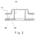
- Fig. 3 shows another embodiment of a resilient mounting apparatus.
- the basic structure is the same as that shown in Fig. 1. That is, a collar 101, a resilient body 102 and a sleeve 103 are integrally vulcanized to form one unit.
- a washer 104 is integrally vulcanized to a lower end surface of the resilient body 102 into one unit, or is adhered to the lower end surface using adhesive. With this arrangement, the washer should cot be lost at the time of installation or maintenance, and the washer is prevented from being replaced by another washer having improper strength.
- the resilient mounting apparatus is used for holding the equipment as a retrofit, since the bolt and the washer play important rolls for supporting the static [an] and dynamic loads, it is important that the resilient body 102 and the washer 104 are integrally formed.
- the resilient mounting apparatus can also be applied to a system in which the equipment is supported on the foundation.
- the resilient mounting apparatus is provided on the, and the bracket is placed on the collar.
Landscapes
- Engineering & Computer Science (AREA)
- General Engineering & Computer Science (AREA)
- Mechanical Engineering (AREA)
- Chemical & Material Sciences (AREA)
- Combustion & Propulsion (AREA)
- Physics & Mathematics (AREA)
- Acoustics & Sound (AREA)
- Aviation & Aerospace Engineering (AREA)
- Vibration Prevention Devices (AREA)
- Springs (AREA)
Applications Claiming Priority (2)
| Application Number | Priority Date | Filing Date | Title |
|---|---|---|---|
| JP30124599 | 1999-10-22 | ||
| JP30124599A JP3212580B2 (ja) | 1999-10-22 | 1999-10-22 | 弾性マウント及びこれを用いた機器取付構造 |
Publications (1)
| Publication Number | Publication Date |
|---|---|
| EP1094238A2 true EP1094238A2 (fr) | 2001-04-25 |
Family
ID=17894530
Family Applications (1)
| Application Number | Title | Priority Date | Filing Date |
|---|---|---|---|
| EP20000300899 Withdrawn EP1094238A2 (fr) | 1999-10-22 | 2000-02-04 | Dispositif de support élastique et structure de montage d'un équipement avec ce dispositif |
Country Status (2)
| Country | Link |
|---|---|
| EP (1) | EP1094238A2 (fr) |
| JP (1) | JP3212580B2 (fr) |
Cited By (1)
| Publication number | Priority date | Publication date | Assignee | Title |
|---|---|---|---|---|
| CN101922685B (zh) * | 2010-01-11 | 2012-12-19 | 海洋王照明科技股份有限公司 | 一种减振器及使用该减振器的灯具 |
Families Citing this family (3)
| Publication number | Priority date | Publication date | Assignee | Title |
|---|---|---|---|---|
| JP4623304B2 (ja) * | 2006-03-03 | 2011-02-02 | Nok株式会社 | 防振マウント |
| JP2012235851A (ja) * | 2011-05-11 | 2012-12-06 | Sharp Corp | ドラム式洗濯機 |
| KR101410779B1 (ko) | 2012-09-11 | 2014-06-23 | 두산중공업 주식회사 | 브로치 머신의 센터링을 위한 센터링게이지 지그 및 이를 이용한 브로치 머신 센터링 방법 |
Citations (4)
| Publication number | Priority date | Publication date | Assignee | Title |
|---|---|---|---|---|
| US4530491A (en) | 1983-11-23 | 1985-07-23 | Lord Corporation | Compact low-frequency engine mounting |
| US4858880A (en) | 1987-05-29 | 1989-08-22 | Caterpillar Inc. | Resilient load supporting and motion accommodating mounting apparatus |
| US4921203A (en) | 1989-01-30 | 1990-05-01 | Buell Industries, Inc. | Spring element for a shock isolating mount |
| US5127698A (en) | 1990-04-12 | 1992-07-07 | Mercedes-Benz Ag | Support bearing |
Family Cites Families (2)
| Publication number | Priority date | Publication date | Assignee | Title |
|---|---|---|---|---|
| JPS6037638U (ja) * | 1983-08-23 | 1985-03-15 | 三菱重工業株式会社 | 防振ゴム |
| JPH0128358Y2 (fr) * | 1986-01-31 | 1989-08-29 |
-
1999
- 1999-10-22 JP JP30124599A patent/JP3212580B2/ja not_active Expired - Fee Related
-
2000
- 2000-02-04 EP EP20000300899 patent/EP1094238A2/fr not_active Withdrawn
Patent Citations (4)
| Publication number | Priority date | Publication date | Assignee | Title |
|---|---|---|---|---|
| US4530491A (en) | 1983-11-23 | 1985-07-23 | Lord Corporation | Compact low-frequency engine mounting |
| US4858880A (en) | 1987-05-29 | 1989-08-22 | Caterpillar Inc. | Resilient load supporting and motion accommodating mounting apparatus |
| US4921203A (en) | 1989-01-30 | 1990-05-01 | Buell Industries, Inc. | Spring element for a shock isolating mount |
| US5127698A (en) | 1990-04-12 | 1992-07-07 | Mercedes-Benz Ag | Support bearing |
Cited By (1)
| Publication number | Priority date | Publication date | Assignee | Title |
|---|---|---|---|---|
| CN101922685B (zh) * | 2010-01-11 | 2012-12-19 | 海洋王照明科技股份有限公司 | 一种减振器及使用该减振器的灯具 |
Also Published As
| Publication number | Publication date |
|---|---|
| JP3212580B2 (ja) | 2001-09-25 |
| JP2001124145A (ja) | 2001-05-08 |
Similar Documents
| Publication | Publication Date | Title |
|---|---|---|
| EP0066815B1 (fr) | Support pour unité motrice | |
| KR880001908B1 (ko) | 철도차용 제 1 차 차대받이 장치 | |
| EP0336627A2 (fr) | Support élastique | |
| US7954793B2 (en) | Elastomeric isolator | |
| CA1048474A (fr) | Ensemble de vehicule automoteur a support souple | |
| US20020158385A1 (en) | Thrust spring | |
| US20050133325A1 (en) | Dynamic damper | |
| US4521004A (en) | Vibration-isolating mounting with load-directing chamfer | |
| US10215248B2 (en) | Support for a driver's cab of a vehicle | |
| US4012071A (en) | Cab mounting device | |
| JPH0155699B2 (fr) | ||
| US20170051805A1 (en) | Vibration isolation member | |
| US5667202A (en) | Hybrid elastomer-and-metal spring isolator | |
| US20230375038A1 (en) | Bearing assembly for bearing a device | |
| US20050218288A1 (en) | Mounting system allowing for thermal expansion of an engine of a generator set | |
| EP1094238A2 (fr) | Dispositif de support élastique et structure de montage d'un équipement avec ce dispositif | |
| US6786646B2 (en) | Mount for a piston-cylinder assembly | |
| US20030020218A1 (en) | Air spring with two part housing | |
| EP0058545A1 (fr) | Attache élastique | |
| EP0851143B1 (fr) | Fixation pour carrosserie | |
| CN218971744U (zh) | 一种压缩机连接件和汽车 | |
| CN218777520U (zh) | 一种轨道车辆转向架用一系弹簧组和轨道车辆转向架 | |
| US20010030274A1 (en) | Shock and vibration mount | |
| JP2020142676A (ja) | 軸はり装置用防振ブッシュ | |
| US20060001203A1 (en) | Connecting bearing |
Legal Events
| Date | Code | Title | Description |
|---|---|---|---|
| PUAI | Public reference made under article 153(3) epc to a published international application that has entered the european phase |
Free format text: ORIGINAL CODE: 0009012 |
|
| AK | Designated contracting states |
Kind code of ref document: A2 Designated state(s): AT BE CH CY DE DK ES FI FR GB GR IE IT LI LU MC NL PT SE |
|
| AX | Request for extension of the european patent |
Free format text: AL;LT;LV;MK;RO;SI |
|
| STAA | Information on the status of an ep patent application or granted ep patent |
Free format text: STATUS: THE APPLICATION IS DEEMED TO BE WITHDRAWN |
|
| 18D | Application deemed to be withdrawn |
Effective date: 20020903 |