EP1094267A1 - Dispositif pour atténuer le son structurel dans tuyauteries - Google Patents
Dispositif pour atténuer le son structurel dans tuyauteries Download PDFInfo
- Publication number
- EP1094267A1 EP1094267A1 EP99121112A EP99121112A EP1094267A1 EP 1094267 A1 EP1094267 A1 EP 1094267A1 EP 99121112 A EP99121112 A EP 99121112A EP 99121112 A EP99121112 A EP 99121112A EP 1094267 A1 EP1094267 A1 EP 1094267A1
- Authority
- EP
- European Patent Office
- Prior art keywords
- arrangement
- intermediate medium
- particular according
- line
- connection ends
- Prior art date
- Legal status (The legal status is an assumption and is not a legal conclusion. Google has not performed a legal analysis and makes no representation as to the accuracy of the status listed.)
- Withdrawn
Links
- 239000012530 fluid Substances 0.000 claims abstract description 7
- 230000010349 pulsation Effects 0.000 claims description 30
- 230000005540 biological transmission Effects 0.000 claims description 14
- 238000013016 damping Methods 0.000 claims description 7
- 238000003825 pressing Methods 0.000 claims description 7
- 239000000463 material Substances 0.000 claims description 6
- 238000000926 separation method Methods 0.000 claims description 5
- 239000013013 elastic material Substances 0.000 claims description 3
- 239000007779 soft material Substances 0.000 claims description 2
- 229920000642 polymer Polymers 0.000 claims 2
- 210000000056 organ Anatomy 0.000 claims 1
- 229920001971 elastomer Polymers 0.000 abstract description 5
- 239000000806 elastomer Substances 0.000 abstract description 4
- 238000009413 insulation Methods 0.000 description 16
- 230000006870 function Effects 0.000 description 13
- 239000007788 liquid Substances 0.000 description 11
- 239000003638 chemical reducing agent Substances 0.000 description 8
- 238000007789 sealing Methods 0.000 description 6
- 238000005516 engineering process Methods 0.000 description 3
- 239000004033 plastic Substances 0.000 description 3
- 229920003023 plastic Polymers 0.000 description 3
- 239000002861 polymer material Substances 0.000 description 3
- 238000010521 absorption reaction Methods 0.000 description 2
- 230000001133 acceleration Effects 0.000 description 2
- 238000009499 grossing Methods 0.000 description 2
- 238000004519 manufacturing process Methods 0.000 description 2
- 238000005259 measurement Methods 0.000 description 2
- 239000002184 metal Substances 0.000 description 2
- 210000001331 nose Anatomy 0.000 description 2
- 230000005855 radiation Effects 0.000 description 2
- 230000004044 response Effects 0.000 description 2
- 238000003860 storage Methods 0.000 description 2
- 230000001360 synchronised effect Effects 0.000 description 2
- 238000005299 abrasion Methods 0.000 description 1
- 230000003044 adaptive effect Effects 0.000 description 1
- 230000015572 biosynthetic process Effects 0.000 description 1
- 238000005266 casting Methods 0.000 description 1
- 230000006835 compression Effects 0.000 description 1
- 238000007906 compression Methods 0.000 description 1
- 230000006735 deficit Effects 0.000 description 1
- 230000001419 dependent effect Effects 0.000 description 1
- 238000006073 displacement reaction Methods 0.000 description 1
- 238000001125 extrusion Methods 0.000 description 1
- 239000004744 fabric Substances 0.000 description 1
- 210000000887 face Anatomy 0.000 description 1
- 239000007789 gas Substances 0.000 description 1
- 239000010720 hydraulic oil Substances 0.000 description 1
- 238000001746 injection moulding Methods 0.000 description 1
- 238000009434 installation Methods 0.000 description 1
- 229920001296 polysiloxane Polymers 0.000 description 1
- 229920002635 polyurethane Polymers 0.000 description 1
- 239000004814 polyurethane Substances 0.000 description 1
- 239000002990 reinforced plastic Substances 0.000 description 1
- 239000005060 rubber Substances 0.000 description 1
- 229910000679 solder Inorganic materials 0.000 description 1
- 239000007787 solid Substances 0.000 description 1
- 238000005507 spraying Methods 0.000 description 1
- 229920001169 thermoplastic Polymers 0.000 description 1
- 229920001187 thermosetting polymer Polymers 0.000 description 1
- 239000004416 thermosoftening plastic Substances 0.000 description 1
- 238000011144 upstream manufacturing Methods 0.000 description 1
- 238000004073 vulcanization Methods 0.000 description 1
- 238000003466 welding Methods 0.000 description 1
Images


Classifications
-
- F—MECHANICAL ENGINEERING; LIGHTING; HEATING; WEAPONS; BLASTING
- F16—ENGINEERING ELEMENTS AND UNITS; GENERAL MEASURES FOR PRODUCING AND MAINTAINING EFFECTIVE FUNCTIONING OF MACHINES OR INSTALLATIONS; THERMAL INSULATION IN GENERAL
- F16L—PIPES; JOINTS OR FITTINGS FOR PIPES; SUPPORTS FOR PIPES, CABLES OR PROTECTIVE TUBING; MEANS FOR THERMAL INSULATION IN GENERAL
- F16L55/00—Devices or appurtenances for use in, or in connection with, pipes or pipe systems
- F16L55/02—Energy absorbers; Noise absorbers
- F16L55/033—Noise absorbers
- F16L55/0337—Noise absorbers by means of a flexible connection
-
- F—MECHANICAL ENGINEERING; LIGHTING; HEATING; WEAPONS; BLASTING
- F16—ENGINEERING ELEMENTS AND UNITS; GENERAL MEASURES FOR PRODUCING AND MAINTAINING EFFECTIVE FUNCTIONING OF MACHINES OR INSTALLATIONS; THERMAL INSULATION IN GENERAL
- F16L—PIPES; JOINTS OR FITTINGS FOR PIPES; SUPPORTS FOR PIPES, CABLES OR PROTECTIVE TUBING; MEANS FOR THERMAL INSULATION IN GENERAL
- F16L27/00—Adjustable joints; Joints allowing movement
- F16L27/10—Adjustable joints; Joints allowing movement comprising a flexible connection only
- F16L27/1021—Adjustable joints; Joints allowing movement comprising a flexible connection only comprising an intermediate resilient element, e.g. a ring
Definitions
- the present invention relates to an arrangement for reduction of structure-borne noise in a fluid medium Pipe and in particular a device for reduction structure-borne noise transmission in hydraulic systems or hydraulic lines at high pressures.
- this problem should be based on be described by hydraulic systems. Because of the non-uniform Flow rate, for example of positive displacement pumps in hydraulic systems and the resulting pressure pulsations become the walls of a hydraulic system Vibrations stimulated. This leads to an emission of Airborne sound and thus to a noise impairment the environment. In hydraulic systems, for example Pipe walls due to the pulsation of the liquid flow stimulated to vibrate. Furthermore, vibrations, that arise in the hydraulic pump itself. Around the sound radiation in downstream systems, e.g. in a hydraulic cylinder or generally at a consumer or avoiding the connecting pipelines is therefore the Smooth flow flow pulsation.
- a pulsation reducer can be used as an expansion hose or is designed as a storage element.
- Such pulsation reducers, such as expansion hoses are from EP 426 789 or EP 471 044.
- Adaptive passive and active Pulsation dampers with a memory element are from EP 679 832 or EP 633 400 known.
- the installation location should be as possible close to the pulsation source (hydraulic pump). Success with this measure a smoothing of the liquid pulsation, so the walls in downstream systems are no longer closed Vibrations stimulated. The vibrations in the pipeline or arise in the hydraulic pump, but are via the pulsation reducer transferred if this is not sufficient Insulation of structure-borne noise guaranteed.
- the object of the present invention is to create an arrangement for reducing vibration or structure-borne sound wave transmission lines carrying fluids, which is particularly suitable in hydraulic systems with high Operating or working pressures.
- a separation area in a line carrying a fluid medium is provided, which is the line carrying the fluid medium interrupts, comprising a connection arrangement for connection of the two corresponding connection ends of the separate Management.
- This separation area consists of at least one intermediate medium with a tight, connecting the two lines Line section as well as funds to the intermediate medium to compress or to apply pressure to this intermediate medium to execute.
- the intermediate medium preferably has a lower one Density on than the conduit material to attenuate the Achieve sound transmission. Because of the pressing results that the intermediate medium is a larger one in the unmounted state Has volume than in the means for pressing assembled condition.
- connection ends of the interrupted line arranged an inelastic intermediate ring , which preferably has a higher density than the intermediate medium.
- the intermediate medium made of a soft or elastic material.
- a difference in the arrangement proposed according to the invention compared to all the various damping elements and devices, known from the prior art, consists in that that is between the connection ends of the broken line arranged intermediate medium in the assembled state of the arrangement is pressed. This creates intermediate medium separating surfaces and connection ends or the intermediate ring a surface pressure, which supports the sealing function.
- the one proposed according to the invention is suitable Arrangement especially for the reduction of vibration or Sound wave transmissions in hydraulic systems with high pressures.
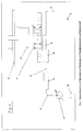
- a hydraulic system is shown in the measures to reduce pressure pulsations and structure-borne noise are implemented.
- the hydraulic medium like for example hydraulic oil, promoted by means of a hydraulic pump 31. Due to the non-uniform flow rate of the hydraulic pump and the resulting pressure pulsations become the walls of the hydraulic system is excited to vibrate. Hereby there is an emission of airborne sound and thus one noisy environment.
- the illustrated Hydraulic system through the walls of the pipe 33 the pulsation of the liquid flow is excited to vibrate. Furthermore, vibrations in the hydraulic pump 31 itself arise, transferred.
- the flow pulsation should be smoothed out.
- a pulsation reducer 35 for example as an expansion hose or as a storage element is carried out, as at the beginning with reference to various European Patent specifications explained.
- Fig. 1st a Insulation of structure-borne noise to ensure what is shown in Fig. 1st is referred to as device 39.
- this device as shown downstream to integrate the insulation of liquid pulsations is because the walls otherwise due to pressure pulsations of the system are excited to vibrate again, resulting in a Structure-borne noise.
- this Device 39 for the insulation of structure-borne noise are the following Pipelines 40 and 42 almost free of vibrations or Structure-borne sound waves, which is also a consumption example 4/3-way valve 41 and the synchronous cylinder 43 free of Structure-borne noise.
- the hydraulic medium is in the final pipeline 45 again the reservoir 29 fed.
- Fig. 2 is now one for the purpose of structure-borne sound insulation developed device shown in longitudinal section.
- Structure-borne noise insulation is essentially through a perfect Separation of the metallic surfaces of the pipes, for example 1 and 6 achieved with the help of an intermediate medium 3.
- the tube 1 transmits the vibrations generated on the pump 31 (Structure-borne noise).
- the intermediate medium 3 preferably has a very much lower density than the pipe material. By the difference in density from tube 1 and intermediate medium 3 are the incoming Sound waves are largely reflected at their interface and only passed on to a small extent through the intermediate medium 3. Added to this is the damping property (absorption) of the intermediate medium, which is preferably to be executed soft, whereby additional sound energy is dissipated.
- the interface between the intermediate medium 3 and the tube 6 are used for reflection of sound waves that are transmitted in the intermediate medium.
- the intermediate medium can result from the shape of the pipe ends not be ousted. It arises at the dividing surfaces 13, 14, 15 and 16 an additional pressing of the intermediate medium and the pipe ends that support the sealing function.
- the level of structure-borne noise insulation significantly from the insulation of the liquid pulsations may depend on the poor insulation of the liquid pulsation to structure-borne noise in the system downstream of the Structure-borne noise insulation can result.
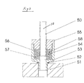
- FIG. 3 shows a further embodiment variant of a decoupling device, which in a pump housing for decoupling the vibrations and / or on a downstream of the pulsation damper Consumer can be screwed in.
- 3 are the pump housing or the consumer through the flange 51 represents.
- the most important aspects regarding the function of the decoupling element are also met here. How even in the element shown in Fig. 2, the perfect Separation of the metallic surfaces achieved.
- the end of the tube 50 in turn has a projection, which by a disc 54 is formed, which by a welding or Solder connection is firmly connected to the tube 50.
- This version of the pipe end is more technically feasible.
- the sealing function is also supported here. Will that be Pressurized fluid-carrying line 20, so it will rubber-elastic intermediate medium, formed by a disc-shaped Element 57, displaced radially outwards.
- the intermediate medium prevented a radial flow movement, and it builds up the annular nose on a surface pressure, which the Sealing function supports.
- the intermediate medium area 56 also designed as an annular element 56, which is axially pressed by the deformation of the ring 57 and its possible flow movement through this compression in the radial direction (towards the pipe axis) also through the nose-shaped design of the discs is additionally hindered. This also leads to an increased surface pressure of the intermediate medium on the disc-shaped projection 54 and one Nut 55, which supports the sealing function.
- the socket 53 is screwed into the flange 51, which annular housing 52 of the seal of this screw serves. This is when screwing pipes in steering gear and pump of a power steering state of the art.
- FIG. 4 shows a graphic for demonstrating the function of a decoupling element, for example shown in FIG. 2.
- Two measurements are shown, which were determined in a system which corresponds to that in FIG. 1.
- the acceleration of the pipe wall perpendicular to the pipe axis ie in the radial direction of the pipe cross-section, was measured with piezoelectric accelerometers.
- the first measuring point is in the pipe section 33, and here the signal a 1 was recorded.
- the second measuring point lies in the pipe section 40, and here the signal a 2 was recorded.
- the dotted line 61 shows the transfer function of an expansion hose 35 without a decoupling element 39 connected downstream. It can be seen that the transfer function is even higher than 1 (or 0 dB) and consequently the vibrations in the pipeline section 39 are stronger than in section 33. This is an indication that the expansion hose, although its good reduction in pressure pulsations, is the transmission of structure-borne noise not prevented.
- the solid curve 63 shows the same transfer function for the system in which the decoupling element 39 was connected downstream of the expansion hose 35. There is a significant reduction in pipe vibration in section 40 (a 1 ) compared to section 33 (a 2 ).
- FIGS. 2 and 3 act it is of course only examples to explain the present invention. It goes without saying that the interrupted pipeline is also a plastic line, however, the problem of structure-borne noise transmission can be less serious in plastic pipes.
- the interpretation the device in the case of using, for example reinforced plastic pipes is similar to those shown in Figs. 2 and 3, again by an intermediate medium is selected whose density is less than the density of the polymer material from which the pipeline is made is.
- the envelope encompassing the device on the outside or the ring-shaped connection socket 53 does not necessarily have to be made of metal be made, but also for example reinforced polymer material can be used.
- Disposable items can be the sleeve or the nut during assembly the intermediate medium can be arranged in a pressing manner, for example by means of shrinking, pressing or injection molding technology.
- the screws shown can also be rivets, for example are used, as well as other assembly elements.
- Suitable damping materials are certainly NBR Rubber, silicones, polyurethanes and other thermoplastic or thermosetting elastomers in question, but it is clear that the material used meets the required criterion which should have a lower density and be flexible. At a possible series production, there are many other factors, such as. Temperature and abrasion resistance, a role play, as a matter of course also the applicability by means of simplest manufacturing technology.
- instead of two or more intermediate rings are arranged from an intermediate ring be, of course also an execution without intermediate ring is quite conceivable, such as in Fig. 3 shown.
Landscapes
- Engineering & Computer Science (AREA)
- General Engineering & Computer Science (AREA)
- Mechanical Engineering (AREA)
- Pipe Accessories (AREA)
Priority Applications (4)
| Application Number | Priority Date | Filing Date | Title |
|---|---|---|---|
| EP99121112A EP1094267A1 (fr) | 1999-10-22 | 1999-10-22 | Dispositif pour atténuer le son structurel dans tuyauteries |
| AU76381/00A AU7638100A (en) | 1999-10-22 | 2000-10-17 | Device for reducing structure-borne noises in conduits |
| PCT/CH2000/000557 WO2001031248A1 (fr) | 1999-10-22 | 2000-10-17 | Dispositif pour la reduction des bruits transmis par conduction dans des conduites |
| EP00965711A EP1222422A1 (fr) | 1999-10-22 | 2000-10-17 | Dispositif pour la reduction des bruits transmis par conduction dans des conduites |
Applications Claiming Priority (1)
| Application Number | Priority Date | Filing Date | Title |
|---|---|---|---|
| EP99121112A EP1094267A1 (fr) | 1999-10-22 | 1999-10-22 | Dispositif pour atténuer le son structurel dans tuyauteries |
Publications (1)
| Publication Number | Publication Date |
|---|---|
| EP1094267A1 true EP1094267A1 (fr) | 2001-04-25 |
Family
ID=8239262
Family Applications (2)
| Application Number | Title | Priority Date | Filing Date |
|---|---|---|---|
| EP99121112A Withdrawn EP1094267A1 (fr) | 1999-10-22 | 1999-10-22 | Dispositif pour atténuer le son structurel dans tuyauteries |
| EP00965711A Withdrawn EP1222422A1 (fr) | 1999-10-22 | 2000-10-17 | Dispositif pour la reduction des bruits transmis par conduction dans des conduites |
Family Applications After (1)
| Application Number | Title | Priority Date | Filing Date |
|---|---|---|---|
| EP00965711A Withdrawn EP1222422A1 (fr) | 1999-10-22 | 2000-10-17 | Dispositif pour la reduction des bruits transmis par conduction dans des conduites |
Country Status (3)
| Country | Link |
|---|---|
| EP (2) | EP1094267A1 (fr) |
| AU (1) | AU7638100A (fr) |
| WO (1) | WO2001031248A1 (fr) |
Cited By (4)
| Publication number | Priority date | Publication date | Assignee | Title |
|---|---|---|---|---|
| DE102007026842A1 (de) * | 2007-06-06 | 2008-12-11 | Endress + Hauser Wetzer Gmbh + Co Kg | Vorrichtung zur Bestimmung und/oder Überwachung einer Messgröße |
| WO2019077940A1 (fr) * | 2017-10-18 | 2019-04-25 | 株式会社デンソー | Raccord |
| JP2019074204A (ja) * | 2017-10-18 | 2019-05-16 | 株式会社デンソー | ジョイント |
| EP3670991A1 (fr) * | 2018-12-17 | 2020-06-24 | Bombardier Inc. | Système de couplage de conduit |
Families Citing this family (1)
| Publication number | Priority date | Publication date | Assignee | Title |
|---|---|---|---|---|
| DE202014102958U1 (de) * | 2014-06-30 | 2015-10-01 | Rehau Ag + Co | Rohrformteil |
Citations (5)
| Publication number | Priority date | Publication date | Assignee | Title |
|---|---|---|---|---|
| FR957514A (fr) * | 1950-02-23 | |||
| US2504634A (en) * | 1941-11-17 | 1950-04-18 | Pirelli | Sound and vibrationproof joint for metal tubing |
| GB2016628A (en) * | 1978-02-25 | 1979-09-26 | Karlsruhe Augsburg Iweka | Compensator |
| DE3515768A1 (de) * | 1985-05-02 | 1986-11-06 | Alfred Teves Gmbh, 6000 Frankfurt | Hochdruckdichte, metallische rohrverbindung |
| JPS62151640A (ja) * | 1985-12-26 | 1987-07-06 | Toshiba Corp | 制振装置 |
-
1999
- 1999-10-22 EP EP99121112A patent/EP1094267A1/fr not_active Withdrawn
-
2000
- 2000-10-17 AU AU76381/00A patent/AU7638100A/en not_active Abandoned
- 2000-10-17 WO PCT/CH2000/000557 patent/WO2001031248A1/fr not_active Ceased
- 2000-10-17 EP EP00965711A patent/EP1222422A1/fr not_active Withdrawn
Patent Citations (5)
| Publication number | Priority date | Publication date | Assignee | Title |
|---|---|---|---|---|
| FR957514A (fr) * | 1950-02-23 | |||
| US2504634A (en) * | 1941-11-17 | 1950-04-18 | Pirelli | Sound and vibrationproof joint for metal tubing |
| GB2016628A (en) * | 1978-02-25 | 1979-09-26 | Karlsruhe Augsburg Iweka | Compensator |
| DE3515768A1 (de) * | 1985-05-02 | 1986-11-06 | Alfred Teves Gmbh, 6000 Frankfurt | Hochdruckdichte, metallische rohrverbindung |
| JPS62151640A (ja) * | 1985-12-26 | 1987-07-06 | Toshiba Corp | 制振装置 |
Non-Patent Citations (1)
| Title |
|---|
| PATENT ABSTRACTS OF JAPAN vol. 011, no. 380 (M - 650) 11 December 1987 (1987-12-11) * |
Cited By (7)
| Publication number | Priority date | Publication date | Assignee | Title |
|---|---|---|---|---|
| DE102007026842A1 (de) * | 2007-06-06 | 2008-12-11 | Endress + Hauser Wetzer Gmbh + Co Kg | Vorrichtung zur Bestimmung und/oder Überwachung einer Messgröße |
| US8534912B2 (en) | 2007-06-06 | 2013-09-17 | Endress + Hauser Wetzer Gmbh + Co. Kg | Apparatus for determining and/or monitoring a measured variable |
| WO2019077940A1 (fr) * | 2017-10-18 | 2019-04-25 | 株式会社デンソー | Raccord |
| JP2019074204A (ja) * | 2017-10-18 | 2019-05-16 | 株式会社デンソー | ジョイント |
| JP7135601B2 (ja) | 2017-10-18 | 2022-09-13 | 株式会社デンソー | ジョイント |
| EP3670991A1 (fr) * | 2018-12-17 | 2020-06-24 | Bombardier Inc. | Système de couplage de conduit |
| US11248727B2 (en) * | 2018-12-17 | 2022-02-15 | Bombardier Inc. | Duct coupling system |
Also Published As
| Publication number | Publication date |
|---|---|
| AU7638100A (en) | 2001-05-08 |
| WO2001031248A1 (fr) | 2001-05-03 |
| EP1222422A1 (fr) | 2002-07-17 |
Similar Documents
| Publication | Publication Date | Title |
|---|---|---|
| EP3227152B1 (fr) | Étouffoir de modification de pression pour un système de freins hydraulique, et système de freins correspondant | |
| DE2106359A1 (de) | Anordnung eines Schalldämpfers an einem Kompressor | |
| DE102010033811B4 (de) | Hydraulisch dämpfende Hydro-Lager für Achslenkerlager | |
| DE4042201C1 (fr) | ||
| DE102018203450A1 (de) | Dichtungsanordnung und Fluidregelventil | |
| DE102006049594A1 (de) | Flanschverbindung für Rohrleitungen | |
| EP1384935A1 (fr) | Pièce flexible de raccordement de tuyaux, en matériau déformable élastiquement | |
| EP1537352B1 (fr) | Dispositif de raccordement tres etanche | |
| EP0237758A2 (fr) | Joint d'étanchéité | |
| EP1094267A1 (fr) | Dispositif pour atténuer le son structurel dans tuyauteries | |
| DE102011119513A1 (de) | Rohrverbindung zur fluiddichten Anbindung von Komponenten einer Klimaanlage | |
| DE3421604C2 (de) | Anordnung einer Schlauchhülse an einem Kanalkörper eines Fluidaggregates | |
| DE102011002491A1 (de) | Radialwellendichtring | |
| EP1398554B1 (fr) | Tuyau flexible et son procédé de fabrication | |
| EP0842357B1 (fr) | Garniture d'etancheite statique pour moteurs a combustion interne, notamment couvercle de fermeture pour carter de vilebrequin et de boite | |
| EP2841887A1 (fr) | Tube de mesure pour un débitmètre | |
| EP2982896A1 (fr) | Dispositif de fixation de tube insonorisant | |
| DE102010003674A1 (de) | Ringförmiges Dichtelement | |
| DE102016012297A1 (de) | Stahlbetonbauwerk | |
| WO2003058107A1 (fr) | Dispositif d'etancheite | |
| EP1918626A1 (fr) | Accumulateur pour l'amortissement de pulsations de pression | |
| DE202012013675U1 (de) | Vorrichtung zum Abdichten eines Ringraumes zwischen einem Medienrohr/Kabel und einer Kernbohrung/Schutzrohr | |
| DE19943473B4 (de) | Dichtungsvorrichtung | |
| EP2360388B1 (fr) | Ressort multicouche doté d'une couche élastomère sinueuse | |
| DE112007001156B4 (de) | Strömungselement für ein hydraulisches System |
Legal Events
| Date | Code | Title | Description |
|---|---|---|---|
| PUAI | Public reference made under article 153(3) epc to a published international application that has entered the european phase |
Free format text: ORIGINAL CODE: 0009012 |
|
| AK | Designated contracting states |
Kind code of ref document: A1 Designated state(s): AT BE CH CY DE DK ES FI FR GB GR IE IT LI LU MC NL PT SE |
|
| AX | Request for extension of the european patent |
Free format text: AL;LT;LV;MK;RO;SI |
|
| AKX | Designation fees paid | ||
| REG | Reference to a national code |
Ref country code: DE Ref legal event code: 8566 |
|
| STAA | Information on the status of an ep patent application or granted ep patent |
Free format text: STATUS: THE APPLICATION IS DEEMED TO BE WITHDRAWN |
|
| 18D | Application deemed to be withdrawn |
Effective date: 20011026 |