EP1094479A2 - Dispositif pour l' actionnement de circuits - Google Patents
Dispositif pour l' actionnement de circuits Download PDFInfo
- Publication number
- EP1094479A2 EP1094479A2 EP00118986A EP00118986A EP1094479A2 EP 1094479 A2 EP1094479 A2 EP 1094479A2 EP 00118986 A EP00118986 A EP 00118986A EP 00118986 A EP00118986 A EP 00118986A EP 1094479 A2 EP1094479 A2 EP 1094479A2
- Authority
- EP
- European Patent Office
- Prior art keywords
- ratchet
- double
- shaft
- drive shaft
- pawl
- Prior art date
- Legal status (The legal status is an assumption and is not a legal conclusion. Google has not performed a legal analysis and makes no representation as to the accuracy of the status listed.)
- Granted
Links
- 230000033001 locomotion Effects 0.000 claims description 17
- 230000007935 neutral effect Effects 0.000 claims description 8
- 230000005540 biological transmission Effects 0.000 claims description 4
- 230000002265 prevention Effects 0.000 claims description 4
- 230000009471 action Effects 0.000 claims description 3
- 230000007480 spreading Effects 0.000 claims description 3
- 238000003892 spreading Methods 0.000 claims description 3
- 239000010902 straw Substances 0.000 claims 1
- 230000008901 benefit Effects 0.000 description 6
- 238000011161 development Methods 0.000 description 5
- 230000002441 reversible effect Effects 0.000 description 5
- 230000008859 change Effects 0.000 description 3
- 230000000903 blocking effect Effects 0.000 description 2
- 230000008878 coupling Effects 0.000 description 2
- 238000010168 coupling process Methods 0.000 description 2
- 238000005859 coupling reaction Methods 0.000 description 2
- 238000013461 design Methods 0.000 description 2
- 230000000694 effects Effects 0.000 description 2
- 238000000034 method Methods 0.000 description 2
- 230000008569 process Effects 0.000 description 2
- 238000005096 rolling process Methods 0.000 description 2
- 210000002023 somite Anatomy 0.000 description 2
- 125000006850 spacer group Chemical group 0.000 description 2
- 238000012360 testing method Methods 0.000 description 2
- 238000013519 translation Methods 0.000 description 2
- 230000009286 beneficial effect Effects 0.000 description 1
- 238000010586 diagram Methods 0.000 description 1
- 230000005489 elastic deformation Effects 0.000 description 1
- 230000001771 impaired effect Effects 0.000 description 1
- 238000009434 installation Methods 0.000 description 1
- 230000003993 interaction Effects 0.000 description 1
- 238000004519 manufacturing process Methods 0.000 description 1
- ORQBXQOJMQIAOY-UHFFFAOYSA-N nobelium Chemical compound [No] ORQBXQOJMQIAOY-UHFFFAOYSA-N 0.000 description 1
- 230000009467 reduction Effects 0.000 description 1
- 230000035939 shock Effects 0.000 description 1
- 239000007787 solid Substances 0.000 description 1
- 230000001550 time effect Effects 0.000 description 1
Images


Classifications
-
- H—ELECTRICITY
- H01—ELECTRIC ELEMENTS
- H01H—ELECTRIC SWITCHES; RELAYS; SELECTORS; EMERGENCY PROTECTIVE DEVICES
- H01H3/00—Mechanisms for operating contacts
- H01H3/32—Driving mechanisms, i.e. for transmitting driving force to the contacts
- H01H3/34—Driving mechanisms, i.e. for transmitting driving force to the contacts using ratchet
-
- H—ELECTRICITY
- H01—ELECTRIC ELEMENTS
- H01H—ELECTRIC SWITCHES; RELAYS; SELECTORS; EMERGENCY PROTECTIVE DEVICES
- H01H3/00—Mechanisms for operating contacts
- H01H3/22—Power arrangements internal to the switch for operating the driving mechanism
- H01H3/30—Power arrangements internal to the switch for operating the driving mechanism using spring motor
- H01H3/3005—Charging means
- H01H3/3021—Charging means using unidirectional coupling
-
- H—ELECTRICITY
- H01—ELECTRIC ELEMENTS
- H01H—ELECTRIC SWITCHES; RELAYS; SELECTORS; EMERGENCY PROTECTIVE DEVICES
- H01H3/00—Mechanisms for operating contacts
- H01H3/22—Power arrangements internal to the switch for operating the driving mechanism
- H01H3/30—Power arrangements internal to the switch for operating the driving mechanism using spring motor
- H01H3/3047—Power arrangements internal to the switch for operating the driving mechanism using spring motor adapted for operation of a three-position switch, e.g. on-off-earth
Definitions
- the invention is based on an actuating device, in particular for actuating current paths, with a Actuating shaft actuating current path, with at least one with the actuating shaft via a gearbox coupled drive shaft driven by a drive, the drive being connected to the drive shaft standing manually operated crank and / or Drive motor can be.
- actuators for electrical switchgear such as low, medium or high voltage switchgear
- Usual translation ratios of such Gearboxes are at least 1: 400 and range up to approx. 1: 2000, for manual operation approx. 1: 5 to 1: 100.
- the switching process of such a Switchgear under one and up to several seconds Claim.
- the present invention is therefore based on the object to propose an actuator, which is an extremely simple and therefore inexpensive has reversible gear.
- an actuator which is an extremely simple and therefore inexpensive has reversible gear.
- the Disadvantages of the prior art described above be remedied.
- an actuator of proposed type described in the introduction which provides that the gearbox has at least one ratchet wheel with a Pawl gear teeth and at least two double pawls having reversible ratchet gear is that on the actuating shaft the at least one ratchet wheel is rotatably arranged that the drive shaft as Eccentric shaft formed with preferably two eccentrics is that on the preferably two eccentrics one each Double pawl limitedly non-rotatable by means of a friction clutch is arranged that the double pawls two by one Spreading angle spread ratchet arms that the Pawl arms on the side facing away from the drive shaft one each in the ratchet gear teeth of the ratchet wheel engaging designed latch tip that at rotating drive shaft one pawl tip in Engagement with the ratchet gear teeth and that the Double pawl movement with the drive shaft rotating leading leadership elements are in place.
- the object of the invention has the advantage on that such a ratchet gearbox in manufacture and Assembly is very inexpensive.
- the ratchet gear teeth two opposing rows of teeth to accommodate the respective in the ratchet gear teeth engaging latch tips, the two Rows of teeth can also overlap.
- the pawl intervention is a left or right turn of the Actuating shaft generated.
- the overlap areas of the Rows of teeth must act on both sides of the teeth be designed.
- the two eccentrics on the drive shaft preferably around are offset from each other by an angle of 1800. This turns on when the drive shaft rotates Uniform engagement and lifting of the pawl tips of the two double pawls reached.
- Double jacks designed symmetrically. Besides, that is Tooth pitch of the ratchet gear teeth is slightly smaller than twice the eccentricity of the Eccentric center to the central axis of the drive shaft. It is assumed that only one ratchet wheel is on the actuating shaft is present, or two identical, aligned ratchet wheel discs.
- a particularly preferred development of the invention is characterized by the fact that the two double pawls are so asymmetrical that the tooth pitch of the ratchet wheel slightly smaller than four times the Eccentricity of the eccentric center to the central axis the drive shaft is.
- Such an asymmetrical Double jack has a short and a long half of the jack on. The difference is advantageously one short to a long handle half a little more than that Half the tooth pitch of the ratchet wheel.
- Another development of the invention provides that the actuating shaft two arranged parallel to each other Pawls are available, with a double pawl on each the at least one drive shaft for engagement in each Ratchet wheel is provided.
- the two Pawls are identical and either offset to each other or in alignment on the one operating shaft are arranged.
- a preferred embodiment of the invention provides before that the two double pawls are symmetrical are that the rows of teeth of the ratchet gear teeth two ratchet wheels offset by half a tooth pitch are arranged and that the tooth pitch of the two Ratchet wheels slightly smaller than four times the Eccentricity of the eccentric center to the central axis the drive shaft is.
- Such an embodiment has the Advantage on that due to the offset to each other arranged ratchet wheels with symmetrical double ratchets the tooth pitch is not less than twice, but slightly less than four times the eccentricity of the eccentric center to the central axis of the drive shaft is. Due to such a tooth division, the teeth of the Ratchet wheel much more stable, which is particularly the case with double - sided application of the individual teeth of is crucial.
- Another preferred embodiment of the invention provides before that the the actuator for Three-position switch is executed and one the current path closing, one separating the current path and one the Current path with switching connection connecting earth.
- Three-position switches have the advantage that only one moving switching element two switching functions exercises.
- three-position switches are space and space-saving and therefore inexpensive. They also point out the advantage that the earth function does not Switching capacity required. Because a three position switch an either / or switch is also not Locking the individual switch positions against each other required.
- the three position switch in neutral position Actuating shaft that separates the current path after that Angle of rotation of the actuating shaft of about 90 ° in one Direction of rotation closed the current path and from about 90 ° in the other direction the current path is connected to earth.
- Such an arrangement of the three-position switch has proven to be particularly advantageous in practice.
- At least two independently drivable Drive shafts with eccentrics arranged on them There are double jacks, through which the Actuating shaft in the different switching positions can be actuated. Because of the two independently drivable drive shafts is a unique assignment reached a drive shaft to a switching position. On Switch through the actuating device in all three Switch positions by turning only one The drive shaft is therefore excluded.
- the three-position switch actuator have the ratchet wheels or Ratchet wheel only one tooth row section each Engagement of the double pawls of the respective actuated Drive axle on so that a rotation of those Drive shaft in their engagement area the ratchet wheels or the ratchet wheel is not, or is, without actuation the actuating shaft is freely rotatable. This will avoided that when actuating one drive shaft, due to the actuation of the other drive shaft Collision or a blocking state in the Actuator is possible.
- the Three-position switch actuator is provided that by rotating a drive shaft Actuating shaft only rotated by a little more than 90 ° and can be turned back.
- a drive shaft Actuating shaft only rotated by a little more than 90 ° and can be turned back.
- one further rotation of the corresponding drive shaft Actuating shaft no longer twisted.
- An embodiment of the invention provides that the to Drive shafts existing double pawls each in various arranged on the actuating shaft Engage ratchet wheels. This can then advantageously be the case when four on the actuating shaft Pawls are available, two each Ratchet wheels offset by half a tooth pitch are arranged to each other and for engagement of each serve two double pawls on a drive shaft.
- the three-position switch actuating device grab the drive shafts existing double jacks only in one on the Actuating shaft on ratchet wheel.
- a ratchet wheel and two each on the two drive shafts Double pawls sit which are asymmetrical and each have a long and a short latch arm.
- the ratchet gear teeth a Ratchet different ratchet toothing sections with at least partially different rows of teeth for Engagement of the respective pawl tips of the corresponding Has double pawls.
- Such Ratchet gear sections are especially then necessary if several on one ratchet wheel, independently double pawls which can be driven from one another come into engagement.
- a variant of the invention provides that the teeth of the Rows of teeth from only one side of a latch tip be applied, a beveled rear flank exhibit. On such a rear flank, the Jack tip run off well without the actuation shaft actuated or the tip of the jack is damaged.
- Another preferred embodiment of the invention is characterized by the fact that the teeth of the rows of teeth, which are acted upon by latch tips from both sides be one on both sides, especially to the Ratchet wheel circumference approximately rectangular, Attack surface to act on the latch tips exhibit.
- Such a configuration of the corresponding Teeth has proven to be particularly stable and therefore beneficial proven.
- Another embodiment of the invention provides that the guide elements on the double pawls on or molded with corresponding rigid counter bearings are corresponding cam tracks.
- the friction clutches can double pawls due to their small friction torque only then in the correct sequence to intervene on the desired page and to leave the unwanted page bring if the pivoting movements of the double pawls are not be hindered by external moments on the ratchet wheel. If, for example, one turns in the course of an operation Drive shaft the direction of rotation of the drive shaft, see above could be the last intervening or pushing Jack half of a double jack still in one with high friction between the tip of the latch and the engaging tooth accompanying intervention while the opposite working half with the double pawl already, in opposite direction. It would thus an absolute blocking situation of the Enter the actuator.
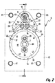
- the actuating device 6 has a one Actuator shaft 7 driving current path, on the a free end a lever 8 for the transmission of motion is arranged on a switching device.
- the actuating shaft 7 is via a ratchet gear with a drive shaft 9 coupled.
- the drive shaft 9 becomes, as in FIG. 3 is clearly recognizable from a manually operated Hand crank 11 driven. According to the invention, however it can also be provided that in addition to the hand crank 11 a drive motor is present.
- the drive shaft 9 is designed as an eccentric shaft with two eccentrics 12 and 13.
- the two eccentrics 12 and 13 are at an angle from 1800 offset from each other and are each by means of pins 16 and 17 with the drive shaft 9 non-rotatably connected.
- the double pawls 18 and 19 have two by one Spreading angle spread latch arms 26, 27, 28 and 29 on, the latch arms 26, 27, 28 and 29 on the Drive shaft 9 facing away from each one Have pawl tip 31.
- a friction clutch between the double pawls 18 and 19 and the eccentrics 12 and 13 is therefore necessary to ensure that e.g. B. with a right turn Drive shaft 9 actually the right latch arms 27th and 29 come into engagement with the ratchet wheels 32 and 33 and thus generates a right-hand drive torque becomes.
- This requires a frictional connection via the friction clutches be generated. Otherwise, this frictional connection must unstable behavior of the double pawls 18 and 19 on the Stabilize eccentrics 12 and 13 so far that a uncontrolled influence by the mass of the Double jacks 18 and 19 is excluded.
- the drive shaft 9 and the actuating shaft 7 is by means of locking washers 63 on the housing wall 56 and 57 secured.
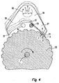
- FIG Actuating device 71 is shown namely for a three-position switch that has a branch 72 with a busbar 73 or with an earth contact 74 connects. It must be provided that each of the two switching operations by hand from their own, distinctive drive device can. In addition, an inadmissible must Switching through, e.g. B. from the disconnector ON position to the middle position disconnect switch OFF Earth ON must be prevented.
- FIG. 5 a representation is chosen in FIG. 5 as would be the switching element 82 directly on the actuating shaft 81 attached. This will cause the actuation shaft to rotate 81 the isolating switch of the Three-position switch 71 closed and branch 72 connected to the busbar 73.
- the Actuating shaft 81 to the left by approx. 90 ° becomes the branch 72 connected to the earth contact 74.
- the total operating angle of the actuating shaft 81 is included this configuration at a little more than 180 ° and will generated by two actuators according to 2 and 3 with a modified toothing area equipped and on the common actuating shaft 81 be set.
- start and end positions suitably match each other, as shown in Fig. 5 is shown.
- the Drive shaft 84 are on the Drive shaft 84 also two double pawls 88 and 89 arranged one eccentric.
- the two left Ratchet wheels 78 and 79 are, corresponding to the ratchet wheels 76 and 77, also offset by half a tooth pitch on the Actuating shaft 81 arranged.
- the interlocking of the two Pawl wheels 78 and 79 is such that over a Rotating the drive shaft 84 around the actuating shaft 81 an angle of just a little more than 90 ° from the neutral middle position of the switching element 82 for Closing the circuit breaker, d. H. to connect the Switching elements 82 are rotated with the busbar 73 can.
- FIG. 6 another embodiment is one Actuator 96 according to the invention for a Three position switch shown.
- the three-position switch actuator 96 assigns, as in FIG. 6, well is recognizable, two drive shafts 98 and 99 with each a hand crank 101, the clockwise rotation of the Drive shaft 98 of the earth electrode switched on or by Turning to the left is switched off and turning to the right Drive shaft 99 of the isolator switched on or at Left turn is turned off.
- 6 is also a position indicator 102 on an actuating shaft 103 in switch disconnector OFF, earth electrode OFF shown.
- the switching element 102 on the Switch position switch ON set.
- One with the Actuating shaft 103 connected via the drive lever 105 Linkage 110 leads to the switching elements to be actuated.
- FIG. 9 is a section of the three-part switch 96 7 along the line A-B.
- Ratchet wheel 107 with the associated Pawl gear teeth clearly visible.
- Ratchet gear teeth of ratchet wheel 104 or the two Ratchet wheel discs 107 and 108 are described in the description of Fig. 11 discussed in more detail.
- Fig. 10 which is a section through the Fig. 8 along the line C-D shows the double pawls 122 and 116 corresponding to the double pawls 123 and 117 designed
- the double pawls 122, 123 and 116, 117 offset on the side on the eccentric shaft 119 and Drive shaft 98 can be mounted.
- a maximum is advantageous Offset approximately 1.2 times a tooth pitch and in the catch-up position is a game with half the difference between tooth length and 4 times the eccentric stroke, thus a safe engagement of the double pawls 122, 123 and 116, 117 even under high loads and any associated elastic deformations even after a certain amount of wear is guaranteed.
- One revolution of the drive shaft 98 or 99 mediates a rotation of the actuating shaft 103, which corresponds to the angle of a tooth pitch. Due to the Use of long latch arms 126 and corresponding short ratchet arms 127 can offset the rows of teeth the ratchet wheel 104, as it is according to the embodiments 2 and 3 and FIG. 5 was avoided become.
- Advantage of that shown in FIGS. 6 to 10 Embodiment of the invention is that only one Ratchet wheel 104 for realizing a Three position switch actuator 96 is used becomes.
- the on Lead screws 129 run off.
- the guide screws 129 are for space reasons in on the double jacks 116, 117 and 122, 123 existing windows 131 arranged.
- a rocker arm 137 is clear in FIGS. 9 and 10 shown to avoid simultaneous intervention the double jacks 116, 117 and 122, 123 with simultaneous Actuation of the two drive shafts 98 and 99 provided is.
- the rocker arm 137 is rotatable about an axis 138 stored.
- the function of the rocker arm 137 is in the Description of the figures for Fig. 12 explained.
- the ratchet wheel 104 described in FIG. 11 leads to a Translation, with the 10 revolutions of the corresponding Drive shafts each slightly more than 90 ° Output angle of the actuating shaft is generated. Finer or coarser divisions with adjusted at the same time Eccentric strokes larger or smaller Generate gear ratios.
- Fig. 12 is the latch tip of the short latch arm the double pawl 123 engages with a tooth flank 154 the ratchet wheel disc 107.
- A can be clearly seen Rocker lever 137, which along the axis of rotation 138 between the short latch arms 127 of the two double jacks 123 and 116 is arranged.
- In the neutral middle position of the ratchet wheel discs 107 and 108 can be in the in Fig. 12 shown embodiment only the short Pawl arms 127 of the two double pawls 123 and 116 in Engage tooth flanks on ratchet wheel 107 or 108.
- the long ratchet arms 126 of the two double pawls 117 and 122 can due to lack of tooth flanks in their Thrust positions not in the ratchet teeth of the Ratchet wheel discs 107 and 108 engage and can thus no rotation of the two ratchet wheel disks 107 or 108 cause. For this reason, a rocker arm 137 is sufficient Avoidance of simultaneous intervention by the Double jacks 116 and 126 between the short jack arms 127 of the two double pawls 116 and 123.
- Pins 155 are provided on the short latch arms 126, which cooperate with the rocker arm 137 such that due to the respective rocker arm position only one Pawl arm for engagement on ratchet wheel disc 107 or 108 can come.
- the rocker arm 137 leaves one Either-or-intervention too. This prevention of intervention is only in the exact middle position Actuator 96 required. Basically must namely in this middle position alternatively Disconnect switch or the earthing switch are operated can.
Landscapes
- Transmission Devices (AREA)
- Connection Of Motors, Electrical Generators, Mechanical Devices, And The Like (AREA)
- Lock And Its Accessories (AREA)
- Multiple-Way Valves (AREA)
Applications Claiming Priority (2)
| Application Number | Priority Date | Filing Date | Title |
|---|---|---|---|
| DE19951130 | 1999-10-23 | ||
| DE19951130A DE19951130B4 (de) | 1999-10-23 | 1999-10-23 | Betätigungseinrichtung zur Betätigung von Strombahnen |
Publications (3)
| Publication Number | Publication Date |
|---|---|
| EP1094479A2 true EP1094479A2 (fr) | 2001-04-25 |
| EP1094479A3 EP1094479A3 (fr) | 2002-12-11 |
| EP1094479B1 EP1094479B1 (fr) | 2009-04-29 |
Family
ID=7926663
Family Applications (1)
| Application Number | Title | Priority Date | Filing Date |
|---|---|---|---|
| EP00118986A Expired - Lifetime EP1094479B1 (fr) | 1999-10-23 | 2000-09-01 | Dispositif pour l' actionnement de circuits |
Country Status (3)
| Country | Link |
|---|---|
| EP (1) | EP1094479B1 (fr) |
| AT (1) | ATE430372T1 (fr) |
| DE (2) | DE19951130B4 (fr) |
Cited By (6)
| Publication number | Priority date | Publication date | Assignee | Title |
|---|---|---|---|---|
| CN102184800A (zh) * | 2011-01-07 | 2011-09-14 | 无锡市锡山湖光电器有限公司 | 用于真空断路器的复合棘轮 |
| EP2560178A1 (fr) * | 2011-08-19 | 2013-02-20 | Schneider Electric Sachsenwerk GmbH | Disjoncteur destiné à commuter une tension moyenne et procédé de fonctionnement d'un tel disjoncteur |
| DE202012103605U1 (de) | 2012-09-20 | 2014-01-07 | Allgäuer Überlandwerk GmbH | Mittelspannungs-Schalteinrichtung |
| DE102012108877A1 (de) | 2012-09-20 | 2014-03-20 | Allgäuer Überlandwerk GmbH | Mittelspannungs-Schalteinrichtung |
| WO2019077311A1 (fr) * | 2017-10-16 | 2019-04-25 | William Hackett Lifting Products Limited | Perfectionnements apportés ou se rapportant à des rochets |
| CN110161451A (zh) * | 2019-06-21 | 2019-08-23 | 国网福建省电力有限公司 | 接表座多表型仓储切换机构及其工作方法 |
Families Citing this family (1)
| Publication number | Priority date | Publication date | Assignee | Title |
|---|---|---|---|---|
| DE102011006277B4 (de) | 2011-03-28 | 2012-10-18 | Schneider Electric Sachsenwerk Gmbh | Einrichtung zur Betätigung von Strombahnen |
Citations (1)
| Publication number | Priority date | Publication date | Assignee | Title |
|---|---|---|---|---|
| US3475981A (en) | 1967-11-20 | 1969-11-04 | Powell Electric Mfg Co | Motor operator for load break switch |
Family Cites Families (2)
| Publication number | Priority date | Publication date | Assignee | Title |
|---|---|---|---|---|
| JPS59189519A (ja) * | 1983-04-12 | 1984-10-27 | 富士電機株式会社 | しや断器操作用蓄勢器の駆動装置 |
| DE19605711C2 (de) * | 1996-02-16 | 2000-03-16 | Alstom Sachsenwerk Gmbh | Antriebseinrichtung für ein Schaltgerät |
-
1999
- 1999-10-23 DE DE19951130A patent/DE19951130B4/de not_active Expired - Fee Related
-
2000
- 2000-09-01 DE DE50015632T patent/DE50015632D1/de not_active Expired - Lifetime
- 2000-09-01 AT AT00118986T patent/ATE430372T1/de not_active IP Right Cessation
- 2000-09-01 EP EP00118986A patent/EP1094479B1/fr not_active Expired - Lifetime
Patent Citations (1)
| Publication number | Priority date | Publication date | Assignee | Title |
|---|---|---|---|---|
| US3475981A (en) | 1967-11-20 | 1969-11-04 | Powell Electric Mfg Co | Motor operator for load break switch |
Cited By (8)
| Publication number | Priority date | Publication date | Assignee | Title |
|---|---|---|---|---|
| CN102184800A (zh) * | 2011-01-07 | 2011-09-14 | 无锡市锡山湖光电器有限公司 | 用于真空断路器的复合棘轮 |
| EP2560178A1 (fr) * | 2011-08-19 | 2013-02-20 | Schneider Electric Sachsenwerk GmbH | Disjoncteur destiné à commuter une tension moyenne et procédé de fonctionnement d'un tel disjoncteur |
| DE202012103605U1 (de) | 2012-09-20 | 2014-01-07 | Allgäuer Überlandwerk GmbH | Mittelspannungs-Schalteinrichtung |
| DE102012108877A1 (de) | 2012-09-20 | 2014-03-20 | Allgäuer Überlandwerk GmbH | Mittelspannungs-Schalteinrichtung |
| DE102012108877B4 (de) * | 2012-09-20 | 2015-01-08 | Allgäuer Überlandwerk GmbH | Mittelspannungs-Schalteinrichtung |
| WO2019077311A1 (fr) * | 2017-10-16 | 2019-04-25 | William Hackett Lifting Products Limited | Perfectionnements apportés ou se rapportant à des rochets |
| CN110161451A (zh) * | 2019-06-21 | 2019-08-23 | 国网福建省电力有限公司 | 接表座多表型仓储切换机构及其工作方法 |
| CN110161451B (zh) * | 2019-06-21 | 2024-03-12 | 国网福建省电力有限公司 | 接表座多表型仓储切换机构及其工作方法 |
Also Published As
| Publication number | Publication date |
|---|---|
| ATE430372T1 (de) | 2009-05-15 |
| EP1094479A3 (fr) | 2002-12-11 |
| DE50015632D1 (de) | 2009-06-10 |
| EP1094479B1 (fr) | 2009-04-29 |
| DE19951130A1 (de) | 2001-04-26 |
| DE19951130B4 (de) | 2005-09-15 |
Similar Documents
| Publication | Publication Date | Title |
|---|---|---|
| EP0907192B1 (fr) | Sélecteur de prises | |
| DE69936556T2 (de) | Steuergerät für die Entladung und Entkupplung eines Energieakkumulators während des Trennens eines trennbaren Schalters | |
| DE602005006077T2 (de) | Mechanische Steuervorrichtung für ein elektrisches Gerät mit drei Schaltstellungen mit einem Wahlhebel der mit eine Nocke wirkt | |
| DE69802617T2 (de) | Federkraftantrieb für ein Schaltgerät, insbesondere für einen Lastschalter | |
| DE19758078A1 (de) | Kraftfahrzeugtürverschluß | |
| WO2010149483A1 (fr) | Fenêtre d'inspection et borne de mise à la terre pour un ensemble haute tension | |
| DE1555932C3 (de) | Steuereinrichtung fur ein Wechsel getriebe fur Fahrzeuge | |
| DE102005055788A1 (de) | Betätigungseinrichtung für ein bewegliches Bauteil | |
| EP1094479A2 (fr) | Dispositif pour l' actionnement de circuits | |
| EP1633966B1 (fr) | Mecanisme de commande pour deplacement reversible d'un clapet de soupape | |
| EP0967350B1 (fr) | Dispositif de commande électromotrice pour serrure de véhicule automobile | |
| DE3812853C1 (fr) | ||
| AT403145B (de) | Antrieb für einen trennschalter, insbesondere für einen fahrleitungsschalter | |
| DE3610975A1 (de) | Drehantrieb mit einer drehmomentbegrenzungsvorrichtung | |
| EP0764751A1 (fr) | Positionneur à moteur électrique de véhicule | |
| EP0665361A1 (fr) | Interrupteur de fin de course d'un arbre | |
| EP2159358B1 (fr) | Verrou pour un composant destiné à la fermeture d'une ouverture | |
| DE2923019C2 (de) | Hochspannungsschalter | |
| DE673315C (de) | Federkraftspeicherantrieb fuer elektrische Leistungsschalter | |
| DE2216272C3 (de) | Hochspannungsschaltgerät, insbesondere Trennschalter | |
| DE9408501U1 (de) | Schloß für Türen oder Fenster | |
| DE2754212C2 (de) | Sprungschaltwerk für elektrische Federkontakte | |
| DE102011006277B4 (de) | Einrichtung zur Betätigung von Strombahnen | |
| DE3203956C2 (de) | Sprungantriebsvorrichtung für ein elektrisches Schaltgerät | |
| DE1505681C3 (fr) |
Legal Events
| Date | Code | Title | Description |
|---|---|---|---|
| PUAI | Public reference made under article 153(3) epc to a published international application that has entered the european phase |
Free format text: ORIGINAL CODE: 0009012 |
|
| AK | Designated contracting states |
Kind code of ref document: A2 Designated state(s): AT BE CH CY DE DK ES FI FR GB GR IE IT LI LU MC NL PT SE |
|
| AX | Request for extension of the european patent |
Free format text: AL;LT;LV;MK;RO;SI |
|
| PUAL | Search report despatched |
Free format text: ORIGINAL CODE: 0009013 |
|
| AK | Designated contracting states |
Kind code of ref document: A3 Designated state(s): AT BE CH CY DE DK ES FI FR GB GR IE IT LI LU MC NL PT SE |
|
| AX | Request for extension of the european patent |
Free format text: AL;LT;LV;MK;RO;SI |
|
| 17P | Request for examination filed |
Effective date: 20030204 |
|
| AKX | Designation fees paid |
Designated state(s): AT BE CH CY DE DK ES FI FR GB GR IE IT LI LU MC NL PT SE |
|
| RAP1 | Party data changed (applicant data changed or rights of an application transferred) |
Owner name: AREVA T&D SA |
|
| 17Q | First examination report despatched |
Effective date: 20061214 |
|
| GRAP | Despatch of communication of intention to grant a patent |
Free format text: ORIGINAL CODE: EPIDOSNIGR1 |
|
| GRAS | Grant fee paid |
Free format text: ORIGINAL CODE: EPIDOSNIGR3 |
|
| GRAA | (expected) grant |
Free format text: ORIGINAL CODE: 0009210 |
|
| AK | Designated contracting states |
Kind code of ref document: B1 Designated state(s): AT BE CH CY DE DK ES FI FR GB GR IE IT LI LU MC NL PT SE |
|
| REG | Reference to a national code |
Ref country code: GB Ref legal event code: FG4D Free format text: NOT ENGLISH |
|
| REG | Reference to a national code |
Ref country code: CH Ref legal event code: EP |
|
| REF | Corresponds to: |
Ref document number: 50015632 Country of ref document: DE Date of ref document: 20090610 Kind code of ref document: P |
|
| REG | Reference to a national code |
Ref country code: IE Ref legal event code: FG4D |
|
| REG | Reference to a national code |
Ref country code: CH Ref legal event code: NV Representative=s name: MICHELI & CIE SA |
|
| NLV1 | Nl: lapsed or annulled due to failure to fulfill the requirements of art. 29p and 29m of the patents act | ||
| PG25 | Lapsed in a contracting state [announced via postgrant information from national office to epo] |
Ref country code: PT Free format text: LAPSE BECAUSE OF FAILURE TO SUBMIT A TRANSLATION OF THE DESCRIPTION OR TO PAY THE FEE WITHIN THE PRESCRIBED TIME-LIMIT Effective date: 20090829 Ref country code: FI Free format text: LAPSE BECAUSE OF FAILURE TO SUBMIT A TRANSLATION OF THE DESCRIPTION OR TO PAY THE FEE WITHIN THE PRESCRIBED TIME-LIMIT Effective date: 20090429 Ref country code: ES Free format text: LAPSE BECAUSE OF FAILURE TO SUBMIT A TRANSLATION OF THE DESCRIPTION OR TO PAY THE FEE WITHIN THE PRESCRIBED TIME-LIMIT Effective date: 20090809 |
|
| PG25 | Lapsed in a contracting state [announced via postgrant information from national office to epo] |
Ref country code: SE Free format text: LAPSE BECAUSE OF FAILURE TO SUBMIT A TRANSLATION OF THE DESCRIPTION OR TO PAY THE FEE WITHIN THE PRESCRIBED TIME-LIMIT Effective date: 20090729 Ref country code: NL Free format text: LAPSE BECAUSE OF FAILURE TO SUBMIT A TRANSLATION OF THE DESCRIPTION OR TO PAY THE FEE WITHIN THE PRESCRIBED TIME-LIMIT Effective date: 20090429 |
|
| REG | Reference to a national code |
Ref country code: IE Ref legal event code: FD4D |
|
| PG25 | Lapsed in a contracting state [announced via postgrant information from national office to epo] |
Ref country code: DK Free format text: LAPSE BECAUSE OF FAILURE TO SUBMIT A TRANSLATION OF THE DESCRIPTION OR TO PAY THE FEE WITHIN THE PRESCRIBED TIME-LIMIT Effective date: 20090429 Ref country code: IE Free format text: LAPSE BECAUSE OF FAILURE TO SUBMIT A TRANSLATION OF THE DESCRIPTION OR TO PAY THE FEE WITHIN THE PRESCRIBED TIME-LIMIT Effective date: 20090429 |
|
| PLBE | No opposition filed within time limit |
Free format text: ORIGINAL CODE: 0009261 |
|
| STAA | Information on the status of an ep patent application or granted ep patent |
Free format text: STATUS: NO OPPOSITION FILED WITHIN TIME LIMIT |
|
| BERE | Be: lapsed |
Owner name: AREVA T&D SA Effective date: 20090930 |
|
| 26N | No opposition filed |
Effective date: 20100201 |
|
| PG25 | Lapsed in a contracting state [announced via postgrant information from national office to epo] |
Ref country code: MC Free format text: LAPSE BECAUSE OF NON-PAYMENT OF DUE FEES Effective date: 20090930 |
|
| GBPC | Gb: european patent ceased through non-payment of renewal fee |
Effective date: 20090901 |
|
| PG25 | Lapsed in a contracting state [announced via postgrant information from national office to epo] |
Ref country code: BE Free format text: LAPSE BECAUSE OF NON-PAYMENT OF DUE FEES Effective date: 20090930 |
|
| PG25 | Lapsed in a contracting state [announced via postgrant information from national office to epo] |
Ref country code: GR Free format text: LAPSE BECAUSE OF FAILURE TO SUBMIT A TRANSLATION OF THE DESCRIPTION OR TO PAY THE FEE WITHIN THE PRESCRIBED TIME-LIMIT Effective date: 20090730 |
|
| PG25 | Lapsed in a contracting state [announced via postgrant information from national office to epo] |
Ref country code: AT Free format text: LAPSE BECAUSE OF NON-PAYMENT OF DUE FEES Effective date: 20090901 Ref country code: GB Free format text: LAPSE BECAUSE OF NON-PAYMENT OF DUE FEES Effective date: 20090901 |
|
| PGFP | Annual fee paid to national office [announced via postgrant information from national office to epo] |
Ref country code: CH Payment date: 20101124 Year of fee payment: 11 |
|
| PG25 | Lapsed in a contracting state [announced via postgrant information from national office to epo] |
Ref country code: IT Free format text: LAPSE BECAUSE OF FAILURE TO SUBMIT A TRANSLATION OF THE DESCRIPTION OR TO PAY THE FEE WITHIN THE PRESCRIBED TIME-LIMIT Effective date: 20090429 |
|
| PG25 | Lapsed in a contracting state [announced via postgrant information from national office to epo] |
Ref country code: LU Free format text: LAPSE BECAUSE OF NON-PAYMENT OF DUE FEES Effective date: 20090901 |
|
| REG | Reference to a national code |
Ref country code: DE Ref legal event code: R084 Ref document number: 50015632 Country of ref document: DE |
|
| REG | Reference to a national code |
Ref country code: DE Ref legal event code: R084 Ref document number: 50015632 Country of ref document: DE Effective date: 20110730 |
|
| PG25 | Lapsed in a contracting state [announced via postgrant information from national office to epo] |
Ref country code: CY Free format text: LAPSE BECAUSE OF FAILURE TO SUBMIT A TRANSLATION OF THE DESCRIPTION OR TO PAY THE FEE WITHIN THE PRESCRIBED TIME-LIMIT Effective date: 20090429 |
|
| PGFP | Annual fee paid to national office [announced via postgrant information from national office to epo] |
Ref country code: FR Payment date: 20111005 Year of fee payment: 12 |
|
| REG | Reference to a national code |
Ref country code: DE Ref legal event code: R082 Ref document number: 50015632 Country of ref document: DE Representative=s name: DREISS PATENTANWAELTE, DE |
|
| REG | Reference to a national code |
Ref country code: DE Ref legal event code: R082 Ref document number: 50015632 Country of ref document: DE Representative=s name: DREISS PATENTANWAELTE PARTG MBB, DE Effective date: 20120116 Ref country code: DE Ref legal event code: R081 Ref document number: 50015632 Country of ref document: DE Owner name: SCHNEIDER ELECTRIC ENERGY FRANCE, FR Free format text: FORMER OWNER: AREVA T&D SA, PARIS, FR Effective date: 20120116 |
|
| REG | Reference to a national code |
Ref country code: CH Ref legal event code: PL |
|
| PG25 | Lapsed in a contracting state [announced via postgrant information from national office to epo] |
Ref country code: CH Free format text: LAPSE BECAUSE OF NON-PAYMENT OF DUE FEES Effective date: 20110930 Ref country code: LI Free format text: LAPSE BECAUSE OF NON-PAYMENT OF DUE FEES Effective date: 20110930 |
|
| REG | Reference to a national code |
Ref country code: FR Ref legal event code: TP Owner name: SCHNEIDER ELECTRIC ENERGY FRANCE, FR Effective date: 20120806 |
|
| REG | Reference to a national code |
Ref country code: FR Ref legal event code: ST Effective date: 20130531 |
|
| PG25 | Lapsed in a contracting state [announced via postgrant information from national office to epo] |
Ref country code: FR Free format text: LAPSE BECAUSE OF NON-PAYMENT OF DUE FEES Effective date: 20121001 |
|
| PGFP | Annual fee paid to national office [announced via postgrant information from national office to epo] |
Ref country code: DE Payment date: 20160701 Year of fee payment: 17 |
|
| REG | Reference to a national code |
Ref country code: DE Ref legal event code: R119 Ref document number: 50015632 Country of ref document: DE |
|
| PG25 | Lapsed in a contracting state [announced via postgrant information from national office to epo] |
Ref country code: DE Free format text: LAPSE BECAUSE OF NON-PAYMENT OF DUE FEES Effective date: 20180404 |