EP1094594B1 - Umrichter zur Regelung eines elektrischen Hubmotors - Google Patents
Umrichter zur Regelung eines elektrischen Hubmotors Download PDFInfo
- Publication number
- EP1094594B1 EP1094594B1 EP00402859A EP00402859A EP1094594B1 EP 1094594 B1 EP1094594 B1 EP 1094594B1 EP 00402859 A EP00402859 A EP 00402859A EP 00402859 A EP00402859 A EP 00402859A EP 1094594 B1 EP1094594 B1 EP 1094594B1
- Authority
- EP
- European Patent Office
- Prior art keywords
- torque
- motor
- speed
- variable speed
- speed drive
- Prior art date
- Legal status (The legal status is an assumption and is not a legal conclusion. Google has not performed a legal analysis and makes no representation as to the accuracy of the status listed.)
- Expired - Lifetime
Links
- 238000005259 measurement Methods 0.000 claims description 24
- 239000013598 vector Substances 0.000 claims description 14
- 238000000034 method Methods 0.000 claims description 3
- 230000000694 effects Effects 0.000 claims description 2
- 238000012544 monitoring process Methods 0.000 claims 5
- 238000005303 weighing Methods 0.000 claims 1
- 238000004804 winding Methods 0.000 description 4
- 238000004364 calculation method Methods 0.000 description 2
- 230000007423 decrease Effects 0.000 description 2
- 238000010586 diagram Methods 0.000 description 2
- 230000001133 acceleration Effects 0.000 description 1
- 239000003550 marker Substances 0.000 description 1
- 238000013178 mathematical model Methods 0.000 description 1
- 230000000087 stabilizing effect Effects 0.000 description 1
Images

Classifications
-
- H—ELECTRICITY
- H02—GENERATION; CONVERSION OR DISTRIBUTION OF ELECTRIC POWER
- H02P—CONTROL OR REGULATION OF ELECTRIC MOTORS, ELECTRIC GENERATORS OR DYNAMO-ELECTRIC CONVERTERS; CONTROLLING TRANSFORMERS, REACTORS OR CHOKE COILS
- H02P29/00—Arrangements for regulating or controlling electric motors, appropriate for both AC and DC motors
- H02P29/10—Arrangements for regulating or controlling electric motors, appropriate for both AC and DC motors for preventing overspeed or under speed
Definitions
- the present invention relates to a drive for controlling an electric hoisting motor, in particular a motor intended to equip a crane.
- Known drives ( DE-A-40 38981 ) comprise control means arranged to measure the engine torque at the beginning of its operation in order to determine, on the one hand, the weight of the load and, on the other hand, the permissible limit speed taking into account the available power.
- the engine torque is likely to vary following the increase of the winding radius on the drum.
- the torque measured at the beginning of the winding is lower than at the end of the winding and the power to be supplied to the motor can then exceed the maximum power available if the motor is running at a speed greater than its nominal speed.
- the cranes are provided with a load ring which is deformed according to the weight of the load and an associated electrical contact, provided that in case of deformation of the ring beyond a predetermined limit , the operation of the motor is interrupted.
- the usual practice is to hook various standard loads to the hook of the crane and to verify that the electrical contact changes state only from a predetermined weight.
- the invention aims to remedy at least one of the aforementioned drawbacks.
- the new variator according to the invention is of the type comprising control means for setting a set speed and control means for measuring the torque and the rotational speed of the motor, these control means being arranged to determine, from the torque measured, the speed limit of rotation of the engine, so as not to exceed a maximum available power.
- This variator is characterized in that the control means are arranged to perform, when the reference speed is greater than the nominal rotation speed of the motor, successive measurements of the torque, and in case of variation of the torque between two successive measurements. above a given threshold, determine the new speed limit.
- the invention ensured that the power required for the operation of the motor remains less than or equal to the maximum power of the drive and it avoids the triggering of a thermal circuit breaker.
- an initial torque measurement is performed by maintaining the motor at its rated speed for a predetermined time.
- measurements of the torque are made each time the rotation speed remains substantially constant above the nominal speed for a predetermined duration, preferably a duration of two to four seconds, more preferably three seconds. about.
- control means make the average, for a predetermined duration, preferably between one and three seconds, preferably still about two seconds, of the instantaneous torque .
- the new limit speed is calculated when the relative variation of the torque between two successive measurements exceeds 10%, preferably 15%.
- the torque of the motor is determined by vector analysis.
- the invention also relates to an assembly comprising a drive and an electromagnetic brake motor, the drive being arranged to release the brake at each engine launch.
- a drive 1 supplying a gear motor with electromagnetic brake 2, this motor being coupled to a drum 3 on which the hoisting rope 4 of a crane is wound.
- a charging ring 5 the function of which will be explained later, makes it possible to stop the operation of the engine 2 if the maximum authorized load is exceeded.
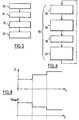
- the drive 1 is arranged to operate in two different modes, as will now be described, with reference to the figure 2 .
- step 20 power up, the drive asks the operator to enter an instruction on the selected operating mode.
- This instruction is analyzed in step 21, and the drive 1 passes either in a constant power operating mode shown schematically by the block 22, or in a torque controlled operating mode shown schematically by the block 23.
- the constant power operating mode is chosen during normal use of the crane, while the torque controlled operating mode is used for the calibration of the charge ring 5, as will be explained later.
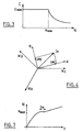
- the figure 3 represents the permissible torque as a function of the rotational speed of the motor.
- the engine torque C is less than or equal to a nominal value C NOM over a speed range between 0 and the nominal speed N NAME of the engine, as see him on the figure 3 . Then the maximum permissible torque C decreases as the speed N increases, the product of the torque by the speed being constant.
- the drive comprises control means, not shown in detail for the sake of clarity, comprising a lever 8 for example, allowing the operator to enter a set speed.
- the drive 1 is arranged to perform successive torque measurements when the set speed set by the operator is greater than the nominal speed N NOM , so as to cap the limit speed if necessary to a predetermined value, less than the speed of set and chosen so that the product of the torque by the speed of rotation remains lower than the product C NOM . NAME .
- the motor torque is determined, in a manner known per se, by a vector calculation whose principle is illustrated in FIG. figure 4 .
- the motor 2 is three-phase and the currents of each of the phases are sinusoidal quantities.
- the principle of vector measurement is to project the current vector I S into a rotating marker.
- This current vector I S corresponds to the vector sum of the current vectors x 1 , x 2 and x 3 of each of the phases.
- the components of the current vector I S are measured in a reference system of axes d and q rotating with respect to the vectors x 1 , x 2 and x 3 at the same frequency as the current vector.
- the reference d, q is chosen so that the components is d and is q of the current vector I s , projected on the axes d and q, respectively are proportional flow and torque.
- the drive In the constant power mode, the drive operates as follows.
- the drive 1 controls, in step 11, the unlocking of the electromagnetic brake and determines whether the requested reference speed is greater or less. no at nominal speed N NAME .
- the drive controls the operation of the motor without making a torque measurement.
- the drive goes into an operating mode shown schematically by the block 13 in which it makes successive measurements of the engine torque in order to ensure that the requested power is not greater than the available power.
- the first torque measurement is performed while the engine 2 reaches its nominal speed, the target speed being assumed here greater than said nominal speed.
- the drive stabilizes the speed of the motor 2 at its nominal speed for a predetermined time t m , equal to 500 milliseconds in the embodiment described, and determines by vector calculation the torque, as explained above.
- the drive 1 determines the maximum speed not to be exceeded depending on the power available.
- the drive accelerates the motor until the motor reaches the set speed.
- the drive 1 detects, in step 14, reaching a steady state of a predetermined duration, equal to three seconds in the example described.
- the drive 1 starts, in step 15, a new torque measurement and calculates the difference between the newly measured torque and that measured previously.
- the drive calculates, in step 16, the average value of this difference over a predetermined time, for example two seconds.
- the drive calculates, in step 17, the new limit speed not to be exceeded, starting from the pair recently measured, then go back to step 14.
- the drive can be placed, as explained above, in a torque-controlled operating mode.
- This mode of operation is used to calibrate the charging ring 5 as follows.
- the lifting cable 4 is, as illustrated in broken lines on the figure 1 , hooked to a load cell 6 connected to a fixed point 7.
- the charging ring 5 is equipped with an electrical contact which changes state when the ring deforms beyond a predetermined limit, under the effect of the tension of the cable 4.
- the torque applied to the motor is progressively increased and the corresponding weight is read on the load cell 6.
Landscapes
- Engineering & Computer Science (AREA)
- Power Engineering (AREA)
- Control And Safety Of Cranes (AREA)
- Connection Of Motors, Electrical Generators, Mechanical Devices, And The Like (AREA)
- Control Of Ac Motors In General (AREA)
- Control Of Electric Motors In General (AREA)
- Hybrid Electric Vehicles (AREA)
Claims (8)
- Regler (1) von der Art, die Anweisungsmittel (8) zum Festlegen einer Solldrehzahl und Steuermittel, die das Messen des Moments und der Drehzahl der Rotation des Motors erlauben, umfasst, wobei die Steuermittel dazu ausgelegt sind, ausgehend von dem gemessenen Moment die Grenzdrehzahl für die Rotation des Motors zu bestimmen, so dass eine maximal verfügbare Leistung nicht überschritten wird, gekennzeichnet dadurch, dass die Steuermittel dazu ausgelegt sind, aufeinanderfolgende Messungen des Drehmoments vorzunehmen, wenn die Solldrehzahl größer als die Nenndrehzahl (MNOM) ist, und die neue Grenzdrehzahl der Rotation zu bestimmen, falls die Variation des Moments zwischen zwei aufeinanderfolgenden Messungen größer als ein gegebener Schwellwert ist, und dadurch, dass die Steuermittel dazu ausgelegt sind, einen Lastring (5) durch direkte Steuerung des Motormoments auszurichten,
- Regler nach dem vorhergehenden Anspruch, gekennzeichnet dadurch, dass eine anfängliche Messung des Moments vorgenommen wird, während der Motor während einer vorgegebenen Zeitdauer (tm) bei seiner Nenndrehzahl (NNOM) gehalten wird.
- Regler nach einem der vorhergehenden Ansprüche, gekennzeichnet dadurch, dass die Messungen des Moments jedes Mal dann vorgenommen werden, wenn die Drehzahl während einer vorgegebenen Zeitdauer, vorzugsweise einer Dauer von zwei bis vier Sekunden, besonders vorzugsweise während ungefähr drei Sekunden, im Wesentlichen konstant unter der Nenndrehzahl bleibt.
- Regler nach einem der vorhergehenden Ansprüche, gekennzeichnet dadurch, dass die Steuermittel bei einer Messung des Moments den Mittelwert des momentanen Moments während einer vorgegebenen Zeitdauer, vorzugsweise zwischen einer und drei Sekunden, besonders vorzugsweise während ungefähr zwei Sekunden, bilden.
- Regler nach einem der vorhergehenden Ansprüche, gekennzeichnet dadurch, dass die neue Grenzdrehzahl dann berechnet wird, wenn die relative Variation des Moments zwischen zwei aufeinanderfolgenden Messungen 10%, vorzugsweise 15%, überschreitet.
- Regler nach einem der vorhergehenden Ansprüche, gekennzeichnet dadurch, dass das Motormoment durch Vektoranalysis bestimmt wird.
- Anordnung, die einen Regler (1) und einen Motor mit elektromagnetischer Bremse (2) umfasst, wobei der Regler dazu ausgelegt ist, die Bremse bei jedem Start des Motors freizugeben, wobei der Regler gemäß einem der vorhergehenden Ansprüche ausgebildet ist,
- Verfahren zum Ausrichten eines Lastrings (5), der einen elektrischen Kontakt aufweist, der seinen Zustand im Falle des Überschreitens einer vorgegebenen Last ändert, mittels eines Reglers, definiert nach einem der vorhergehenden Ansprüche, gekennzeichnet dadurch, dass das Verfahren die folgenden Schritte umfasst:Befestigen eines Kranhakens an einer Waage (6), die mit einem festen Punkt (7) verbunden ist,Steigern des Motormoments, so dass eine Zustandsänderung des Lastrings (5) bewirkt wird.
Applications Claiming Priority (2)
| Application Number | Priority Date | Filing Date | Title |
|---|---|---|---|
| FR9912957A FR2799903B1 (fr) | 1999-10-18 | 1999-10-18 | Variateur pour la commande d'un moteur electrique de levage |
| FR9912957 | 1999-10-18 |
Publications (2)
| Publication Number | Publication Date |
|---|---|
| EP1094594A1 EP1094594A1 (de) | 2001-04-25 |
| EP1094594B1 true EP1094594B1 (de) | 2011-12-21 |
Family
ID=9551040
Family Applications (1)
| Application Number | Title | Priority Date | Filing Date |
|---|---|---|---|
| EP00402859A Expired - Lifetime EP1094594B1 (de) | 1999-10-18 | 2000-10-16 | Umrichter zur Regelung eines elektrischen Hubmotors |
Country Status (4)
| Country | Link |
|---|---|
| EP (1) | EP1094594B1 (de) |
| DE (1) | DE29919585U1 (de) |
| ES (1) | ES2379240T3 (de) |
| FR (1) | FR2799903B1 (de) |
Families Citing this family (2)
| Publication number | Priority date | Publication date | Assignee | Title |
|---|---|---|---|---|
| FR2946635B1 (fr) | 2009-06-10 | 2011-06-03 | Manitowoc Crane Group France | Procede pour l'adaptation de la puissance d'un treuil de levage |
| FR2949627B1 (fr) * | 2009-09-03 | 2011-10-07 | Manitowoc Crane Group France | Procede pour verifier l'etat d'un frein d'un mecanisme commande par un convertisseur de frequence ou autre controleur |
Family Cites Families (5)
| Publication number | Priority date | Publication date | Assignee | Title |
|---|---|---|---|---|
| JPS552377A (en) * | 1979-03-28 | 1980-01-09 | Hitachi Ltd | Speed control unit for motor |
| DE4038981C2 (de) * | 1990-12-06 | 1998-05-07 | Man Ghh Logistics | Hubwerksantrieb, insbesondere für einen Turmkran |
| US5331267A (en) * | 1993-02-11 | 1994-07-19 | Harnischfeger Corporation | Method for determining motor speed of an induction motor for a hoist |
| DE4440420C3 (de) * | 1994-11-07 | 2003-07-24 | Demag Cranes & Components Gmbh | Verfahren und Einrichtung zum Überwachen und/oder Steuern der Drehzahl eines Elektroantriebs mit Frequenzumrichter für Hubwerke |
| JPH11246184A (ja) * | 1998-02-27 | 1999-09-14 | Toyo Electric Mfg Co Ltd | ホイストクレーン装置 |
-
1999
- 1999-10-18 FR FR9912957A patent/FR2799903B1/fr not_active Expired - Fee Related
- 1999-11-08 DE DE29919585U patent/DE29919585U1/de not_active Expired - Lifetime
-
2000
- 2000-10-16 ES ES00402859T patent/ES2379240T3/es not_active Expired - Lifetime
- 2000-10-16 EP EP00402859A patent/EP1094594B1/de not_active Expired - Lifetime
Also Published As
| Publication number | Publication date |
|---|---|
| FR2799903A1 (fr) | 2001-04-20 |
| FR2799903B1 (fr) | 2002-01-04 |
| ES2379240T3 (es) | 2012-04-24 |
| EP1094594A1 (de) | 2001-04-25 |
| DE29919585U1 (de) | 2000-02-10 |
Similar Documents
| Publication | Publication Date | Title |
|---|---|---|
| EP2361216B1 (de) | Vorrichtung zur steuerung der bewegung einer von einem kran hängenden last | |
| FR2686743A1 (fr) | Dispositif d'enroulement et de deroulement d'un cable de transport d'energie, ou analogue. | |
| EP1935732B1 (de) | Adaptatives Bremssteurungsverfahren für Fahrzeuge | |
| EP2003461B1 (de) | Verfahren zum Feststellen eines Ausfalls einer oder mehrerer Phasen bei einem Dauermagnet-Synchronmotor | |
| EP0090325B1 (de) | Regelsystem für diesel-elektrische Lokomotive | |
| EP0802606B1 (de) | Verfahren zur Steuerung des Erregungstroms eines Fahrzeuggenerators mit digitaler Verarbeitung und Steuerungsvorrichtung zur Durchführung dieses Verfahrens | |
| EP1153877B1 (de) | Verfahren und Vorrichtung für das Simulieren von Lasten an Hebezeugen | |
| FR2696435A1 (fr) | Système de commande pour grue à câble. | |
| EP0378489A1 (de) | Seiltransporteinrichtung mit kontrollierter Zugspannung | |
| FR2715897A1 (fr) | Système de contrôle du courant de prélèvement pour des batteries de traction dans des véhicules électriques et dans des véhicules hybrides. | |
| EP3470361A1 (de) | Sicherungsverfahren einer hubbewegung einer last, und entsprechende hubvorrichtung | |
| FR2648796A1 (fr) | Dispositif de commande pour treuil de levage, en particulier pour installation de forage | |
| EP0802464B1 (de) | Verfahren zur Steuerung des Erregungstroms eines Fahrzeuggenerators mit digitaler Verarbeitung und Steuerungsvorrichtung zur Durchführung dieses Verfahrens | |
| EP2306630B1 (de) | Überprüfungsverfahren des Zustands einer Bremse eines über einen Frequenzwandler oder einen anderen Controller gesteuerten Mechanismus | |
| EP0713474B1 (de) | Verfahren zur kontrolle von schwingungen einer pendelnden last und vorrichtung zur durchführung des verfahrens | |
| EP1094594A1 (de) | Umrichter zur Regelung eines elektrischen Hubmotors | |
| EP2086810B1 (de) | Verfahren zur simulation des bremsens eines kabeltransportsystems, verfahren zur diagnose des bremsens des systems und steuervorrichtung für das system | |
| FR2797530A1 (fr) | Procede et systeme pour la commande de coupure de demarreur de vehicule automobile | |
| EP1804709B1 (de) | Drehbare feilenvorrichtung zur zahnbehandlung | |
| EP2303744B1 (de) | Verfahren zur einstellung des drehzahlkreises eines wechselgetriebes | |
| FR2663473A1 (fr) | Dispositif et procede de limitation de charge pour appareil mecanique ou similaire, utilisant au moins un organe moteur de type electrique. | |
| EP3927589A1 (de) | Verfahren zum schutz einer fahrzeugübertragungskette | |
| FR2856393A1 (fr) | Dispositif de surveillance de la vitesse d'une charge pour un dispositif de levage de charges | |
| EP1686391A1 (de) | Verfahren zur Bewertung der Funktionsfähigkeit einer Batterie für Kraftfahrzeuge | |
| FR3093686A1 (fr) | Procédé de gestion de la puissance fournie aux roues d’un véhicule |
Legal Events
| Date | Code | Title | Description |
|---|---|---|---|
| PUAI | Public reference made under article 153(3) epc to a published international application that has entered the european phase |
Free format text: ORIGINAL CODE: 0009012 |
|
| AK | Designated contracting states |
Kind code of ref document: A1 Designated state(s): DE ES FR GB IT |
|
| AX | Request for extension of the european patent |
Free format text: AL;LT;LV;MK;RO;SI |
|
| 17P | Request for examination filed |
Effective date: 20010702 |
|
| AKX | Designation fees paid |
Free format text: DE ES FR GB IT |
|
| RAP1 | Party data changed (applicant data changed or rights of an application transferred) |
Owner name: LEROY-SOMER |
|
| RAP1 | Party data changed (applicant data changed or rights of an application transferred) |
Owner name: POTAIN Owner name: MOTEURS LEROY-SOMER |
|
| 17Q | First examination report despatched |
Effective date: 20081125 |
|
| GRAP | Despatch of communication of intention to grant a patent |
Free format text: ORIGINAL CODE: EPIDOSNIGR1 |
|
| GRAS | Grant fee paid |
Free format text: ORIGINAL CODE: EPIDOSNIGR3 |
|
| GRAA | (expected) grant |
Free format text: ORIGINAL CODE: 0009210 |
|
| AK | Designated contracting states |
Kind code of ref document: B1 Designated state(s): DE ES FR GB IT |
|
| REG | Reference to a national code |
Ref country code: GB Ref legal event code: FG4D Free format text: NOT ENGLISH |
|
| REG | Reference to a national code |
Ref country code: DE Ref legal event code: R096 Ref document number: 60046764 Country of ref document: DE Effective date: 20120322 |
|
| REG | Reference to a national code |
Ref country code: ES Ref legal event code: FG2A Ref document number: 2379240 Country of ref document: ES Kind code of ref document: T3 Effective date: 20120424 |
|
| PLBE | No opposition filed within time limit |
Free format text: ORIGINAL CODE: 0009261 |
|
| STAA | Information on the status of an ep patent application or granted ep patent |
Free format text: STATUS: NO OPPOSITION FILED WITHIN TIME LIMIT |
|
| 26N | No opposition filed |
Effective date: 20120924 |
|
| REG | Reference to a national code |
Ref country code: DE Ref legal event code: R097 Ref document number: 60046764 Country of ref document: DE Effective date: 20120924 |
|
| PGFP | Annual fee paid to national office [announced via postgrant information from national office to epo] |
Ref country code: FR Payment date: 20121123 Year of fee payment: 13 |
|
| PGFP | Annual fee paid to national office [announced via postgrant information from national office to epo] |
Ref country code: IT Payment date: 20121029 Year of fee payment: 13 Ref country code: ES Payment date: 20121024 Year of fee payment: 13 Ref country code: GB Payment date: 20121019 Year of fee payment: 13 |
|
| PGFP | Annual fee paid to national office [announced via postgrant information from national office to epo] |
Ref country code: DE Payment date: 20121218 Year of fee payment: 13 |
|
| GBPC | Gb: european patent ceased through non-payment of renewal fee |
Effective date: 20131016 |
|
| PG25 | Lapsed in a contracting state [announced via postgrant information from national office to epo] |
Ref country code: GB Free format text: LAPSE BECAUSE OF NON-PAYMENT OF DUE FEES Effective date: 20131016 |
|
| REG | Reference to a national code |
Ref country code: FR Ref legal event code: ST Effective date: 20140630 |
|
| REG | Reference to a national code |
Ref country code: DE Ref legal event code: R119 Ref document number: 60046764 Country of ref document: DE Effective date: 20140501 |
|
| PG25 | Lapsed in a contracting state [announced via postgrant information from national office to epo] |
Ref country code: IT Free format text: LAPSE BECAUSE OF NON-PAYMENT OF DUE FEES Effective date: 20131016 Ref country code: FR Free format text: LAPSE BECAUSE OF NON-PAYMENT OF DUE FEES Effective date: 20131031 Ref country code: DE Free format text: LAPSE BECAUSE OF NON-PAYMENT OF DUE FEES Effective date: 20140501 |
|
| REG | Reference to a national code |
Ref country code: ES Ref legal event code: FD2A Effective date: 20141107 |
|
| PG25 | Lapsed in a contracting state [announced via postgrant information from national office to epo] |
Ref country code: ES Free format text: LAPSE BECAUSE OF NON-PAYMENT OF DUE FEES Effective date: 20131017 |