EP1094760B1 - Verfahren zur herstellung einer individuell erzeugten chirurgischen halterung - Google Patents
Verfahren zur herstellung einer individuell erzeugten chirurgischen halterung Download PDFInfo
- Publication number
- EP1094760B1 EP1094760B1 EP99935401A EP99935401A EP1094760B1 EP 1094760 B1 EP1094760 B1 EP 1094760B1 EP 99935401 A EP99935401 A EP 99935401A EP 99935401 A EP99935401 A EP 99935401A EP 1094760 B1 EP1094760 B1 EP 1094760B1
- Authority
- EP
- European Patent Office
- Prior art keywords
- fixture
- surgical
- target
- attached
- location
- Prior art date
- Legal status (The legal status is an assumption and is not a legal conclusion. Google has not performed a legal analysis and makes no representation as to the accuracy of the status listed.)
- Expired - Lifetime
Links
- 0 C[C@@]1*(C2)C2CC1 Chemical compound C[C@@]1*(C2)C2CC1 0.000 description 1
Images







Classifications
-
- A—HUMAN NECESSITIES
- A61—MEDICAL OR VETERINARY SCIENCE; HYGIENE
- A61B—DIAGNOSIS; SURGERY; IDENTIFICATION
- A61B34/00—Computer-aided surgery; Manipulators or robots specially adapted for use in surgery
- A61B34/20—Surgical navigation systems; Devices for tracking or guiding surgical instruments, e.g. for frameless stereotaxis
-
- A—HUMAN NECESSITIES
- A61—MEDICAL OR VETERINARY SCIENCE; HYGIENE
- A61B—DIAGNOSIS; SURGERY; IDENTIFICATION
- A61B90/00—Instruments, implements or accessories specially adapted for surgery or diagnosis and not covered by any of the groups A61B1/00 - A61B50/00, e.g. for luxation treatment or for protecting wound edges
- A61B90/10—Instruments, implements or accessories specially adapted for surgery or diagnosis and not covered by any of the groups A61B1/00 - A61B50/00, e.g. for luxation treatment or for protecting wound edges for stereotaxic surgery, e.g. frame-based stereotaxis
- A61B90/11—Instruments, implements or accessories specially adapted for surgery or diagnosis and not covered by any of the groups A61B1/00 - A61B50/00, e.g. for luxation treatment or for protecting wound edges for stereotaxic surgery, e.g. frame-based stereotaxis with guides for needles or instruments, e.g. arcuate slides or ball joints
-
- B—PERFORMING OPERATIONS; TRANSPORTING
- B33—ADDITIVE MANUFACTURING TECHNOLOGY
- B33Y—ADDITIVE MANUFACTURING, i.e. MANUFACTURING OF THREE-DIMENSIONAL [3D] OBJECTS BY ADDITIVE DEPOSITION, ADDITIVE AGGLOMERATION OR ADDITIVE LAYERING, e.g. BY 3D PRINTING, STEREOLITHOGRAPHY OR SELECTIVE LASER SINTERING
- B33Y50/00—Data acquisition or data processing for additive manufacturing
- B33Y50/02—Data acquisition or data processing for additive manufacturing for controlling or regulating additive manufacturing processes
-
- A—HUMAN NECESSITIES
- A61—MEDICAL OR VETERINARY SCIENCE; HYGIENE
- A61B—DIAGNOSIS; SURGERY; IDENTIFICATION
- A61B34/00—Computer-aided surgery; Manipulators or robots specially adapted for use in surgery
- A61B34/10—Computer-aided planning, simulation or modelling of surgical operations
- A61B2034/101—Computer-aided simulation of surgical operations
- A61B2034/105—Modelling of the patient, e.g. for ligaments or bones
-
- A—HUMAN NECESSITIES
- A61—MEDICAL OR VETERINARY SCIENCE; HYGIENE
- A61B—DIAGNOSIS; SURGERY; IDENTIFICATION
- A61B34/00—Computer-aided surgery; Manipulators or robots specially adapted for use in surgery
- A61B34/10—Computer-aided planning, simulation or modelling of surgical operations
- A61B2034/107—Visualisation of planned trajectories or target regions
-
- A—HUMAN NECESSITIES
- A61—MEDICAL OR VETERINARY SCIENCE; HYGIENE
- A61B—DIAGNOSIS; SURGERY; IDENTIFICATION
- A61B34/00—Computer-aided surgery; Manipulators or robots specially adapted for use in surgery
- A61B34/20—Surgical navigation systems; Devices for tracking or guiding surgical instruments, e.g. for frameless stereotaxis
- A61B2034/2046—Tracking techniques
- A61B2034/2055—Optical tracking systems
-
- A—HUMAN NECESSITIES
- A61—MEDICAL OR VETERINARY SCIENCE; HYGIENE
- A61B—DIAGNOSIS; SURGERY; IDENTIFICATION
- A61B34/00—Computer-aided surgery; Manipulators or robots specially adapted for use in surgery
- A61B34/20—Surgical navigation systems; Devices for tracking or guiding surgical instruments, e.g. for frameless stereotaxis
- A61B2034/2072—Reference field transducer attached to an instrument or patient
-
- A—HUMAN NECESSITIES
- A61—MEDICAL OR VETERINARY SCIENCE; HYGIENE
- A61B—DIAGNOSIS; SURGERY; IDENTIFICATION
- A61B34/00—Computer-aided surgery; Manipulators or robots specially adapted for use in surgery
- A61B34/25—User interfaces for surgical systems
- A61B2034/256—User interfaces for surgical systems having a database of accessory information, e.g. including context sensitive help or scientific articles
-
- A—HUMAN NECESSITIES
- A61—MEDICAL OR VETERINARY SCIENCE; HYGIENE
- A61B—DIAGNOSIS; SURGERY; IDENTIFICATION
- A61B90/00—Instruments, implements or accessories specially adapted for surgery or diagnosis and not covered by any of the groups A61B1/00 - A61B50/00, e.g. for luxation treatment or for protecting wound edges
- A61B90/36—Image-producing devices or illumination devices not otherwise provided for
- A61B2090/363—Use of fiducial points
-
- A—HUMAN NECESSITIES
- A61—MEDICAL OR VETERINARY SCIENCE; HYGIENE
- A61B—DIAGNOSIS; SURGERY; IDENTIFICATION
- A61B90/00—Instruments, implements or accessories specially adapted for surgery or diagnosis and not covered by any of the groups A61B1/00 - A61B50/00, e.g. for luxation treatment or for protecting wound edges
- A61B90/39—Markers, e.g. radio-opaque or breast lesions markers
- A61B2090/3983—Reference marker arrangements for use with image guided surgery
-
- A—HUMAN NECESSITIES
- A61—MEDICAL OR VETERINARY SCIENCE; HYGIENE
- A61B—DIAGNOSIS; SURGERY; IDENTIFICATION
- A61B90/00—Instruments, implements or accessories specially adapted for surgery or diagnosis and not covered by any of the groups A61B1/00 - A61B50/00, e.g. for luxation treatment or for protecting wound edges
- A61B90/10—Instruments, implements or accessories specially adapted for surgery or diagnosis and not covered by any of the groups A61B1/00 - A61B50/00, e.g. for luxation treatment or for protecting wound edges for stereotaxic surgery, e.g. frame-based stereotaxis
- A61B90/14—Fixators for body parts, e.g. skull clamps; Constructional details of fixators, e.g. pins
-
- A—HUMAN NECESSITIES
- A61—MEDICAL OR VETERINARY SCIENCE; HYGIENE
- A61B—DIAGNOSIS; SURGERY; IDENTIFICATION
- A61B90/00—Instruments, implements or accessories specially adapted for surgery or diagnosis and not covered by any of the groups A61B1/00 - A61B50/00, e.g. for luxation treatment or for protecting wound edges
- A61B90/39—Markers, e.g. radio-opaque or breast lesions markers
-
- B—PERFORMING OPERATIONS; TRANSPORTING
- B33—ADDITIVE MANUFACTURING TECHNOLOGY
- B33Y—ADDITIVE MANUFACTURING, i.e. MANUFACTURING OF THREE-DIMENSIONAL [3D] OBJECTS BY ADDITIVE DEPOSITION, ADDITIVE AGGLOMERATION OR ADDITIVE LAYERING, e.g. BY 3D PRINTING, STEREOLITHOGRAPHY OR SELECTIVE LASER SINTERING
- B33Y10/00—Processes of additive manufacturing
-
- B—PERFORMING OPERATIONS; TRANSPORTING
- B33—ADDITIVE MANUFACTURING TECHNOLOGY
- B33Y—ADDITIVE MANUFACTURING, i.e. MANUFACTURING OF THREE-DIMENSIONAL [3D] OBJECTS BY ADDITIVE DEPOSITION, ADDITIVE AGGLOMERATION OR ADDITIVE LAYERING, e.g. BY 3D PRINTING, STEREOLITHOGRAPHY OR SELECTIVE LASER SINTERING
- B33Y80/00—Products made by additive manufacturing
Definitions
- the invention relates to a method for forming customized surgical fixtures.
- a method for forming an instrument support is disclosed in WO-A-95/13758.
- a stereolithographic replica of an anatomical pathology is constructed from scan data.
- a contoured base for the instrument support is also formed from the scan data using an analogue model of a region of the anatomical pathology.
- the base is attached to the anatomical replica and an instrument guide tube is set in a curable resin on the base at a desired orientation.
- stereotactic surgery in which a target point within a body, for example, within a brain, is identified in a three-dimensional scanned image of the body.
- a detailed survey of stereotactic surgery can be found in Textbook of Stereotactic and Functional Neurosurgery, P. L. Gildenberg and R. R. Tasker (eds.), McGraw-Hill, June 1997 (ISBN: 0070236046).
- a frame is attached to the body prior to scanning. After scanning, the target point in the body is identified in the scanned image with reference to the frame. Then, during surgery, an adjustable instrument guide is attached to the frame.
- the guide is adjusted to align with the target point.
- a related approach to stereotactic surgery is described in copending U.S. Patent Application 09/063,658 filed 21 April 1998, which is incorporated herein by reference.
- an adjustable instrument guide is attached directly to the skull. Once attached, it is adjusted to align with the target point.
- a method for forming a customized surgical fixture for attaching to a body and providing a reference structure for locating a target within the body characterised by:
- Adjusting an instrument guide to align with a target point within the body can be complex and time consuming. In some procedures multiple points must be targeted. For example, in spinal stereotactic surgery, multiple targets on different spinal segments are used. With the present invention, however, rather than targeting an adjustable instrument guide, a customized fixture is fabricated for a particular patient, such that targeting is unnecessary or greatly simplified. A fixed instrument guide attached to the customized fixture can be used to guide a surgical instrument to the desired point without adjustment.
- the invention features a method for forming a surgical fixture for attaching to a body and providing a reference structure for precisely locating a target within the body, such as a particular point or an anatomical structure within the body.
- the method includes processing a three-dimensional scanned image of the body, for example a CT or MRI scan.
- the scanned image includes the target within the body, for example a point or region of the body, and a mounting location of the body.
- the method also includes determining a structure of the surgical fixture such that when attached at the mounting location of the body the fixture provides a reference structure in a determined location and orientation with respect to the target within the body.
- the method can include one or more of the following features.
- mounting points can be identified in the scanned image.
- the geometric relationship between corresponding mounting points on the fixture and the reference structure can then be determined.
- the method can further include attaching mounting anchors to the body prior to scanning the body. Scanning markers are attached to the anchors.
- the identified mounting points are then the locations of the scanning markers in the three-dimensional image.
- the mounting location for the fixture can be an anatomical structure on the body.
- a contour of a surface of the fixture is determined to mate with the anatomical structure.
- the method can include identifying the target in the scanned image. Also, a trajectory for reaching the target can be identified. The location and orientation of the reference structure is then determined with respect to the identified trajectory.
- the structure of the fixture can be determined in terms of a solid model of the fixture which defines the volume enclosed by the surface of the fixture.
- the method can then also include fabricating the fixture according to the solid model.
- the method can include attaching multiple tracking markers to the surgical fixture.
- the multiple tracking markers such a light-emitting diodes, can be attached to a tracking fixture that is then attached to the surgical fixture.
- the method then includes tracking locations of the tracking markers relative to a remote sensing device, such as a camera array or a laser tracker.
- the method can further include tracking a location of a surgical instrument relative to the remote sensing device, for example by tracking locations of tracking markers attached to the instrument, and computing a relative position of the surgical instrument to the surgical fixture using the tracked location of the tracking markers and the surgical instrument relative to the remote sensing device.
- the body can include a spine and the mounting location can include a spinal segment.
- the method can also include forming a model of the spine.
- the method can further include forming a corrected model of the spine in a corrected configuration.
- the determined structure of the surgical fixture is such that when attached, the fixture provides a second reference structure in a determined location and orientation with respect to the target in the corrected configuration of the spine.
- the method can include selecting a model of a standard fixture and deforming the model of the standard fixture in order to match the standard model to the target and the mounting location.
- a surgical fixture can be formed from a computer model using a rapid prototyping and tooling technique.
- the fixture includes multiple mounting sections for attaching the fixture to a body at a predetermined mounting location on a body and a reference structure coupled to the mounting sections for guiding a surgical instrument into the body.
- the reference structure is at a predetermined location and orientation to a target within the body.
- the fixture can include an instrument guide mounted on the reference structure for driving the instrument into the body.
- the invention also features software stored on a computer readable medium for causing a computer to perform the functions of processing a three-dimensional scanned image of a body, the scanned image including the target within the body and a mounting location of the body and determining a structure of a surgical fixture such that when attached at the mounting location of the body the fixture provides a reference structure in a determined location and orientation with respect to a target within the body.
- Advantages of the invention include avoiding the need for targeting of an adjustable guidance fixture based on the location of target points within the body. This reduces the time required for surgery, and can increase the accuracy and precision of targeting.
- the customized fixture can provide a mounting base in a precise location relative to the body. This avoids a manual registration procedure of stereotactic surgery in which a correspondence between the scanned image and the physical body is established. The manual registration procedure can be time consuming and inaccurate.
- tracking markers such as light sources or reflectors
- This provides flexibility in the choice of where to mount the fixture and reduces the time required before surgery can begin and provides improved accuracy compared to that typically achieved using manual registration and avoids errors inherent in a manual registration step.
- the customized fixture is easily attached to the body, for instance by mating the fixture to a set of anchors attached to the body prior to scanning, or in another instance, mating the fixture to the particular anatomy of the patient.
- Another advantage is that the customized fixture can be repeatedly reattached to permanently implanted anchors in the body allowing follow-up or repeated procedures.
- the detailed fixture design can be based on a desired configuration of a configurable portion of the body, such as the spine, rather than solely on the configuration during scanning. This allows the fixture to be used not only to guide instruments into the body, but when attached to the body, to constrain the configuration of the body, such as correcting a spinal or orthopedic bone deformity or complex fracture.
- An approach to stereotactic surgery according to the invention involves four phases.
- a first embodiment of the invention is directed to brain surgery.
- Several alternative embodiments, described below, are also directed to brain surgery. Additional related embodiments are also applicable to other types of surgery, including spinal surgery.
- the first embodiment, which is directed to brain surgery, is described below following the four phases summarized above.
- a set of bone anchors 120 is attached to the skull 100 prior to scanning the patient.
- three bone anchors 120 are attached to the skull. A greater or smaller number of anchors can also be used.
- bone anchors 120 will be the attachment points for the fabricated fixture.
- each of the bone anchors 120 has a threaded opening for accepting threaded bolts or other threaded attachments.
- each threaded opening is used to accept a scanning marker 122.
- Each scanning marker 122 includes a threaded section 124 attached to a marker portion 126.
- Marker portion 126 includes a material that will result in a visible image in the scanned image.
- Various types of scanning techniques can be used, including CT, PET, MRI, SPECT, and laser. The material in the marker portions 126 is chosen depending on the scanning technique that will be used.
- a scanner 210 illustrated schematically producing a three-dimensional image 230. This image is transferred to a computer 220 where it is stored.
- scanning markers 122 are removed from the patient, but bone anchors 120 are left firmly in place.
- the surgical phase of the process will not begin for several hours, or even several days, the patient is allowed to walk around or even allowed to return home at this point.
- a surgeon plans the upcoming surgery using a computer display of image 230 using well-known techniques in stereotactic surgery.
- the surgeon identifies a target image point 310 in image 230 corresponding to a target point in the body.
- the three dimensional coordinates of the target image point in the coordinate system of image 230 are stored on the computer.
- the surgeon also identifies an entry image point 320 defining a straight-line trajectory by which a surgical instrument can reach the target point while avoiding critical structures in the brain.
- the coordinates of the entry image point are also stored.
- marker image points 330 in image 230 correspond to the marker portions 126 of scanning markers 122 (Fig. 1b).
- the surgeon can locate these points using the computer display in a similar manner to locating the target and entry points.
- an automated algorithm is implemented on computer 220 to locate marker image points 330 based on the image characteristics, such as brightness or shape, of the points. In either case, the coordinates in the image of marker image points 330 are stored.
- the locations of the actual target and entry points on the body with respect to the locations of the scanning markers are computed and stored on the computer. This computation is based on the stored coordinates of the corresponding marker, target, and entry image points.
- a representation of the surface of the skull can be computed directly from the scanned image using well-known image processing techniques. This surface representation can be used to ensure that a designed fixture will properly fit over the skull, or to determine other characteristics of the skull that may be used to design the fixture.
- the next phase of the process involves design and fabrication of the fixture itself.
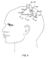
- the design requirements of the fixture can be understood by referring to Fig. 4 which shows how a fabricated fixture 400 will be attached to bone anchors 120 in the surgical phase.
- fixture 400 is attached to bone anchors 120 using bolts 432 which pass through openings 430 in fixture 400.
- mounting points of fixture 400 are located at the prior locations of the marker portions 126 of scanning markers 122.
- a planned actual trajectory 460 passes through an actual entry point 420 to an actual target point 410 corresponding to the planned entry image point 320 and target image point 310 (Fig. 3). Trajectory 460 passes through fixture 400 when attached to the skull.
- Fixture 400 includes a way of mounting an instrument guide onto it to guide a surgical instrument along trajectory 460.
- fixture 400 includes a mounting base 450 for attaching an instrument guide.
- Mounting base 450 has a flat surface with a central opening.
- trajectory 460 passes through the central opening of the mounting base and the flat surface of mounting base 450 is perpendicular to trajectory 460.
- the distance between target point 410 and the mounting base is also determined before the surgical phase, for example by designing the fixture so that this distance is a standard distance related to the type of instrument that will be used.
- fixture 400 for a particular patient and surgical procedure must satisfy several constraints including one or more of the following:
- an second exemplary fixture 500 is shown attached to the patient's head (Fig. 5a) and shown in a view along the planned trajectory (Fig. 5b) and in cross section (Fig. 5c).
- Fixture 500 is designed to attach to four bone anchors.
- Fixture 500 has a central mounting base 550 in a center section 520.
- Four "legs" 510 extend from the center section to four mounting pads 530 with mounting holes 540 through which fixture 500 is attached to the bone anchors.
- mounting base 550 is centered on planed trajectory 460.
- the distance between target point 410 and the center point 562 of the mounting base is set to a predetermined fixed distance.
- mounting pads 530 are designed as planar sections to lie over the mounting points and to be perpendicular to the axes of the bone anchors.
- Legs 510 are then designed as planar sections that join mounting pads 530 and center section 520.
- Fig. 5c the surface of the skull 534 is illustrated along with entry point 420.
- the mounting pads, legs, and center section are design to lie above and provide sufficient clearance above the skull.
- this approach to designing fixture 500 relies on knowledge of the orientations as well as the locations of the bone anchors.
- a single marking portion 126 is attached in scanning marker 122 to each bone anchor 120. Therefore only the location of each bone anchor is determined by locating the marker images of the scanning markers.
- alternative scanning markers 122 can be used.
- the alternative scanning markers have two marking portions 126 separated along the axis of the scanning marker. Locating the images of both the marking portions determines the orientation of the bone anchor.
- a second alternative is to use a normal direction to a surface models of the skull. The surface model of the skull can be computed directly from the scanned image using well known image processing techniques.
- a third alternative is to approximate the orientation of the bone anchors by fitting a surface through the locations of the scanning markers, and optionally through the entry point.
- a fourth alternative is to not rely on the mounting pads being normal to the axes of the bone anchors, relying instead on a mounting approach that is less sensitive to the orientation or the anchors. For instance, a ball can be mounted on each bone anchor and the fixture can have corresponding sockets which mate with the balls.
- Fixture 500 shown in Figs. 5a-c is made up of essentially planar sections.
- Alternative algorithmic design approaches can be used to design curved structures.
- the shape of the fixture can be determined using a surface spline with the mounting points and the mounting base being points at which constraints on the coefficients of the splines are determined.
- a solid model is a computer representation of a volume enclosed by a surface surrounding the entire volume.
- Various types of computer representations of the volume can be used.
- a common format is an ".stl" file that is used by many computer aided design (CAD) systems.
- the .stl file includes a set of representations of surface patches that together define a complete surface that encloses the volume.
- the stl file for the designed fixture is then used as the specification for fabrication of the fixture.
- the solid model file is transferred to a rapid prototyping and tooling (RPT) machine.
- the file can be transferred on a physical medium, such as a magnetic disk, sent over a data network, or used directly on the computer on which is was computed.
- a variety of RTP techniques can be used to fabricate the fixture.
- a Fused Deposition Modeling (FDM) machine such model FMD2000 manufactured by Stratasys, Inc. of Eden Prairie Minnesota, is used to make the three dimensional fixture from the .stl file.
- the FDM machine essentially robotically lays down a long ribbon of extruded material thereby slowly building up the modeled fixture. As material is laid down, it fuses with the previously laid down material making a homogeneous solid. The process results in a highly accurate fixture, within 5 mil of the specification in the .st1 file.
- Various materials can be used for the fixture.
- medical grade ABS is used.
- the ABS material can be drilled and tapped to provide mounting points at which an instrument guide is attached.
- the completed fixture is returned to the surgeon.
- the patient returns, with the bone anchors still intact, for the surgical phase.
- the fixture is sterilized and then the surgeon attaches the sterilized fixture to the bone anchors in the patient's skull and begins the surgical phase.
- the surgical phase for brain surgery involves several steps, including opening a burr hole, and the inserting of an instrument in the burr hole.
- the burr hole can be drilled prior to attaching the fixture, or can be drilled using the fixture. In the latter case, a drill guide is attached to the mounting base and a drill is inserted through the drill guide to drill the burr hole at the planned entry point.
- fixture 400 is used to support an instrument guide 600.
- instrument guide 600 supports an insertion tube 620 through which an instrument 610, such as a recording electrode, is passed.
- the instrument is attached to a drive 630 on instrument guide 600 for manually or automatically driving the instrument to target point 410. Since the separation of target point 410 and mounting base 450 is specified when the fixture is designed, if the length of the surgical instrument is predetermined, then the instrument guide can be calibrated to precisely insert the instrument to the target point. For instance, if the instrument is known to have a standard length, the separation of the target point and the mounting base on the fixture can be designed such that when the instrument drive is in its fully inserted position, the instrument has reached the planned target point.
- FIG. 7 An adjustable instrument guide 700 is attached to mounting base 450.
- the instrument guide is adjustable allowing the actual trajectory of instrument 610 to fall within a cone with an apex at entry point 420.
- an adjustable guidance fixture such as one described in copending U.S. Patent Application 09/063,658 filed 21 April 1998 or Provisional Application 60/096,384 filed 12 August 1998 can be used. Both of these copending applications are incorporated herein by reference.
- adjustable instrument guide 700 is attached in a precise relationship to target point 410 and entry point 420, a "registration" step of the type typically carried out in stereotactic surgery, used to conformally map a physical coordinate system to an image coordinate system, is not needed.
- instrument guide 700 can include encoders that generate signals which encode the adjustment of the actual trajectory relative to the planned trajectory, allowing precise visual feedback to be computed and displayed to a surgeon.
- Instrument guide can also be actuated allowing remote or robotic control of the instrument and the guide.
- the fabricated fixture is attached to bone anchors.
- Alternative embodiments attach the fixture to the body in different ways.
- other types of inserts or bone anchors can be attached to the skull.
- the fixture can be designed to precisely clamp onto the patient's head.
- two mating halves 810, 820 of a fixture 800 match the contours of cheek bones and forehead, and the contours of the back of the head, respectively.
- the contours of the patients head are derived from the a model of the skull that is computed automatically from the scanned image.
- the design (i.e., the solid model) of the fixture is determined algorithmically from the locations and orientations of points, including the mounting points, the target point and the entry point.
- An alternative approach to design of the fixture involves interaction with the surgeon. Rather than having to specify a detailed design for the fixture, the surgeon has control over a limited number of deformations of a standard fixture.
- a set of "standard” fixtures are used as the basis of the procedure.
- Each of the standard fixtures is described using a "logical model" in which geometric relationships of various elements of the fixture are explicitly identified. Examples of constraints described in the logical model include the shape of the mounting base (which is not deformed), and the connections of sections such as the mounting legs and central section.
- the surgeon selects one of the standard fixtures.
- a computer aided graphic design (CAGD) tool the surgeon views both a representation of the body and a representation of the fixture.
- the standard fixture does not satisfy any of the design constraints.
- the surgeon adjusts the fixture design so that the fixture will mate with the bone anchor, and so that the mounting base will have the correct location and orientation with respect to the entry and target points.
- the surgeon can adjust other aspects of the design, for example, deforming the fixture to allow sufficient clearance for an ear.
- Another embodiment of the invention is directed to spinal surgery.
- a three-dimensional scanned image is taken of the patient, in this case of his or her spine.
- no anchor points or scanning markers are necessarily applied to the spine, however.
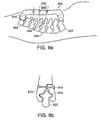
- the surgeon identifies target points 934 in the image of a spine 920, for example, points at which screws are to be inserted into the spine.
- the surgeon also plans trajectories 932 to reach the target points, for example determining the angles at which the screw holes will be drilled.
- a computer model of the segments of the spine 920 is formed from the scanned image.
- the surgeon identifies two segments 922 to which a customized fixture 900 is to be attached.
- the models of segments 922 are used to form clamp sections which mate with the contours of the segments.
- a portion 910 of the clamp section is formed in one piece with the main section of the fixture.
- a second portion 912 of each clamp section is formed as a separate component.
- the two portions of the clamp section are drawn together to attach the fixture to the spinal segments.
- Fixture 900 is formed to match the curvature of spine 920 as it is scanned. For instance, the separation of segments 922 matches the separation in the scanned image.
- each instrument guide 930 is formed in fixture 900.
- each instrument guide can be a elongated hole into which a drill is inserted.
- the instrument guides can be designed so that not only the orientation but also the depth of the holes drilled into the spinal segments are precisely determined by the instrument guides.
- Another embodiment directed to spinal surgery not only addresses operations to be performed on the spine in the configuration that it was scanned, but also address manipulating the spine to a desired curvature different from that in the scanned image.
- a modified spinal model is also derived.
- the modified model represents the desired curvature of the spine.
- a second fixture is designed according to the modified model. After the first fixture is removed, the second fixture is attached to achieve the desired curvature of the spine.
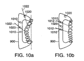
- FIG. 10a-b A related embodiment is illustrated schematically in Fig. 10a-b.
- This embodiment also uses the modified spinal model.
- additional guides 1010 are formed in the first fixture for the purpose of manipulating the spine into the desired configuration.
- additional guides 1010 are formed in the fixture corresponding to the orientations 1012 of the drilled holes after modification of the curvature, and screws inserted into the holes can be forced to lie in the desired orientations. Similar embodiments can be applied to correction and repair of orthopedic bone or joint deformity or fracture.
- Similar customized fixtures are also applicable to other types of surgical procedures in which a device must be precisely attached to a body.
- a precise instrument guide can be mounted with reference to facial features for eye surgery.
- one or more customized fixtures are used to support tracking markers that are used in sensor-tracked image-guided stereotactic surgery.
- bone anchors 120 are attached to a body.
- scanning markers are attached to the bone anchors, and the precise location of the bone anchors relative to the body are determined from a scanned image.
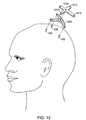
- a customized fixture 1200 is fabricated so that it has a known geometry relative to the mounting points which mate with bone anchors 120.
- a tracking fixture 1210 is attached to customized fixture 1200.
- Tracking fixture 1210 has a number of tracking markers 1215 attached to it. These markers are tracked during surgery.
- Tracking markers 1215 light-emitting diodes, or other emitters or reflectors of energy, whose three-dimensional location can be tracked using a remote sensing device, such as a camera array or a laser tracker.
- tracking fixture 1210 is shown rigidly mounted to the body through bone anchors 120.
- the locations of bone anchors relative to the body is determined from the scanned image.
- the geometry of customized fixture 1200 is determined in the fixture design phase.
- the location of tracking markers 1215 on tracking fixture 1210 are known from the predetermined geometry of the tracking fixture.
- the locations of tracking markers 1215 relative to bone anchors 120 are then computed from the geometry of the customized fixture and the geometry of the tracking fixture attached to it, in what is essentially a "computed registration" step.
- a surgical instrument 1310 for example a manually positioned probe, also includes multiple tracking markers 1315.
- a tracking system which includes a remote sensing device 1300, in this case a camera array, is used to track the three-dimensional locations of tracking markers 1215 and 1315.
- the tracking system is used to compute the relative position of the surgical instrument to the body.
- the tracking system displays a representation of surgical instrument 1310 on display system 1320 in a proper position and orientation relative to an image of the body.
- a manual registration phase of the type generally performed prior to conventional image-guided stereotactic surgery is not needed to determine the relative position of the instrument to the body.
- the computed registration step described above can be validated or double-checked using a manual procedure, for example, by touching the end of the surgical instrument to predetermined locations, such as the locations of the bone anchors, and verifying that the tracking system correctly calculates the locations.
- remote sensing device 1300 does not have to remain in a fixed location relative to the body, and in fact, both the body and sensing device 1300 can be freely moved around while continually tracking the location of the surgical instrument relative to the body.
- Tracking fixtures 1210 are rigidly attached to segments of an articulated portion of the body to track the relative positions of those segments.
- one tracking fixture 1210 is attached to a pelvis 1410 using a first customized fixture 1420, while a second tracking fixture 1210 is attached to a femur 1430 using a second customized fixture 1440.
- Customized fixtures 1420 and 1440 are designed and fabricated in the manner described above to mate with mounting anchors or screws on the pelvis and femur. For instance, anchoring screws 1442 are inserted into femur 1430. Scanning markers are attached to anchoring screws 1442 prior to scanning.
- Customized fixture 1440 is designed to have a known geometry and to mate with anchoring screws 1442.
- Customized fixture 1420 is similarly designed to mate with bone anchors that have been inserted into the pelvis.
- remote sensing device 1300 is used to determined the relative position and orientation of the two tracking fixtures 1210. Based on the computed registration of each tracking fixture to the rigid part of the body to which it is attached, the tracking system computes the relative position and orientation of femur 1430 and pelvis 1410 and displays representations of the femur and the pelvis on a display system 1450 in their proper geometric relationship.
- Similar customized fixtures are used to attach tracking fixtures to other parts of the body, for example to mulitple segments of the spine.
- Multiple tracking fixtures can also be used to track the configuration of skeletal joints during surgery or during other medical procedures.
- tracking fixtures which have integrated tracking markers, are attached to customized fixtures.
- a customized fixture can be designed and fabricated to directly hold the tracking markers, thereby being a customized tracking fixture (or "tracking frame"), which has a predetermined geometric relationship between the mounting points of the fixture and the locations of the tracking markers.
- Scanner 210 produces scanned image 230 which is passed to computer 220.
- Computer 220 is used by the surgeon to identify target and entry points, and possibly other points such as marker image points.
- a display and input device 1110 provides an interface for the surgeon. For instance, multiple planar views of the scanned image are presented to the surgeon, and the surgeon selects points using a mouse.
- Program storage 1125 is coupled to computer 220 for holding software used to implement procedures executed by computer 220.
- a library of standard fixtures 1120 can optionally be attached to computer 220. These standard fixtures are deformed using interactive procedures implemented on computer 220.
- the product of the procedures executed on computer 220 is solid model 1130 which completely specifies the shape of the fixture.
- This model is passed to a fabrication computer 1140 which derives tooling instructions 1150 which are passed to the RPT machine 1160.
- the RPT machine fabricates the fixture according to the tooling instructions.
Landscapes
- Health & Medical Sciences (AREA)
- Surgery (AREA)
- Life Sciences & Earth Sciences (AREA)
- Engineering & Computer Science (AREA)
- General Health & Medical Sciences (AREA)
- Public Health (AREA)
- Veterinary Medicine (AREA)
- Biomedical Technology (AREA)
- Heart & Thoracic Surgery (AREA)
- Medical Informatics (AREA)
- Molecular Biology (AREA)
- Animal Behavior & Ethology (AREA)
- Nuclear Medicine, Radiotherapy & Molecular Imaging (AREA)
- Pathology (AREA)
- Oral & Maxillofacial Surgery (AREA)
- Robotics (AREA)
- Chemical & Material Sciences (AREA)
- Manufacturing & Machinery (AREA)
- Materials Engineering (AREA)
- Surgical Instruments (AREA)
- Materials For Medical Uses (AREA)
- Prostheses (AREA)
- Orthopedics, Nursing, And Contraception (AREA)
- Apparatus For Radiation Diagnosis (AREA)
Claims (28)
- Verfahren zur Ausbildung einer individuumspezifischen chirurgischen Fixierungseinrichtung (400) zum Befestigen an einem Körper und zum Bereitstellen eines Bezugsaufbaus zum Orten eines Ziels (310) in dem Körper und zum Verarbeiten eines dreidimensionalen abgetasteten Bildes des Körpers einschließlich der Bestimmung einer Position des Ziels (310) in dem Körper und der Positionen von Einsätzen (120), die an dem Körper befestigt sind, dadurch gekennzeichnet, dass aus dem abgetasteten Bild Daten bestimmt werden, die einen Aufbau der chirurgischen Fixierungseinrichtung (400) kennzeichnen, die den Bezugsaufbau zum Führen eines chirurgischen Instruments aufweist, so dass die Fixierungseinrichtung, wenn sie in Bezug auf die Einsätze (120) befestigt ist, den Bezugsaufbau in einer festgelegten Position und Ausrichtung bezüglich des Ziels (310) in dem Körper hält.
- Verfahren nach Anspruch 1, bei welchem die Einsätze (120) Knochenverankerungen aufweisen und die chirurgische Fixierungseinrichtung (400), wenn sie an den Knochenverankerungen befestigt ist, einen Bezugsaufbau in einer festgelegten Position oder Ausrichtung bezüglich des Ziels (310) in dem Körper bereitstellt.
- Verfahren nach einem der Ansprüche 1 und 2, bei welchem weiterhin in dem abgetasteten Bild eine Vielzahl von Anbringungspunkten (330) für die chirurgische Fixierungseinrichtung (400) identifiziert werden und bei welchem zur Bestimmung der Daten, die den Aufbau der chirurgischen Fixierungseinrichtung (400) kennzeichnen, die Bestimmung einer geometrischen Beziehung zwischen entsprechenden Anbringungspunkten an der Fixierungseinrichtung und an dem Bezugsaufbau gehören.
- Verfahren nach einem der Ansprüche 1 bis 3, bei welchem zu dem Verarbeiten des dreidimensionalen abgetasteten Bildes das Orten von Abtastmarkierungen (122) gehört, die an dem Körper in dem dreidimensionalen Bild befestigt sind.
- Verfahren nach Anspruch 4, bei welchem die Einsätze (120) Verankerungen aufweisen, die zur Befestigung der chirurgischen Fixierungseinrichtung (400) an dem Körper geeignet sind und bei welchem zu dem Orten der Abtastmarkierungen (122) das Orten von Abtastmarkierungen gehört, die an den Verankerungen (120) befestigt sind.
- Verfahren nach einem der Ansprüche 1 bis 5, bei welchem weiterhin das Ziel (310) in dem abgetasteten Bild identifiziert wird.
- Verfahren nach Anspruch 6, bei welchem weiterhin eine Bahn (460) zum Erreichen des Ziels (310) identifiziert und die Position und Ausrichtung des Bezugsaufbaus bezüglich der identifizierten Bahn bestimmt wird.
- Verfahren nach einem der Ansprüche 1 bis 7, bei welchem zu dem Bestimmen der Daten, die den Aufbau der Fixierungseinrichtung kennzeichnen, das Bestimmen eines massiven Modells der Fixierungseinrichtung gehört, das das Volumen definiert, das von der Oberfläche der Fixierungseinrichtung eingeschlossen ist.
- Verfahren nach einem der Ansprüche 1 bis 8, bei welchem der Bezugsaufbau so konfiguriert wird, dass ein Bezugsaufbau zum Führen eines Instruments zu dem Ziel (310) bereitgestellt wird.
- Verfahren nach einem der Ansprüche 1 bis 9, bei welchem der Bezugsaufbau so konfiguriert wird, dass eine Vielzahl von Aufspürmarkierungen (1215) an der chirurgischen Fixierungseinrichtung (400) befestigt sind.
- Verfahren nach Anspruch 10, bei welchem Einpassdaten berechnet werden, die auf den konfigurierten Positionen der Aufspürmarkierungen (1215) in der chirurgischen Fixierungseinrichtung (400) basieren.
- Verfahren nach Anspruch 11, bei welchem weiterhin die berechneten Einpassdaten zur Anzeige einer Darstellung einer Aufspürvorrichtung in Verbindung mit einem graphischen Bild des Körpers verwendet werden.
- Verfahren nach einem der Ansprüche 1 bis 12, bei welchem der Körper mehrere Anbringpositionen (430) aufweist und der bestimmte Aufbau der chirurgischen Fixierungseinrichtung (400) so beschaffen ist, dass, wenn der Körper in Beziehung zu den Einsätzen (120) festgelegt ist, er mit den Anbringungspositionen in einer vorgegebenen geometrischen Beziehung gehalten wird.
- Verfahren nach einem der Ansprüche 1 bis 13, bei welchem der Körper eine Wirbelsäule und die Anbringposition ein Spinalsegment aufweist und bei dem Verfahren weiterhin ein Modell der Wirbelsäule gebildet wird.
- Verfahren nach Anspruch 14, bei welchem weiterhin ein korrigiertes Modell der Wirbelsäule in einer korrigierten Konfiguration ausgebildet wird und der bestimmte Aufbau der chirurgischen Fixierungseinrichtung (400) so beschaffen ist, dass sie, wenn sie befestigt ist, einen zweiten Bezugsaufbau an einer bestimmten Position und Ausrichtung bezüglich des Ziels (310) in der korrigierten Konfiguration der Wirbelsäule bereitstellt.
- Verfahren nach einem der Ansprüche 1 bis 15, bei welchem zu dem Bestimmen der Daten, die den Aufbau der chirurgischen Fixierungseinrichtung (400) charakterisieren, das Auswählen eines Modells einer Standardfixierungseinrichtung und das Umformen des Modells der Standardfixierungseinrichtung gehören, um das Standardmodell an das Ziel (310) und die Anbringposition anzupassen.
- Verfahren nach einem der Ansprüche 1 bis 16, bei welchem der Aufbau der chirurgischen Fixierungseinrichtung (400) einen Abschnitt (450) zum Befestigen eines chirurgischen Instruments aufweist, so dass, wenn im Einsatz die Fixierungseinrichtung (400) an der Anbringposition (330) an dem Körper befestigt ist, der Abschnitt (450) zum Befestigen des chirurgischen Instruments sich in einer vorgegebenen geometrischen Beziehung bezüglich des Ziels (310) befindet.
- Verfahren nach Anspruch 19, bei welchem zu dem Bestimmen der Daten, die den Aufbau der Fixierungseinrichtung (400) charakterisieren, das Bestimmen einer Position und einer Ausrichtung für den Abschnitt (450) zum Befestigen des chirurgischen Instruments bezüglich der Anbringstelle (330) gehört, wobei die Position des Ziels (310) und die Anbringposition (330) verwendet werden.
- Verfahren nach Anspruch 18, bei welchem zu dem Bestimmen der Position und der Ausrichtung für die Instrumentenführung das Bestimmen einer Bahn (460) durch den Körper, die durch das Ziel (310) geht, das Bestimmen der Ausrichtung für den Abschnitt (450) zum Befestigen des Instruments basierend auf der Bahn (460) sowie das Bestimmen der Position für den Abschnitt (450) zum Befestigen des Instruments basierend auf einer Distanz längs der Bahn (460) vom Ziel (310) aus gehören.
- Verfahren nach einem der Ansprüche 17 bis 19, bei welchem der Abschnitt zum Befestigen des chirurgischen Instruments eine Haltebasis (450) zum Befestigen einer entfernbaren Instrumentenführung an der chirurgischen Fixierungseinrichtung (400) aufweist.
- Verfahren nach Anspruch 20, bei welchem die Haltebasis (450) einen planaren Bereich und der Abschnitt zum Befestigen des chirurgischen Instruments eine Öffnung durch die Fixierungseinrichtung an der Haltebasis aufweist.
- Verfahren nach Anspruch 21, bei welchem der planare Bereich der Haltebasis (450) sich in einer Ebene befindet, die senkrecht zu einer Bahn (460) von der Haltebasis aus zum Ziel (310) ist, wenn die Fixierungseinrichtung (400) an der Anbringposition (330) an dem Körper befestigt ist.
- Verfahren nach einem der Ansprüche 1 bis 22, bei welchem weiterhin die individuumspezifische Fixierungseinrichtung (400) entsprechend den bestimmten Daten hergestellt wird, die den Aufbau der individuumspezifischen Fixierungseinrichtung kennzeichnen.
- Verfahren nach Anspruch 23, bei welchem zu der Herstellung der individuumspezifischen Fixierungseinrichtung (400) die Ausbildung eines unitären Aufbaus unter Verwendung eines rechnergesteuerten Prozesses gehört.
- Verfahren nach Anspruch 23 und 24, bei welchem zu der Herstellung der individuumspezifischen Fixierungseinrichtung (400) die Verwendung einer schnellen Prototypbildungs- und Bearbeitungstechnik (RPT) gehört.
- Rechnerprogramm mit einem Code, der so ausgelegt ist, dass er alle Verfahrensschritte nach einem der Ansprüche 1 bis 22 vornimmt, wenn das Programm auf einem Datenverarbeitungssystem ausgeführt wird.
- Rechnerprogramm nach Anspruch 26 verwirklicht auf einem rechnerlesbaren Medium.
- Rechnerimplementiertes System mit einem Rechenprogramm nach Anspruch 26.
Applications Claiming Priority (3)
| Application Number | Priority Date | Filing Date | Title |
|---|---|---|---|
| US110070 | 1998-07-06 | ||
| US09/110,070 US6327491B1 (en) | 1998-07-06 | 1998-07-06 | Customized surgical fixture |
| PCT/US1999/015006 WO2000001316A1 (en) | 1998-07-06 | 1999-07-02 | Customized surgical fixture |
Publications (2)
| Publication Number | Publication Date |
|---|---|
| EP1094760A1 EP1094760A1 (de) | 2001-05-02 |
| EP1094760B1 true EP1094760B1 (de) | 2006-03-29 |
Family
ID=22331074
Family Applications (1)
| Application Number | Title | Priority Date | Filing Date |
|---|---|---|---|
| EP99935401A Expired - Lifetime EP1094760B1 (de) | 1998-07-06 | 1999-07-02 | Verfahren zur herstellung einer individuell erzeugten chirurgischen halterung |
Country Status (6)
| Country | Link |
|---|---|
| US (3) | US6327491B1 (de) |
| EP (1) | EP1094760B1 (de) |
| AT (1) | ATE321499T1 (de) |
| AU (1) | AU5088599A (de) |
| DE (1) | DE69930638T2 (de) |
| WO (1) | WO2000001316A1 (de) |
Cited By (2)
| Publication number | Priority date | Publication date | Assignee | Title |
|---|---|---|---|---|
| WO2016071915A1 (en) * | 2014-11-09 | 2016-05-12 | Sensomedical Labs Ltd. | Custom three dimensional forming of surgical guides |
| US12029896B2 (en) | 2016-05-11 | 2024-07-09 | Senso Medical Labs Ltd. | Thread bidirectional interlocking of electrode lead |
Families Citing this family (281)
| Publication number | Priority date | Publication date | Assignee | Title |
|---|---|---|---|---|
| US6459927B1 (en) * | 1999-07-06 | 2002-10-01 | Neutar, Llc | Customizable fixture for patient positioning |
| US6327491B1 (en) * | 1998-07-06 | 2001-12-04 | Neutar, Llc | Customized surgical fixture |
| US6491699B1 (en) | 1999-04-20 | 2002-12-10 | Surgical Navigation Technologies, Inc. | Instrument guidance method and system for image guided surgery |
| US20020168618A1 (en) * | 2001-03-06 | 2002-11-14 | Johns Hopkins University School Of Medicine | Simulation system for image-guided medical procedures |
| WO2001010339A2 (en) | 1999-08-11 | 2001-02-15 | Case Western Reserve University | Method and apparatus for producing an implant |
| US9208558B2 (en) | 1999-08-11 | 2015-12-08 | Osteoplastics Llc | Methods and systems for producing an implant |
| US8781557B2 (en) * | 1999-08-11 | 2014-07-15 | Osteoplastics, Llc | Producing a three dimensional model of an implant |
| EP1227768B1 (de) * | 1999-10-29 | 2006-10-04 | Neutar, LLC | Verfahren zum entwurf von anpassbarer fixiervorrichtung zur patientenpositionierung |
| EP1226553A2 (de) * | 1999-11-03 | 2002-07-31 | Case Western Reserve University | System und verfahren zur erzeugung eines drei-dimensionalen models |
| NO313573B1 (no) * | 2000-01-06 | 2002-10-28 | Medinnova Sf | Verktöy for bruk ved hjerneoperasjoner, samt system for å bestemme innföringsdybden til en sonde eller lignende vedhjerneoperasjoner og koordinatene til verktöyet og sonden vedhjerneoperasjoner |
| US6725080B2 (en) * | 2000-03-01 | 2004-04-20 | Surgical Navigation Technologies, Inc. | Multiple cannula image guided tool for image guided procedures |
| US6712856B1 (en) * | 2000-03-17 | 2004-03-30 | Kinamed, Inc. | Custom replacement device for resurfacing a femur and method of making the same |
| US7660621B2 (en) | 2000-04-07 | 2010-02-09 | Medtronic, Inc. | Medical device introducer |
| US7366561B2 (en) | 2000-04-07 | 2008-04-29 | Medtronic, Inc. | Robotic trajectory guide |
| AU2001285071A1 (en) | 2000-08-17 | 2002-02-25 | John David | Trajectory guide with instrument immobilizer |
| JP4726032B2 (ja) * | 2000-08-31 | 2011-07-20 | スミス アンド ネフュー オーソペディックス アーゲー | 体肢の力学軸の位置を検出する方法及び装置 |
| DE20120221U1 (de) * | 2001-12-13 | 2002-04-18 | TRW Automotive Safety Systems GmbH & Co. KG, 63743 Aschaffenburg | Lenkvorrichtung für ein Kraftfahrzeug |
| US9155544B2 (en) | 2002-03-20 | 2015-10-13 | P Tech, Llc | Robotic systems and methods |
| US6942667B1 (en) * | 2002-04-02 | 2005-09-13 | Vanderbilt University | Bone anchor |
| US6993374B2 (en) * | 2002-04-17 | 2006-01-31 | Ricardo Sasso | Instrumentation and method for mounting a surgical navigation reference device to a patient |
| US6980849B2 (en) * | 2002-04-17 | 2005-12-27 | Ricardo Sasso | Instrumentation and method for performing image-guided spinal surgery using an anterior surgical approach |
| US8180429B2 (en) * | 2002-04-17 | 2012-05-15 | Warsaw Orthopedic, Inc. | Instrumentation and method for mounting a surgical navigation reference device to a patient |
| US20030205538A1 (en) | 2002-05-03 | 2003-11-06 | Randel Dorian | Methods and apparatus for isolating platelets from blood |
| US7992725B2 (en) | 2002-05-03 | 2011-08-09 | Biomet Biologics, Llc | Buoy suspension fractionation system |
| US7832566B2 (en) | 2002-05-24 | 2010-11-16 | Biomet Biologics, Llc | Method and apparatus for separating and concentrating a component from a multi-component material including macroparticles |
| US8801720B2 (en) * | 2002-05-15 | 2014-08-12 | Otismed Corporation | Total joint arthroplasty system |
| DE10306793A1 (de) * | 2002-05-21 | 2003-12-04 | Plus Endoprothetik Ag Rotkreuz | Anordnung und Verfahren zur intraoperativen Festlegung der Lage eines Gelenkersatzimplantats |
| US20060278588A1 (en) | 2002-05-24 | 2006-12-14 | Woodell-May Jennifer E | Apparatus and method for separating and concentrating fluids containing multiple components |
| US7845499B2 (en) | 2002-05-24 | 2010-12-07 | Biomet Biologics, Llc | Apparatus and method for separating and concentrating fluids containing multiple components |
| WO2003099412A1 (en) | 2002-05-24 | 2003-12-04 | Biomet Manufacturing Corp. | Apparatus and method for separating and concentrating fluids containing multiple components |
| US7720522B2 (en) | 2003-02-25 | 2010-05-18 | Medtronic, Inc. | Fiducial marker devices, tools, and methods |
| US20040019265A1 (en) * | 2002-07-29 | 2004-01-29 | Mazzocchi Rudy A. | Fiducial marker devices, tools, and methods |
| US20040030237A1 (en) * | 2002-07-29 | 2004-02-12 | Lee David M. | Fiducial marker devices and methods |
| US7787934B2 (en) | 2002-07-29 | 2010-08-31 | Medtronic, Inc. | Fiducial marker devices, tools, and methods |
| US7704260B2 (en) | 2002-09-17 | 2010-04-27 | Medtronic, Inc. | Low profile instrument immobilizer |
| US7636596B2 (en) | 2002-12-20 | 2009-12-22 | Medtronic, Inc. | Organ access device and method |
| US7896889B2 (en) | 2003-02-20 | 2011-03-01 | Medtronic, Inc. | Trajectory guide with angled or patterned lumens or height adjustment |
| US7559935B2 (en) | 2003-02-20 | 2009-07-14 | Medtronic, Inc. | Target depth locators for trajectory guide for introducing an instrument |
| US7129360B2 (en) * | 2003-04-07 | 2006-10-31 | Fmc Corporation | Using alkylmetal reagents for directed metalation of azaaromatics |
| US7662157B2 (en) * | 2003-08-21 | 2010-02-16 | Osteomed L.P. | Bone anchor system |
| US6944518B2 (en) * | 2003-09-18 | 2005-09-13 | Depuy Products, Inc. | Customized prosthesis and method of designing and manufacturing a customized prosthesis by utilizing computed tomography data |
| DE10343826B4 (de) * | 2003-09-22 | 2006-02-09 | Plus-Endoprothetik Ag | Knochenfester Lokator und Navigationssystem |
| US7651506B2 (en) * | 2003-10-02 | 2010-01-26 | University Of Florida Research Foundation, Inc. | Frameless stereotactic guidance of medical procedures |
| US20050075649A1 (en) * | 2003-10-02 | 2005-04-07 | Bova Frank Joseph | Frameless stereotactic guidance of medical procedures |
| US7862570B2 (en) | 2003-10-03 | 2011-01-04 | Smith & Nephew, Inc. | Surgical positioners |
| US8175683B2 (en) * | 2003-12-30 | 2012-05-08 | Depuy Products, Inc. | System and method of designing and manufacturing customized instrumentation for accurate implantation of prosthesis by utilizing computed tomography data |
| EP1722848A1 (de) | 2004-02-13 | 2006-11-22 | Medtronic, Inc. | Verfahren und gerät zur befestigung einer therapeutischen vorrichtung in einem bohrloch |
| US7497863B2 (en) | 2004-12-04 | 2009-03-03 | Medtronic, Inc. | Instrument guiding stage apparatus and method for using same |
| US7744606B2 (en) | 2004-12-04 | 2010-06-29 | Medtronic, Inc. | Multi-lumen instrument guide |
| WO2007003019A2 (en) * | 2005-07-01 | 2007-01-11 | K.U. Leuven Research & Development | Means for functional restoration of a damaged nervous system |
| US7983777B2 (en) * | 2005-08-19 | 2011-07-19 | Mark Melton | System for biomedical implant creation and procurement |
| EP1779788B1 (de) * | 2005-10-28 | 2008-05-07 | BrainLAB AG | Unterdruck-Haltevorrichtung |
| US8506597B2 (en) * | 2011-10-25 | 2013-08-13 | Biomet Sports Medicine, Llc | Method and apparatus for interosseous membrane reconstruction |
| US9808262B2 (en) | 2006-02-15 | 2017-11-07 | Howmedica Osteonics Corporation | Arthroplasty devices and related methods |
| CA2642615A1 (en) | 2006-02-15 | 2007-08-30 | Otismed Corp | Arthroplasty jigs and related methods |
| US9011441B2 (en) * | 2006-02-17 | 2015-04-21 | Paradigm Spine, L.L.C. | Method and system for performing interspinous space preparation for receiving an implant |
| US8282646B2 (en) | 2006-02-27 | 2012-10-09 | Biomet Manufacturing Corp. | Patient specific knee alignment guide and associated method |
| US9907659B2 (en) | 2007-04-17 | 2018-03-06 | Biomet Manufacturing, Llc | Method and apparatus for manufacturing an implant |
| US8608749B2 (en) | 2006-02-27 | 2013-12-17 | Biomet Manufacturing, Llc | Patient-specific acetabular guides and associated instruments |
| US8603180B2 (en) | 2006-02-27 | 2013-12-10 | Biomet Manufacturing, Llc | Patient-specific acetabular alignment guides |
| US8133234B2 (en) | 2006-02-27 | 2012-03-13 | Biomet Manufacturing Corp. | Patient specific acetabular guide and method |
| US8535387B2 (en) | 2006-02-27 | 2013-09-17 | Biomet Manufacturing, Llc | Patient-specific tools and implants |
| US7967868B2 (en) | 2007-04-17 | 2011-06-28 | Biomet Manufacturing Corp. | Patient-modified implant and associated method |
| US9345548B2 (en) | 2006-02-27 | 2016-05-24 | Biomet Manufacturing, Llc | Patient-specific pre-operative planning |
| US8591516B2 (en) | 2006-02-27 | 2013-11-26 | Biomet Manufacturing, Llc | Patient-specific orthopedic instruments |
| US8473305B2 (en) | 2007-04-17 | 2013-06-25 | Biomet Manufacturing Corp. | Method and apparatus for manufacturing an implant |
| US8608748B2 (en) | 2006-02-27 | 2013-12-17 | Biomet Manufacturing, Llc | Patient specific guides |
| US9289253B2 (en) | 2006-02-27 | 2016-03-22 | Biomet Manufacturing, Llc | Patient-specific shoulder guide |
| US9918740B2 (en) | 2006-02-27 | 2018-03-20 | Biomet Manufacturing, Llc | Backup surgical instrument system and method |
| US9113971B2 (en) | 2006-02-27 | 2015-08-25 | Biomet Manufacturing, Llc | Femoral acetabular impingement guide |
| US10278711B2 (en) | 2006-02-27 | 2019-05-07 | Biomet Manufacturing, Llc | Patient-specific femoral guide |
| US8298237B2 (en) * | 2006-06-09 | 2012-10-30 | Biomet Manufacturing Corp. | Patient-specific alignment guide for multiple incisions |
| US8092465B2 (en) | 2006-06-09 | 2012-01-10 | Biomet Manufacturing Corp. | Patient specific knee alignment guide and associated method |
| US8407067B2 (en) | 2007-04-17 | 2013-03-26 | Biomet Manufacturing Corp. | Method and apparatus for manufacturing an implant |
| US8377066B2 (en) | 2006-02-27 | 2013-02-19 | Biomet Manufacturing Corp. | Patient-specific elbow guides and associated methods |
| US8070752B2 (en) | 2006-02-27 | 2011-12-06 | Biomet Manufacturing Corp. | Patient specific alignment guide and inter-operative adjustment |
| US9339278B2 (en) | 2006-02-27 | 2016-05-17 | Biomet Manufacturing, Llc | Patient-specific acetabular guides and associated instruments |
| US8241293B2 (en) | 2006-02-27 | 2012-08-14 | Biomet Manufacturing Corp. | Patient specific high tibia osteotomy |
| US8864769B2 (en) | 2006-02-27 | 2014-10-21 | Biomet Manufacturing, Llc | Alignment guides with patient-specific anchoring elements |
| US8858561B2 (en) | 2006-06-09 | 2014-10-14 | Blomet Manufacturing, LLC | Patient-specific alignment guide |
| US20150335438A1 (en) | 2006-02-27 | 2015-11-26 | Biomet Manufacturing, Llc. | Patient-specific augments |
| US8568487B2 (en) | 2006-02-27 | 2013-10-29 | Biomet Manufacturing, Llc | Patient-specific hip joint devices |
| US9173661B2 (en) | 2006-02-27 | 2015-11-03 | Biomet Manufacturing, Llc | Patient specific alignment guide with cutting surface and laser indicator |
| US8567609B2 (en) | 2006-05-25 | 2013-10-29 | Biomet Biologics, Llc | Apparatus and method for separating and concentrating fluids containing multiple components |
| US9795399B2 (en) | 2006-06-09 | 2017-10-24 | Biomet Manufacturing, Llc | Patient-specific knee alignment guide and associated method |
| US8560047B2 (en) | 2006-06-16 | 2013-10-15 | Board Of Regents Of The University Of Nebraska | Method and apparatus for computer aided surgery |
| WO2008014261A2 (en) * | 2006-07-24 | 2008-01-31 | Vanderbilt University | Adjustable surgical platform and surgical instrument using same |
| US8771290B2 (en) * | 2006-07-24 | 2014-07-08 | Vanderbilt University | Microstereotactic table |
| GB2442441B (en) | 2006-10-03 | 2011-11-09 | Biomet Uk Ltd | Surgical instrument |
| GB2445961B (en) * | 2006-10-31 | 2009-02-04 | Prosurgics Ltd | Fiducial marker placement |
| US20080119847A1 (en) * | 2006-11-16 | 2008-05-22 | Zimmer Technology, Inc. | Bone peg for use in a bone fixation system |
| US8460302B2 (en) | 2006-12-18 | 2013-06-11 | Otismed Corporation | Arthroplasty devices and related methods |
| DE202006019649U1 (de) * | 2006-12-22 | 2007-08-16 | Brainlab Ag | Navigierte Applikationsführung für gezielte Spinalarzneimittelzufuhr |
| US20080171930A1 (en) * | 2007-01-16 | 2008-07-17 | Ar2 Partners, Inc. | Method and apparatus for positioning an instrument in a predetermined region within a patient's body |
| US8374679B2 (en) * | 2007-02-22 | 2013-02-12 | Vanderbilt University | System and methods for determining the orientation and position of a bone-implanted anchor |
| WO2008109751A1 (en) * | 2007-03-06 | 2008-09-12 | The Cleveland Clinic Foundation | Method and apparatus for preparing for a surgical procedure |
| JP5479319B2 (ja) | 2007-04-12 | 2014-04-23 | バイオメット・バイオロジックス・リミテッド・ライアビリティ・カンパニー | ブイ式懸濁液分画システム |
| US8328024B2 (en) | 2007-04-12 | 2012-12-11 | Hanuman, Llc | Buoy suspension fractionation system |
| AU2008250951B2 (en) * | 2007-05-14 | 2014-06-05 | Queen's University At Kingston | Patient-specific surgical guidance tool and method of use |
| US9351744B2 (en) | 2007-05-14 | 2016-05-31 | Queen's University At Kingston | Patient-specific surgical guidance tool and method of use |
| CN101396291B (zh) * | 2007-09-24 | 2010-12-08 | 上海交通大学医学院附属第九人民医院 | 一种个性化下颌角肥大手术导航实体的制造方法 |
| US8265949B2 (en) | 2007-09-27 | 2012-09-11 | Depuy Products, Inc. | Customized patient surgical plan |
| US9786022B2 (en) | 2007-09-30 | 2017-10-10 | DePuy Synthes Products, Inc. | Customized patient-specific bone cutting blocks |
| US8357111B2 (en) | 2007-09-30 | 2013-01-22 | Depuy Products, Inc. | Method and system for designing patient-specific orthopaedic surgical instruments |
| US8398645B2 (en) * | 2007-09-30 | 2013-03-19 | DePuy Synthes Products, LLC | Femoral tibial customized patient-specific orthopaedic surgical instrumentation |
| US9173662B2 (en) | 2007-09-30 | 2015-11-03 | DePuy Synthes Products, Inc. | Customized patient-specific tibial cutting blocks |
| WO2011106399A1 (en) | 2010-02-25 | 2011-09-01 | Depuy Products, Inc. | Customized patient-specific bone cutting blocks |
| USD642263S1 (en) | 2007-10-25 | 2011-07-26 | Otismed Corporation | Arthroplasty jig blank |
| US8460303B2 (en) | 2007-10-25 | 2013-06-11 | Otismed Corporation | Arthroplasty systems and devices, and related methods |
| US10582934B2 (en) | 2007-11-27 | 2020-03-10 | Howmedica Osteonics Corporation | Generating MRI images usable for the creation of 3D bone models employed to make customized arthroplasty jigs |
| AU2008335328B2 (en) | 2007-12-06 | 2014-11-27 | Smith & Nephew, Inc. | Systems and methods for determining the mechanical axis of a femur |
| US8160345B2 (en) | 2008-04-30 | 2012-04-17 | Otismed Corporation | System and method for image segmentation in generating computer models of a joint to undergo arthroplasty |
| US8545509B2 (en) | 2007-12-18 | 2013-10-01 | Otismed Corporation | Arthroplasty system and related methods |
| US8777875B2 (en) | 2008-07-23 | 2014-07-15 | Otismed Corporation | System and method for manufacturing arthroplasty jigs having improved mating accuracy |
| US8311306B2 (en) | 2008-04-30 | 2012-11-13 | Otismed Corporation | System and method for image segmentation in generating computer models of a joint to undergo arthroplasty |
| US8715291B2 (en) | 2007-12-18 | 2014-05-06 | Otismed Corporation | Arthroplasty system and related methods |
| US8617171B2 (en) | 2007-12-18 | 2013-12-31 | Otismed Corporation | Preoperatively planning an arthroplasty procedure and generating a corresponding patient specific arthroplasty resection guide |
| US8221430B2 (en) * | 2007-12-18 | 2012-07-17 | Otismed Corporation | System and method for manufacturing arthroplasty jigs |
| US8737700B2 (en) | 2007-12-18 | 2014-05-27 | Otismed Corporation | Preoperatively planning an arthroplasty procedure and generating a corresponding patient specific arthroplasty resection guide |
| US8480679B2 (en) | 2008-04-29 | 2013-07-09 | Otismed Corporation | Generation of a computerized bone model representative of a pre-degenerated state and useable in the design and manufacture of arthroplasty devices |
| EP2567692B1 (de) | 2008-02-27 | 2016-04-06 | Biomet Biologics, LLC | Verwendung einer Vorrichtung zur Erzeugung Interleukin-1-rezeptorantagonistreicher Lösungen |
| US20090222059A1 (en) * | 2008-02-28 | 2009-09-03 | Searete Llc, A Limited Liability Corporation Of The State Of Delaware | Shaped implantation device |
| US20090221898A1 (en) * | 2008-02-28 | 2009-09-03 | Hillis W Daniel | Shaped surgical tool |
| US8734455B2 (en) | 2008-02-29 | 2014-05-27 | Otismed Corporation | Hip resurfacing surgical guide tool |
| WO2009111338A1 (en) | 2008-02-29 | 2009-09-11 | Biomet Manufacturing Corp. | A system and process for separating a material |
| US8549888B2 (en) | 2008-04-04 | 2013-10-08 | Nuvasive, Inc. | System and device for designing and forming a surgical implant |
| US8617175B2 (en) | 2008-12-16 | 2013-12-31 | Otismed Corporation | Unicompartmental customized arthroplasty cutting jigs and methods of making the same |
| US8992538B2 (en) | 2008-09-30 | 2015-03-31 | DePuy Synthes Products, Inc. | Customized patient-specific acetabular orthopaedic surgical instrument and method of use and fabrication |
| US8170641B2 (en) | 2009-02-20 | 2012-05-01 | Biomet Manufacturing Corp. | Method of imaging an extremity of a patient |
| US12383287B2 (en) | 2009-02-24 | 2025-08-12 | Microport Orthopedics Holdings, Inc. | Systems and methods for installing an orthopedic implant |
| US8808303B2 (en) | 2009-02-24 | 2014-08-19 | Microport Orthopedics Holdings Inc. | Orthopedic surgical guide |
| US9017334B2 (en) | 2009-02-24 | 2015-04-28 | Microport Orthopedics Holdings Inc. | Patient specific surgical guide locator and mount |
| US8808297B2 (en) | 2009-02-24 | 2014-08-19 | Microport Orthopedics Holdings Inc. | Orthopedic surgical guide |
| US8187475B2 (en) | 2009-03-06 | 2012-05-29 | Biomet Biologics, Llc | Method and apparatus for producing autologous thrombin |
| US8551023B2 (en) | 2009-03-31 | 2013-10-08 | Depuy (Ireland) | Device and method for determining force of a knee joint |
| US8721568B2 (en) | 2009-03-31 | 2014-05-13 | Depuy (Ireland) | Method for performing an orthopaedic surgical procedure |
| US8313954B2 (en) | 2009-04-03 | 2012-11-20 | Biomet Biologics, Llc | All-in-one means of separating blood components |
| US8794977B2 (en) * | 2009-04-29 | 2014-08-05 | Lifemodeler, Inc. | Implant training system |
| US9011800B2 (en) | 2009-07-16 | 2015-04-21 | Biomet Biologics, Llc | Method and apparatus for separating biological materials |
| DE102009028503B4 (de) | 2009-08-13 | 2013-11-14 | Biomet Manufacturing Corp. | Resektionsschablone zur Resektion von Knochen, Verfahren zur Herstellung einer solchen Resektionsschablone und Operationsset zur Durchführung von Kniegelenk-Operationen |
| WO2011060536A1 (en) | 2009-11-17 | 2011-05-26 | Queen's University At Kingston | Patient-specific guide for acetabular cup placement |
| EP2538855A4 (de) | 2010-02-25 | 2016-08-03 | Depuy Products Inc | Angepasste patientenspezifische schienbeinschneideblöcke |
| US10149722B2 (en) | 2010-02-25 | 2018-12-11 | DePuy Synthes Products, Inc. | Method of fabricating customized patient-specific bone cutting blocks |
| US8632547B2 (en) | 2010-02-26 | 2014-01-21 | Biomet Sports Medicine, Llc | Patient-specific osteotomy devices and methods |
| US9066727B2 (en) | 2010-03-04 | 2015-06-30 | Materialise Nv | Patient-specific computed tomography guides |
| US9579106B2 (en) | 2010-03-31 | 2017-02-28 | New York Society For The Relief Of The Ruptured And Crippled, Maintaining The Hospital For Special Surgery | Shoulder arthroplasty instrumentation |
| US8591391B2 (en) | 2010-04-12 | 2013-11-26 | Biomet Biologics, Llc | Method and apparatus for separating a material |
| WO2011156755A2 (en) | 2010-06-11 | 2011-12-15 | Smith & Nephew, Inc. | Patient-matched instruments |
| CN103140185A (zh) * | 2010-07-23 | 2013-06-05 | 洛桑联邦理工学院 | 用于神经外科装置的可调节固定系统 |
| US8808302B2 (en) | 2010-08-12 | 2014-08-19 | DePuy Synthes Products, LLC | Customized patient-specific acetabular orthopaedic surgical instrument and method of use and fabrication |
| WO2012024281A2 (en) * | 2010-08-16 | 2012-02-23 | Smith & Nephew, Inc. | Patient-matched tissue guide for placing a surgical device |
| CN103379924B (zh) | 2010-08-20 | 2015-07-29 | 凯斯西储大学 | 植入物的连续数字光处理添加制造 |
| US11865785B2 (en) | 2010-08-20 | 2024-01-09 | H. David Dean | Continuous digital light processing additive manufacturing of implants |
| US9271744B2 (en) | 2010-09-29 | 2016-03-01 | Biomet Manufacturing, Llc | Patient-specific guide for partial acetabular socket replacement |
| US9717508B2 (en) * | 2010-10-29 | 2017-08-01 | The Cleveland Clinic Foundation | System of preoperative planning and provision of patient-specific surgical aids |
| EP2632348B1 (de) | 2010-10-29 | 2019-07-17 | The Cleveland Clinic Foundation | System und verfahren zur verbindung einer führungshilfe mit einem patientengewebe |
| US20120276509A1 (en) | 2010-10-29 | 2012-11-01 | The Cleveland Clinic Foundation | System of preoperative planning and provision of patient-specific surgical aids |
| US9968376B2 (en) | 2010-11-29 | 2018-05-15 | Biomet Manufacturing, Llc | Patient-specific orthopedic instruments |
| US20160038252A1 (en) | 2011-02-17 | 2016-02-11 | The Trustees Of Dartmouth College | Systems And Methods for Guiding Tissue Resection |
| US9241745B2 (en) | 2011-03-07 | 2016-01-26 | Biomet Manufacturing, Llc | Patient-specific femoral version guide |
| US8715289B2 (en) | 2011-04-15 | 2014-05-06 | Biomet Manufacturing, Llc | Patient-specific numerically controlled instrument |
| US9675400B2 (en) | 2011-04-19 | 2017-06-13 | Biomet Manufacturing, Llc | Patient-specific fracture fixation instrumentation and method |
| US8668700B2 (en) | 2011-04-29 | 2014-03-11 | Biomet Manufacturing, Llc | Patient-specific convertible guides |
| US8956364B2 (en) | 2011-04-29 | 2015-02-17 | Biomet Manufacturing, Llc | Patient-specific partial knee guides and other instruments |
| US8532807B2 (en) | 2011-06-06 | 2013-09-10 | Biomet Manufacturing, Llc | Pre-operative planning and manufacturing method for orthopedic procedure |
| US9084618B2 (en) | 2011-06-13 | 2015-07-21 | Biomet Manufacturing, Llc | Drill guides for confirming alignment of patient-specific alignment guides |
| JP6121406B2 (ja) | 2011-06-16 | 2017-04-26 | スミス アンド ネフュー インコーポレイテッド | 基準を用いた外科手術アライメント |
| US11911117B2 (en) | 2011-06-27 | 2024-02-27 | Board Of Regents Of The University Of Nebraska | On-board tool tracking system and methods of computer assisted surgery |
| WO2013052187A2 (en) | 2011-06-27 | 2013-04-11 | Board Of Regents Of The University Of Nebraska | On-board tool tracking system and methods of computer assisted surgery |
| US9498231B2 (en) | 2011-06-27 | 2016-11-22 | Board Of Regents Of The University Of Nebraska | On-board tool tracking system and methods of computer assisted surgery |
| US8641721B2 (en) | 2011-06-30 | 2014-02-04 | DePuy Synthes Products, LLC | Customized patient-specific orthopaedic pin guides |
| US20130001121A1 (en) | 2011-07-01 | 2013-01-03 | Biomet Manufacturing Corp. | Backup kit for a patient-specific arthroplasty kit assembly |
| US8764760B2 (en) | 2011-07-01 | 2014-07-01 | Biomet Manufacturing, Llc | Patient-specific bone-cutting guidance instruments and methods |
| US8597365B2 (en) | 2011-08-04 | 2013-12-03 | Biomet Manufacturing, Llc | Patient-specific pelvic implants for acetabular reconstruction |
| US9237931B2 (en) * | 2011-08-22 | 2016-01-19 | Visualase, Inc. | Stereotactic access devices and methods |
| US9295497B2 (en) * | 2011-08-31 | 2016-03-29 | Biomet Manufacturing, Llc | Patient-specific sacroiliac and pedicle guides |
| US9066734B2 (en) * | 2011-08-31 | 2015-06-30 | Biomet Manufacturing, Llc | Patient-specific sacroiliac guides and associated methods |
| US9386993B2 (en) | 2011-09-29 | 2016-07-12 | Biomet Manufacturing, Llc | Patient-specific femoroacetabular impingement instruments and methods |
| KR20130046337A (ko) | 2011-10-27 | 2013-05-07 | 삼성전자주식회사 | 멀티뷰 디바이스 및 그 제어방법과, 디스플레이장치 및 그 제어방법과, 디스플레이 시스템 |
| WO2013062848A1 (en) | 2011-10-27 | 2013-05-02 | Biomet Manufacturing Corporation | Patient-specific glenoid guides |
| US9301812B2 (en) | 2011-10-27 | 2016-04-05 | Biomet Manufacturing, Llc | Methods for patient-specific shoulder arthroplasty |
| US9451973B2 (en) | 2011-10-27 | 2016-09-27 | Biomet Manufacturing, Llc | Patient specific glenoid guide |
| US9554910B2 (en) | 2011-10-27 | 2017-01-31 | Biomet Manufacturing, Llc | Patient-specific glenoid guide and implants |
| US11304777B2 (en) | 2011-10-28 | 2022-04-19 | Navigate Surgical Technologies, Inc | System and method for determining the three-dimensional location and orientation of identification markers |
| US9585721B2 (en) | 2011-10-28 | 2017-03-07 | Navigate Surgical Technologies, Inc. | System and method for real time tracking and modeling of surgical site |
| US8938282B2 (en) | 2011-10-28 | 2015-01-20 | Navigate Surgical Technologies, Inc. | Surgical location monitoring system and method with automatic registration |
| US9566123B2 (en) | 2011-10-28 | 2017-02-14 | Navigate Surgical Technologies, Inc. | Surgical location monitoring system and method |
| US9198737B2 (en) | 2012-11-08 | 2015-12-01 | Navigate Surgical Technologies, Inc. | System and method for determining the three-dimensional location and orientation of identification markers |
| EP3451298A3 (de) | 2011-12-14 | 2019-06-05 | Stryker European Holdings I, LLC | Verfahren zur erzeugung eines knochenplattenentwurfs |
| US9408686B1 (en) | 2012-01-20 | 2016-08-09 | Conformis, Inc. | Devices, systems and methods for manufacturing orthopedic implants |
| US9237950B2 (en) | 2012-02-02 | 2016-01-19 | Biomet Manufacturing, Llc | Implant with patient-specific porous structure |
| US10960454B2 (en) | 2012-02-07 | 2021-03-30 | Biomet Manufacturing, Llc | Acetabular prosthesis |
| US8556801B2 (en) * | 2012-02-23 | 2013-10-15 | Jung-Tung Liu | Combined endoscope and surgical instrument guide device |
| US20150025548A1 (en) * | 2012-03-08 | 2015-01-22 | Neutar, Llc | Patient and Procedure Customized Fixation and Targeting Devices for Stereotactic Frames |
| US11207132B2 (en) | 2012-03-12 | 2021-12-28 | Nuvasive, Inc. | Systems and methods for performing spinal surgery |
| US12070365B2 (en) | 2012-03-28 | 2024-08-27 | Navigate Surgical Technologies, Inc | System and method for determining the three-dimensional location and orientation of identification markers |
| US20130261783A1 (en) * | 2012-03-28 | 2013-10-03 | Navident Technologies, Inc. | Method for creating of dynamic patient-specific surgical monitoring system |
| US9381011B2 (en) | 2012-03-29 | 2016-07-05 | Depuy (Ireland) | Orthopedic surgical instrument for knee surgery |
| US10070973B2 (en) | 2012-03-31 | 2018-09-11 | Depuy Ireland Unlimited Company | Orthopaedic sensor module and system for determining joint forces of a patient's knee joint |
| US10098761B2 (en) | 2012-03-31 | 2018-10-16 | DePuy Synthes Products, Inc. | System and method for validating an orthopaedic surgical plan |
| US10206792B2 (en) | 2012-03-31 | 2019-02-19 | Depuy Ireland Unlimited Company | Orthopaedic surgical system for determining joint forces of a patients knee joint |
| US9138247B2 (en) | 2012-05-04 | 2015-09-22 | DePuy Synthes Products, Inc. | Customized patient-specific orthopaedic pin guides |
| EP2863820B1 (de) * | 2012-06-20 | 2020-10-28 | Intellijoint Surgical Inc. | Herstellungsverfahren für ein system zur geführten chirurgie |
| US9642956B2 (en) | 2012-08-27 | 2017-05-09 | Biomet Biologics, Llc | Apparatus and method for separating and concentrating fluids containing multiple components |
| US9402637B2 (en) | 2012-10-11 | 2016-08-02 | Howmedica Osteonics Corporation | Customized arthroplasty cutting guides and surgical methods using the same |
| US9204977B2 (en) | 2012-12-11 | 2015-12-08 | Biomet Manufacturing, Llc | Patient-specific acetabular guide for anterior approach |
| US9060788B2 (en) | 2012-12-11 | 2015-06-23 | Biomet Manufacturing, Llc | Patient-specific acetabular guide for anterior approach |
| ES2477140B1 (es) * | 2012-12-12 | 2015-05-28 | Servicio Andaluz De Salud | Dispositivo de fijación ósea para estrella de registro de navegación quirúrgica |
| US9993273B2 (en) | 2013-01-16 | 2018-06-12 | Mako Surgical Corp. | Bone plate and tracking device using a bone plate for attaching to a patient's anatomy |
| US9566120B2 (en) | 2013-01-16 | 2017-02-14 | Stryker Corporation | Navigation systems and methods for indicating and reducing line-of-sight errors |
| US9839438B2 (en) | 2013-03-11 | 2017-12-12 | Biomet Manufacturing, Llc | Patient-specific glenoid guide with a reusable guide holder |
| US9131945B2 (en) | 2013-03-11 | 2015-09-15 | DePuy Synthes Products, Inc. | Customized patient-specific revision surgical instruments and method |
| US9579107B2 (en) | 2013-03-12 | 2017-02-28 | Biomet Manufacturing, Llc | Multi-point fit for patient specific guide |
| US9826981B2 (en) | 2013-03-13 | 2017-11-28 | Biomet Manufacturing, Llc | Tangential fit of patient-specific guides |
| US9498233B2 (en) | 2013-03-13 | 2016-11-22 | Biomet Manufacturing, Llc. | Universal acetabular guide and associated hardware |
| US20140271589A1 (en) | 2013-03-15 | 2014-09-18 | Biomet Biologics, Llc | Treatment of collagen defects using protein solutions |
| US9895418B2 (en) | 2013-03-15 | 2018-02-20 | Biomet Biologics, Llc | Treatment of peripheral vascular disease using protein solutions |
| US9950035B2 (en) | 2013-03-15 | 2018-04-24 | Biomet Biologics, Llc | Methods and non-immunogenic compositions for treating inflammatory disorders |
| US9968408B1 (en) | 2013-03-15 | 2018-05-15 | Nuvasive, Inc. | Spinal balance assessment |
| US9517145B2 (en) | 2013-03-15 | 2016-12-13 | Biomet Manufacturing, Llc | Guide alignment system and method |
| US10143725B2 (en) | 2013-03-15 | 2018-12-04 | Biomet Biologics, Llc | Treatment of pain using protein solutions |
| US9289247B2 (en) * | 2013-03-15 | 2016-03-22 | Kyphon SÀRL | Surgical tool holder |
| US10208095B2 (en) | 2013-03-15 | 2019-02-19 | Biomet Manufacturing, Llc | Methods for making cytokine compositions from tissues using non-centrifugal methods |
| US10105149B2 (en) | 2013-03-15 | 2018-10-23 | Board Of Regents Of The University Of Nebraska | On-board tool tracking system and methods of computer assisted surgery |
| US12514678B2 (en) | 2013-03-18 | 2026-01-06 | Navigate Surgical Technologies, Inc. | System and method for determining the three-dimensional location and orientation of identification markers |
| US9489738B2 (en) | 2013-04-26 | 2016-11-08 | Navigate Surgical Technologies, Inc. | System and method for tracking non-visible structure of a body with multi-element fiducial |
| WO2015022339A1 (en) | 2013-08-13 | 2015-02-19 | Navigate Surgical Technologies, Inc. | System and method for focusing imaging devices |
| EP3033025A1 (de) | 2013-08-13 | 2016-06-22 | Navigate Surgical Technologies Inc. | Verfahren zur bestimmung der lage und der orientierung einer bezugsmarkenreferenz |
| CN105611884B (zh) | 2013-10-09 | 2019-06-28 | 纽文思公司 | 在手术脊椎程序期间术中设计并评定脊椎畸形矫正的系统 |
| US9848922B2 (en) | 2013-10-09 | 2017-12-26 | Nuvasive, Inc. | Systems and methods for performing spine surgery |
| US20150112349A1 (en) | 2013-10-21 | 2015-04-23 | Biomet Manufacturing, Llc | Ligament Guide Registration |
| EP3096694B1 (de) * | 2014-01-23 | 2020-01-01 | ConforMIS, Inc. | Hautbezogene chirurgische führungen |
| US9901400B2 (en) | 2014-01-23 | 2018-02-27 | Visualise, Inc. | Stereotactic access devices and methods |
| USD874648S1 (en) | 2014-01-26 | 2020-02-04 | Visualase, Inc. | Access device |
| US10282488B2 (en) | 2014-04-25 | 2019-05-07 | Biomet Manufacturing, Llc | HTO guide with optional guided ACL/PCL tunnels |
| US9408616B2 (en) | 2014-05-12 | 2016-08-09 | Biomet Manufacturing, Llc | Humeral cut guide |
| DE102014107481A1 (de) * | 2014-05-27 | 2015-12-03 | Aesculap Ag | Medizinisches System |
| US9839436B2 (en) | 2014-06-03 | 2017-12-12 | Biomet Manufacturing, Llc | Patient-specific glenoid depth control |
| US9561040B2 (en) | 2014-06-03 | 2017-02-07 | Biomet Manufacturing, Llc | Patient-specific glenoid depth control |
| AU2015277134B2 (en) | 2014-06-17 | 2019-02-28 | Nuvasive, Inc. | Systems and methods for planning, performing, and assessing spinal correction during surgery |
| US20170252123A1 (en) * | 2014-08-05 | 2017-09-07 | Paul S. D'Urso | Stereotactic template |
| WO2016019426A1 (en) | 2014-08-05 | 2016-02-11 | D Urso Paul S | Surgical access retractor |
| US9826994B2 (en) * | 2014-09-29 | 2017-11-28 | Biomet Manufacturing, Llc | Adjustable glenoid pin insertion guide |
| US9833245B2 (en) | 2014-09-29 | 2017-12-05 | Biomet Sports Medicine, Llc | Tibial tubercule osteotomy |
| US9913669B1 (en) | 2014-10-17 | 2018-03-13 | Nuvasive, Inc. | Systems and methods for performing spine surgery |
| US20160262800A1 (en) | 2015-02-13 | 2016-09-15 | Nuvasive, Inc. | Systems and methods for planning, performing, and assessing spinal correction during surgery |
| US9820868B2 (en) | 2015-03-30 | 2017-11-21 | Biomet Manufacturing, Llc | Method and apparatus for a pin apparatus |
| DK3128942T3 (en) | 2015-06-08 | 2018-05-22 | Hoersys Ip Gmbh & Co Kg | POSITION HELP FOR SURGICAL INTERVENTIONS |
| US11707306B2 (en) * | 2015-06-09 | 2023-07-25 | Cheng Xin She | Fixing bone plate |
| CN106821497B (zh) * | 2017-03-16 | 2023-10-31 | 上海市肺科医院 | 一种靶位点的精确定位及处置方法和辅助装置 |
| CA2989342A1 (en) * | 2015-06-12 | 2016-12-15 | The Trustees Of Dartmouth College | Systems and methods for guiding tissue resection |
| US10568647B2 (en) | 2015-06-25 | 2020-02-25 | Biomet Manufacturing, Llc | Patient-specific humeral guide designs |
| US10226262B2 (en) | 2015-06-25 | 2019-03-12 | Biomet Manufacturing, Llc | Patient-specific humeral guide designs |
| US10058393B2 (en) | 2015-10-21 | 2018-08-28 | P Tech, Llc | Systems and methods for navigation and visualization |
| US10034753B2 (en) | 2015-10-22 | 2018-07-31 | DePuy Synthes Products, Inc. | Customized patient-specific orthopaedic instruments for component placement in a total hip arthroplasty |
| US10624764B2 (en) * | 2015-11-26 | 2020-04-21 | Orthosoft Ulc | System and method for the registration of an anatomical feature |
| CN105662576A (zh) * | 2016-02-23 | 2016-06-15 | 湖北嘉一三维高科股份有限公司 | 三叉神经痛温控射频热凝治疗导板 |
| AU2017225796B2 (en) | 2016-03-02 | 2021-03-25 | Nuvasive, Inc. | Systems and methods for spinal correction surgical planning |
| US10537395B2 (en) | 2016-05-26 | 2020-01-21 | MAKO Surgical Group | Navigation tracker with kinematic connector assembly |
| US10722309B2 (en) * | 2016-07-11 | 2020-07-28 | Bullseye Hip Replacement, Llc | Methods to assist with medical procedures by utilizing patient-specific devices |
| US9707049B1 (en) * | 2016-12-22 | 2017-07-18 | The Florida International University Board Of Trustees | Stereotactic device for implantation of permanent implants into a rodent brain |
| US10722310B2 (en) | 2017-03-13 | 2020-07-28 | Zimmer Biomet CMF and Thoracic, LLC | Virtual surgery planning system and method |
| CN107468305A (zh) * | 2017-09-30 | 2017-12-15 | 杨天骏 | 脑出血个性化引流装置 |
| JP2021512698A (ja) | 2018-02-07 | 2021-05-20 | メイヨ・ファウンデーション・フォー・メディカル・エデュケーション・アンド・リサーチ | 脳神経外科手術システムおよび関連する方法 |
| US11051829B2 (en) | 2018-06-26 | 2021-07-06 | DePuy Synthes Products, Inc. | Customized patient-specific orthopaedic surgical instrument |
| FR3083438A1 (fr) * | 2018-07-04 | 2020-01-10 | Bone 3D | Dispositif de guide pour l’insertion d’un instrument a travers une paroi |
| US10251722B1 (en) | 2018-09-17 | 2019-04-09 | The Florida International University Board Of Trustees | Stereotaxic brain implant system for large animals |
| US11602402B2 (en) * | 2018-12-04 | 2023-03-14 | Globus Medical, Inc. | Drill guide fixtures, cranial insertion fixtures, and related methods and robotic systems |
| US12059804B2 (en) | 2019-05-22 | 2024-08-13 | Mako Surgical Corp. | Bidirectional kinematic mount |
| AU2020283377B2 (en) | 2019-05-29 | 2022-08-04 | Wright Medical Technology, Inc. | Preparing a tibia for receiving tibial implant component of a replacement ankle |
| CN110432957B (zh) * | 2019-08-13 | 2021-01-26 | 无锡圣诺亚科技有限公司 | 头部穿刺定位方法及装置 |
| US20220409281A1 (en) * | 2019-11-22 | 2022-12-29 | The Brigham And Women's Hospital, Inc. | Systems and methods for ventricle procedures |
| WO2021146015A1 (en) | 2020-01-17 | 2021-07-22 | Wright Medical Technology, Inc. | Guidance tools, systems, and methods |
| US12440227B2 (en) | 2021-02-24 | 2025-10-14 | Wright Medical Technology, Inc. | Preparing a tibia for receiving tibial implant component of a replacement ankle |
| US20220354511A1 (en) * | 2021-05-07 | 2022-11-10 | Mazor Robotics Ltd. | Three-dimensional (3d) bone-protecting drill guide device and systems and methods of manufacturing and using device |
| US12419689B2 (en) | 2021-06-29 | 2025-09-23 | DePuy Synthes Products, Inc. | Patient-specific registration jig and associated method for registering an orthopaedic surgical instrument to a patient |
| US12582421B2 (en) | 2022-05-13 | 2026-03-24 | Wright Medical Technology, Inc. | Intraoperative adjustable guides, systems, and methods |
| EP4289376A1 (de) * | 2022-06-10 | 2023-12-13 | AtriAN Medical Limited | Nadelführung |
| DE102022206117A1 (de) * | 2022-06-20 | 2023-12-21 | Aesculap Ag | Chirurgische Vorrichtung |
| US12569355B2 (en) | 2023-08-31 | 2026-03-10 | Wright Medical Technology, Inc. | Systems and methods for total ankle arthroplasty |
| CN120241176B (zh) * | 2025-04-08 | 2025-11-04 | 溧阳市人民医院 | 一种用于低特征表面的磁锁定3d打印弹性导板及其制作方法 |
Family Cites Families (42)
| Publication number | Priority date | Publication date | Assignee | Title |
|---|---|---|---|---|
| US4256112A (en) | 1979-02-12 | 1981-03-17 | David Kopf Instruments | Head positioner |
| US4805615A (en) * | 1985-07-02 | 1989-02-21 | Carol Mark P | Method and apparatus for performing stereotactic surgery |
| US4991579A (en) * | 1987-11-10 | 1991-02-12 | Allen George S | Method and apparatus for providing related images over time of a portion of the anatomy using fiducial implants |
| GB8925380D0 (en) | 1989-11-09 | 1989-12-28 | Leonard Ian | Producing prostheses |
| US5222499A (en) * | 1989-11-15 | 1993-06-29 | Allen George S | Method and apparatus for imaging the anatomy |
| US5107839A (en) | 1990-05-04 | 1992-04-28 | Pavel V. Houdek | Computer controlled stereotaxic radiotherapy system and method |
| US5116345A (en) * | 1990-11-28 | 1992-05-26 | Ohio Medical Instrument Co., Inc. | Stereotactically implanting an intracranial device |
| US6006126A (en) * | 1991-01-28 | 1999-12-21 | Cosman; Eric R. | System and method for stereotactic registration of image scan data |
| FR2682281B1 (fr) * | 1991-10-11 | 1997-01-03 | Sofamor | Vis a os percutanee, destinee a supporter notamment un cadre stereotaxie |
| US5581672A (en) | 1991-12-19 | 1996-12-03 | Aerohydro, Inc. | System of relational entities for object-oriented computer-aided geometric design |
| US5263956A (en) * | 1992-03-04 | 1993-11-23 | Neuro Navigational Corporation | Ball joint for neurosurgery |
| US5365996A (en) * | 1992-06-10 | 1994-11-22 | Amei Technologies Inc. | Method and apparatus for making customized fixation devices |
| US5370692A (en) | 1992-08-14 | 1994-12-06 | Guild Associates, Inc. | Rapid, customized bone prosthesis |
| US5732703A (en) * | 1992-11-30 | 1998-03-31 | The Cleveland Clinic Foundation | Stereotaxy wand and tool guide |
| US5728106A (en) | 1993-04-16 | 1998-03-17 | Oregon Neuro-Medical Technology, Inc. | Radio-transparent system for stereotactic radiosurgery and fractionated radiation therapy |
| WO1994023647A1 (en) * | 1993-04-22 | 1994-10-27 | Pixsys, Inc. | System for locating relative positions of objects |
| WO1996011624A2 (en) | 1994-10-07 | 1996-04-25 | St. Louis University | Surgical navigation systems including reference and localization frames |
| US5741215A (en) | 1993-09-10 | 1998-04-21 | The University Of Queensland | Stereolithographic anatomical modelling process |
| JPH07143140A (ja) | 1993-11-15 | 1995-06-02 | Fujitsu Ltd | ユニバーサル・リンク・コンフィギュレータ |
| US5752962A (en) | 1993-11-15 | 1998-05-19 | D'urso; Paul S. | Surgical procedures |
| US5776143A (en) * | 1994-02-18 | 1998-07-07 | Implico B.V. | Stereostatic pointing device |
| BE1008128A3 (nl) | 1994-03-10 | 1996-01-23 | Materialise Nv | Werkwijze voor het ondersteunen van een voorwerp vervaardigd door stereolithografie of een andere snelle prototypevervaardigingswerkwijze en voor het vervaardigen van de daarbij gebruikte steunkonstruktie. |
| BE1008372A3 (nl) | 1994-04-19 | 1996-04-02 | Materialise Nv | Werkwijze voor het vervaardigen van een geperfektioneerd medisch model uitgaande van digitale beeldinformatie van een lichaamsdeel. |
| DE4432891C2 (de) | 1994-09-15 | 2003-11-06 | Brainlab Ag | Vorrichtung und Maskenteilesatz zur nicht invasiven stereotaktischen Immobilisation in reproduzierbarer Position |
| US5891157A (en) * | 1994-09-30 | 1999-04-06 | Ohio Medical Instrument Company, Inc. | Apparatus for surgical stereotactic procedures |
| US5531229A (en) | 1995-01-20 | 1996-07-02 | Dean; Richard D. | Body part immobilization device |
| DE19506197A1 (de) * | 1995-02-23 | 1996-09-05 | Aesculap Ag | Verfahren und Vorrichtung zur Ortsbestimmung eines Körperteils |
| US5638819A (en) * | 1995-08-29 | 1997-06-17 | Manwaring; Kim H. | Method and apparatus for guiding an instrument to a target |
| US5823778A (en) | 1996-06-14 | 1998-10-20 | The United States Of America As Represented By The Secretary Of The Air Force | Imaging method for fabricating dental devices |
| US5980535A (en) * | 1996-09-30 | 1999-11-09 | Picker International, Inc. | Apparatus for anatomical tracking |
| GB9623768D0 (en) | 1996-11-15 | 1997-01-08 | Leo Electron Microscopy Limite | Scanning electron microscope |
| US6026315A (en) * | 1997-03-27 | 2000-02-15 | Siemens Aktiengesellschaft | Method and apparatus for calibrating a navigation system in relation to image data of a magnetic resonance apparatus |
| US5978696A (en) * | 1997-10-06 | 1999-11-02 | General Electric Company | Real-time image-guided placement of anchor devices |
| US5891158A (en) * | 1997-10-23 | 1999-04-06 | Manwaring; Kim H. | Method and system for directing an instrument to a target |
| US6011987A (en) * | 1997-12-08 | 2000-01-04 | The Cleveland Clinic Foundation | Fiducial positioning cup |
| US5967982A (en) * | 1997-12-09 | 1999-10-19 | The Cleveland Clinic Foundation | Non-invasive spine and bone registration for frameless stereotaxy |
| US6273896B1 (en) * | 1998-04-21 | 2001-08-14 | Neutar, Llc | Removable frames for stereotactic localization |
| US6298262B1 (en) * | 1998-04-21 | 2001-10-02 | Neutar, Llc | Instrument guidance for stereotactic surgery |
| US6327491B1 (en) * | 1998-07-06 | 2001-12-04 | Neutar, Llc | Customized surgical fixture |
| US6459927B1 (en) * | 1999-07-06 | 2002-10-01 | Neutar, Llc | Customizable fixture for patient positioning |
| US6282437B1 (en) * | 1998-08-12 | 2001-08-28 | Neutar, Llc | Body-mounted sensing system for stereotactic surgery |
| TWM508665U (zh) | 2015-03-06 | 2015-09-11 | hong-yi Zhang | 卡匣強化結構 |
-
1998
- 1998-07-06 US US09/110,070 patent/US6327491B1/en not_active Expired - Lifetime
-
1999
- 1999-07-02 DE DE69930638T patent/DE69930638T2/de not_active Expired - Fee Related
- 1999-07-02 WO PCT/US1999/015006 patent/WO2000001316A1/en not_active Ceased
- 1999-07-02 AU AU50885/99A patent/AU5088599A/en not_active Abandoned
- 1999-07-02 AT AT99935401T patent/ATE321499T1/de not_active IP Right Cessation
- 1999-07-02 US US09/869,551 patent/US6738657B1/en not_active Expired - Lifetime
- 1999-07-02 EP EP99935401A patent/EP1094760B1/de not_active Expired - Lifetime
-
2004
- 2004-05-18 US US10/848,588 patent/US20050085719A1/en not_active Abandoned
Cited By (4)
| Publication number | Priority date | Publication date | Assignee | Title |
|---|---|---|---|---|
| WO2016071915A1 (en) * | 2014-11-09 | 2016-05-12 | Sensomedical Labs Ltd. | Custom three dimensional forming of surgical guides |
| US10751143B2 (en) | 2014-11-09 | 2020-08-25 | Senso Medical Labs Ltd. | Electrode lead |
| US12226263B2 (en) | 2014-11-09 | 2025-02-18 | Senso Medical Labs Ltd. | Method of producing an interlocked structure |
| US12029896B2 (en) | 2016-05-11 | 2024-07-09 | Senso Medical Labs Ltd. | Thread bidirectional interlocking of electrode lead |
Also Published As
| Publication number | Publication date |
|---|---|
| ATE321499T1 (de) | 2006-04-15 |
| EP1094760A1 (de) | 2001-05-02 |
| US6327491B1 (en) | 2001-12-04 |
| WO2000001316A1 (en) | 2000-01-13 |
| US6738657B1 (en) | 2004-05-18 |
| DE69930638D1 (de) | 2006-05-18 |
| US20050085719A1 (en) | 2005-04-21 |
| AU5088599A (en) | 2000-01-24 |
| DE69930638T2 (de) | 2006-08-24 |
Similar Documents
| Publication | Publication Date | Title |
|---|---|---|
| EP1094760B1 (de) | Verfahren zur herstellung einer individuell erzeugten chirurgischen halterung | |
| US7651506B2 (en) | Frameless stereotactic guidance of medical procedures | |
| US6459927B1 (en) | Customizable fixture for patient positioning | |
| US12268506B2 (en) | System for neuronavigation registration and robotic trajectory guidance, and related methods and devices | |
| US6711432B1 (en) | Computer-aided orthopedic surgery | |
| US20050075649A1 (en) | Frameless stereotactic guidance of medical procedures | |
| Majdani et al. | A robot-guided minimally invasive approach for cochlear implant surgery: preliminary results of a temporal bone study | |
| US6198794B1 (en) | Apparatus and method for planning a stereotactic surgical procedure using coordinated fluoroscopy | |
| US5769861A (en) | Method and devices for localizing an instrument | |
| US5778043A (en) | Radiation beam control system | |
| US6351662B1 (en) | Movable arm locator for stereotactic surgery | |
| US8702686B2 (en) | Adaptable therapeutic, diagnostic or surgical guide | |
| US20220361959A1 (en) | System and Method for Computation of Coordinate System Transformations | |
| USRE40176E1 (en) | Apparatus and method for planning a stereotactic surgical procedure using coordinated fluoroscopy | |
| JPH09507131A (ja) | 電算機支援顕微鏡外科手術のための設備と前記設備の使用法 | |
| Eilers et al. | Navigated, robot assisted drilling of a minimally invasive cochlear access | |
| Nakajima et al. | Surgical tool alignment guidance by drawing two cross-sectional laser-beam planes | |
| EP1227768B1 (de) | Verfahren zum entwurf von anpassbarer fixiervorrichtung zur patientenpositionierung | |
| CN117982228A (zh) | 颅脑激光微创开孔导航控制系统 | |
| CN117414202A (zh) | 一种用于手术机器人的电磁导航方法 | |
| Yang et al. | Experimental Investigations on the Relationship Between the Navigation Accuracy and the Tracing Distance from the Registration Center | |
| Rau et al. | An alternative concept for template-guided minimally-invasive cochlear implantation surgery. | |
| AU5782301A (en) | Stereotactic surgical procedure apparatus and method |
Legal Events
| Date | Code | Title | Description |
|---|---|---|---|
| PUAI | Public reference made under article 153(3) epc to a published international application that has entered the european phase |
Free format text: ORIGINAL CODE: 0009012 |
|
| 17P | Request for examination filed |
Effective date: 20010206 |
|
| AK | Designated contracting states |
Kind code of ref document: A1 Designated state(s): AT BE CH CY DE DK ES FI FR GB GR IE IT LI LU MC NL PT SE |
|
| 17Q | First examination report despatched |
Effective date: 20030401 |
|
| GRAP | Despatch of communication of intention to grant a patent |
Free format text: ORIGINAL CODE: EPIDOSNIGR1 |
|
| RTI1 | Title (correction) |
Free format text: METHOD FOR FORMING CUSTOMIZED SURGICAL FIXTURE |
|
| GRAS | Grant fee paid |
Free format text: ORIGINAL CODE: EPIDOSNIGR3 |
|
| GRAA | (expected) grant |
Free format text: ORIGINAL CODE: 0009210 |
|
| AK | Designated contracting states |
Kind code of ref document: B1 Designated state(s): AT BE CH CY DE DK ES FI FR GB GR IE IT LI LU MC NL PT SE |
|
| PG25 | Lapsed in a contracting state [announced via postgrant information from national office to epo] |
Ref country code: NL Free format text: LAPSE BECAUSE OF FAILURE TO SUBMIT A TRANSLATION OF THE DESCRIPTION OR TO PAY THE FEE WITHIN THE PRESCRIBED TIME-LIMIT Effective date: 20060329 Ref country code: LI Free format text: LAPSE BECAUSE OF FAILURE TO SUBMIT A TRANSLATION OF THE DESCRIPTION OR TO PAY THE FEE WITHIN THE PRESCRIBED TIME-LIMIT Effective date: 20060329 Ref country code: IT Free format text: LAPSE BECAUSE OF FAILURE TO SUBMIT A TRANSLATION OF THE DESCRIPTION OR TO PAY THE FEE WITHIN THE PRESCRIBED TIME-LIMIT;WARNING: LAPSES OF ITALIAN PATENTS WITH EFFECTIVE DATE BEFORE 2007 MAY HAVE OCCURRED AT ANY TIME BEFORE 2007. THE CORRECT EFFECTIVE DATE MAY BE DIFFERENT FROM THE ONE RECORDED. Effective date: 20060329 Ref country code: CH Free format text: LAPSE BECAUSE OF FAILURE TO SUBMIT A TRANSLATION OF THE DESCRIPTION OR TO PAY THE FEE WITHIN THE PRESCRIBED TIME-LIMIT Effective date: 20060329 Ref country code: AT Free format text: LAPSE BECAUSE OF FAILURE TO SUBMIT A TRANSLATION OF THE DESCRIPTION OR TO PAY THE FEE WITHIN THE PRESCRIBED TIME-LIMIT Effective date: 20060329 |
|
| REG | Reference to a national code |
Ref country code: GB Ref legal event code: FG4D |
|
| REG | Reference to a national code |
Ref country code: CH Ref legal event code: EP |
|
| REG | Reference to a national code |
Ref country code: IE Ref legal event code: FG4D |
|
| REF | Corresponds to: |
Ref document number: 69930638 Country of ref document: DE Date of ref document: 20060518 Kind code of ref document: P |
|
| PG25 | Lapsed in a contracting state [announced via postgrant information from national office to epo] |
Ref country code: SE Free format text: LAPSE BECAUSE OF FAILURE TO SUBMIT A TRANSLATION OF THE DESCRIPTION OR TO PAY THE FEE WITHIN THE PRESCRIBED TIME-LIMIT Effective date: 20060629 Ref country code: DK Free format text: LAPSE BECAUSE OF FAILURE TO SUBMIT A TRANSLATION OF THE DESCRIPTION OR TO PAY THE FEE WITHIN THE PRESCRIBED TIME-LIMIT Effective date: 20060629 |
|
| PG25 | Lapsed in a contracting state [announced via postgrant information from national office to epo] |
Ref country code: IE Free format text: LAPSE BECAUSE OF NON-PAYMENT OF DUE FEES Effective date: 20060703 |
|
| PG25 | Lapsed in a contracting state [announced via postgrant information from national office to epo] |
Ref country code: ES Free format text: LAPSE BECAUSE OF FAILURE TO SUBMIT A TRANSLATION OF THE DESCRIPTION OR TO PAY THE FEE WITHIN THE PRESCRIBED TIME-LIMIT Effective date: 20060710 |
|
| PG25 | Lapsed in a contracting state [announced via postgrant information from national office to epo] |
Ref country code: MC Free format text: LAPSE BECAUSE OF NON-PAYMENT OF DUE FEES Effective date: 20060731 |
|
| PG25 | Lapsed in a contracting state [announced via postgrant information from national office to epo] |
Ref country code: PT Free format text: LAPSE BECAUSE OF FAILURE TO SUBMIT A TRANSLATION OF THE DESCRIPTION OR TO PAY THE FEE WITHIN THE PRESCRIBED TIME-LIMIT Effective date: 20060829 |
|
| REG | Reference to a national code |
Ref country code: CH Ref legal event code: PL |
|
| NLV1 | Nl: lapsed or annulled due to failure to fulfill the requirements of art. 29p and 29m of the patents act | ||
| ET | Fr: translation filed | ||
| PLBE | No opposition filed within time limit |
Free format text: ORIGINAL CODE: 0009261 |
|
| STAA | Information on the status of an ep patent application or granted ep patent |
Free format text: STATUS: NO OPPOSITION FILED WITHIN TIME LIMIT |
|
| 26N | No opposition filed |
Effective date: 20070102 |
|
| PG25 | Lapsed in a contracting state [announced via postgrant information from national office to epo] |
Ref country code: GR Free format text: LAPSE BECAUSE OF FAILURE TO SUBMIT A TRANSLATION OF THE DESCRIPTION OR TO PAY THE FEE WITHIN THE PRESCRIBED TIME-LIMIT Effective date: 20060630 |
|
| PG25 | Lapsed in a contracting state [announced via postgrant information from national office to epo] |
Ref country code: FI Free format text: LAPSE BECAUSE OF FAILURE TO SUBMIT A TRANSLATION OF THE DESCRIPTION OR TO PAY THE FEE WITHIN THE PRESCRIBED TIME-LIMIT Effective date: 20060329 |
|
| PG25 | Lapsed in a contracting state [announced via postgrant information from national office to epo] |
Ref country code: LU Free format text: LAPSE BECAUSE OF NON-PAYMENT OF DUE FEES Effective date: 20060702 |
|
| PGFP | Annual fee paid to national office [announced via postgrant information from national office to epo] |
Ref country code: DE Payment date: 20080710 Year of fee payment: 10 |
|
| PG25 | Lapsed in a contracting state [announced via postgrant information from national office to epo] |
Ref country code: CY Free format text: LAPSE BECAUSE OF FAILURE TO SUBMIT A TRANSLATION OF THE DESCRIPTION OR TO PAY THE FEE WITHIN THE PRESCRIBED TIME-LIMIT Effective date: 20060329 |
|
| PGFP | Annual fee paid to national office [announced via postgrant information from national office to epo] |
Ref country code: FR Payment date: 20080630 Year of fee payment: 10 |
|
| PGFP | Annual fee paid to national office [announced via postgrant information from national office to epo] |
Ref country code: GB Payment date: 20080711 Year of fee payment: 10 |
|
| PGFP | Annual fee paid to national office [announced via postgrant information from national office to epo] |
Ref country code: BE Payment date: 20080709 Year of fee payment: 10 |
|
| BERE | Be: lapsed |
Owner name: *NEUTAR LLC Effective date: 20090731 |
|
| GBPC | Gb: european patent ceased through non-payment of renewal fee |
Effective date: 20090702 |
|
| REG | Reference to a national code |
Ref country code: FR Ref legal event code: ST Effective date: 20100331 |
|
| PG25 | Lapsed in a contracting state [announced via postgrant information from national office to epo] |
Ref country code: FR Free format text: LAPSE BECAUSE OF NON-PAYMENT OF DUE FEES Effective date: 20090731 |
|
| PG25 | Lapsed in a contracting state [announced via postgrant information from national office to epo] |
Ref country code: GB Free format text: LAPSE BECAUSE OF NON-PAYMENT OF DUE FEES Effective date: 20090702 |
|
| PG25 | Lapsed in a contracting state [announced via postgrant information from national office to epo] |
Ref country code: DE Free format text: LAPSE BECAUSE OF NON-PAYMENT OF DUE FEES Effective date: 20100202 Ref country code: BE Free format text: LAPSE BECAUSE OF NON-PAYMENT OF DUE FEES Effective date: 20090731 |