EP1095548A1 - Führungseinrichtung für eine Landmaschine - Google Patents
Führungseinrichtung für eine Landmaschine Download PDFInfo
- Publication number
- EP1095548A1 EP1095548A1 EP00123249A EP00123249A EP1095548A1 EP 1095548 A1 EP1095548 A1 EP 1095548A1 EP 00123249 A EP00123249 A EP 00123249A EP 00123249 A EP00123249 A EP 00123249A EP 1095548 A1 EP1095548 A1 EP 1095548A1
- Authority
- EP
- European Patent Office
- Prior art keywords
- support frame
- work unit
- gear part
- unit
- guide device
- Prior art date
- Legal status (The legal status is an assumption and is not a legal conclusion. Google has not performed a legal analysis and makes no representation as to the accuracy of the status listed.)
- Granted
Links
Images
Classifications
-
- A—HUMAN NECESSITIES
- A01—AGRICULTURE; FORESTRY; ANIMAL HUSBANDRY; HUNTING; TRAPPING; FISHING
- A01B—SOIL WORKING IN AGRICULTURE OR FORESTRY; PARTS, DETAILS, OR ACCESSORIES OF AGRICULTURAL MACHINES OR IMPLEMENTS, IN GENERAL
- A01B59/00—Devices specially adapted for connection between animals or tractors and agricultural machines or implements
-
- A—HUMAN NECESSITIES
- A01—AGRICULTURE; FORESTRY; ANIMAL HUSBANDRY; HUNTING; TRAPPING; FISHING
- A01D—HARVESTING; MOWING
- A01D34/00—Mowers; Mowing apparatus of harvesters
- A01D34/01—Mowers; Mowing apparatus of harvesters characterised by features relating to the type of cutting apparatus
- A01D34/412—Mowers; Mowing apparatus of harvesters characterised by features relating to the type of cutting apparatus having rotating cutters
- A01D34/63—Mowers; Mowing apparatus of harvesters characterised by features relating to the type of cutting apparatus having rotating cutters having cutters rotating about a vertical axis
- A01D34/64—Mowers; Mowing apparatus of harvesters characterised by features relating to the type of cutting apparatus having rotating cutters having cutters rotating about a vertical axis mounted on a vehicle, e.g. a tractor, or drawn by an animal or a vehicle
- A01D34/66—Mowers; Mowing apparatus of harvesters characterised by features relating to the type of cutting apparatus having rotating cutters having cutters rotating about a vertical axis mounted on a vehicle, e.g. a tractor, or drawn by an animal or a vehicle with two or more cutters
- A01D34/661—Mounting means
Definitions
- the invention relates to a guide device in the preamble of the claim 1 specified Art.
- EP 0 678 237 A includes the guide device for the work unit vertically pivotable handlebars between the work unit and the support frame. These handlebars support the work unit also against lateral movements, i.e. against movements in the longitudinal direction of the support frame.
- the angular swivel gear attached to the support frame designed as a drawbar establishes the drive connection to the work unit.
- the rotatable Gear part is in its rotational position relative to the work unit by the torque arm set, regardless of which pivot position the support frame relative to the support frame.
- the torque arm is on the rotatable gear part a horizontal axis swivels and penetrates a sliding bearing on the work unit, so the torque arm doesn't slide in the direction of the slide bearing transmits directed forces.
- the work unit is in one Cross guide can be pushed back and forth, with a transverse adjustment of the work unit via a handlebar.
- the joints of the parallelogram are swivel joints.
- a agricultural machine known from EP 0 429 381 A has a parallelogram arrangement Ball joints are provided that have a defined joint center and allow all-round movements.
- the invention has for its object a guide device for an agricultural machine to specify, in the structurally simple, the work unit against lateral movements stably supported or guided and the rotatable gear part always in a cheap Rotation position can be set.
- the articulation between the work unit and the support frame does not need significant side forces. This is particularly the case with long or heavy work units are advantageous, which generate high lateral forces.
- the side forces are supported by the wishbone on the support frame of the support frame. For example, this avoids collisions in the case of deliberate or accidental approaches the work unit to the tractor wheels.
- the wishbone takes over as Torque support an additional function because it also rotates the gear part always holds in the most favorable rotary position for the work unit, which means short sliding paths for the PTO shaft to the work unit result in wear keep low.
- the bearing point between the gear parts of the angular slewing gear can be designed so strongly that even senior managers of the Wishbones can be transferred to the support frame.
- the wishbone extends from the work unit to the area of the vertical axis, by which the support frame is pivotable relative to the support frame, wherein the axis of rotation of the rotatable gear part at least approximately with the vertical axis aligned, no or negligible result from pivoting movements of the support frame Lateral movements of the work unit.
- the wishbone should be approximately in the middle working height range of the work unit lie horizontally. This configuration ensures that the Working unit in the mostly maintained working height range almost no lateral movements arise or in the case of height movements of the work unit from the middle Working height range out the initiated side movements remain marginally.
- the wishbone is particularly articulated on all sides in the work unit, on the other hand on the rotatable gear part with a defined, preferably horizontal hinge axis.
- the wishbone takes reaction moments of the angular slewing gear and holds an output stub for that PTO shaft running from the gear part to the working unit in a favorable direction, which ensures small articulation angles and short displacement paths for the cardan shaft.
- the reaction forces of the work unit in the lateral direction are optimal Transfer to the supporting frame via the angular swivel gear.
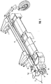
- Agricultural machine is mounted with a support frame 3 to a tractor, not shown.
- On the support frame 3 there is at least one support frame 10 about a vertical axis 12, 11 swiveling.
- On the support frame 10, 11 is a working unit designed as a mowing unit 4 height-adjustable by means of quadrilaterals 1 with ball joints.
- For Lateral guidance of the working unit 4 is provided at least one wishbone 2, which on the one hand with the support frame 3 of the support frame 10, 11 and on the other hand with the work unit 4 is articulated.
- the control arm 2 should be as long as possible and at an average working height of the working unit 4 approximately horizontal and right-angled to the direction of travel so that when the work unit moves 4 no or only slight lateral movements in transverse directions occur.
- the free end the support frame 10, 11 is supported by a ground wheel.
- On the bottom the support frame is an angular swivel gear 5 with a lower, rotatable gear part 9 provided.
- the axis of rotation of the gear part 9 is at least approximately aligned with the vertical axis 12.
- the bearing point of the rotatable gear part 9 in the angular gear is highly trained.
- An output stub 14 of the rotatable gear part 9 is over a propeller shaft 6 with the working unit 4 in drive connection.
- the wishbone 2 belongs to the guide device of the working unit 4 and is on the rotatable gear part 9 articulated via a horizontal hinge axis 8.
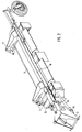
- the support frame 10, 11 is 90 ° to one Side swung out relative to the tractor, not shown, and only by drawing indicated locking device set.
- the wishbone 2 the Lateral forces of the working unit 4 on the angular swivel gear 5 on the support frame 3 transmits, is advantageously approximately parallel to the propeller shaft 6 when the work unit 4 moves in height, the change in length of the cardan shaft 6 kept low and wear of sliding parts is avoided.
- the wishbone 2 absorbs the reaction torque of the rotatable gear part 9 and ensures that whose output stub 14 both in the working position (Fig. 1) and in the transport position (Fig. 2) in the direction of the drive shaft of the working unit 4.
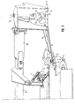
- Fig. 3 (working position) it can be seen that the of the articulation with the Quadrilateral joints 1 with their ball joints independent wishbones not only the Lateral forces of the working unit 4 supported on the support frame 3, but also as Torque support for the rotatable gear part 9 of the angular swivel gear 5 is designed.
- the wishbone 2 is only on the side of the work unit 4 a ball joint 7 is provided while at the other end of the wishbone 2 the horizontal hinge axis 8 the connection to the rotatable gear part 9 manufactures.
Landscapes
- Life Sciences & Earth Sciences (AREA)
- Environmental Sciences (AREA)
- Zoology (AREA)
- Engineering & Computer Science (AREA)
- Mechanical Engineering (AREA)
- Soil Sciences (AREA)
- Agricultural Machines (AREA)
- Harvester Elements (AREA)
Abstract
Description
- Fig. 1
- eine perspektivische Ansicht einer Landmaschine, die als Mähwerk ausgebildet ist, in der Arbeitsposition,
- Fig. 2
- eine Perspektivansicht der Landmaschine in der Transportstellung, und
- Fig. 3
- eine perspektivische Ansicht der Anlenkverbindung zwischen der Arbeitseinheit und dem Tragrahmen und einer Führungseinrichtung,
Claims (5)
- Führungseinrichtung für eine Landmaschine, die wenigstens einen mit eine Traggestell (3) an einen Schlepper oder dgl. anbaubaren, relativ zum Traggestell (3) um eine Hochachse (12) verschwenkbaren Tragrahmen (10, 11) und wenigstens eine daran über Verbindungselemente (1) höhenbeweglich angelenkte Arbeitseinheit (4) aufweist, wobei am Traggestell ein Winkelschwenkgetriebe (5) mit einem drehbaren Getriebeteil (9) angeordnet ist, dessen Drehstellung über eine Drehmomentstütze einstellbar ist, dadurch gekennzeichnet, dass die Verbindungselemente (1) in der Anlenkverbindung zwischen der Arbeitseinheit (4) und dem Tragrahmen (10, 11) auch relative Seitenbewegungen zwischen der Arbeitseinheit (4) und dem Tragrahmen (10, 11) zulassen, dass zur seitlichen Führung der Arbeitseinheit (4) in Richtung dieser Seitenbewegungen wenigstens ein von der Anlenkverbindung unabhängiger Querlenker (2) jeweils gelenkig mit der Arbeitseinheit (4) und dem Traggestell (3) des Tragrahmens (10, 11) verbunden ist, und dass der Querlenker (2) zusätzlich die die Drehstellung des drehbaren Getriebeteils (9) einstellbare Drehmomentstütze bildet.
- Führungseinrichtung nach Anspruch 1, dadurch gekennzeichnet, dass sich der Querlenker (2) von der Arbeitseinheit (4) zum Bereich der Hochachse (12) erstreckt.
- Führungseinrichtung nach Anspruch 1 und 2, dadurch gekennzeichnet, dass der Querlenker (2) im mittleren Arbeitshöhenbereich der Arbeitseinheit (4) in etwa waagrecht liegt, damit bei Höhenbewegungen der Arbeitseinheit keine oder nur geringfügige Querbewegungen entstehen.
- Führungseinrichtung nach Anspruch 1, dadurch gekennzeichnet, dass die Drehachse des Getriebeteils (9) zumindest in etwa mit der Hochachse (12) fluchtet.
- Führungseinrichtung nach wenigstens einem der Ansprüche 1 bis 4, dadurch gekennzeichnet, dass der Querlenker (2) mit einem Ende an der Arbeitseinheit (4) allseits gelenkig angelenkt und mit seinem anderen Ende um nur eine, vorzugsweise waagrechte, Gelenkachse (8) schwenkbar mit dem drehbaren Getriebeteil (9) verbunden ist, so dass der Querlenker (2) das Reaktionsmoment des Winkelschwenkgetriebes (5) aufnimmt, einen Abtriebsstummel (14) des drehbaren Getriebeteils (9) in eine für eine vom Getriebeteil (9) zur Arbeitseinheit (4) verlaufende Gelenkwelle (6) günstige Richtung einstellt und in den Seitenbewegungsrichtungen auftretende Reaktionskräfte der Arbeitseinheit über das Winkelschwenkgetriebe (5) auf das Traggestell (3) überträgt.
Applications Claiming Priority (2)
| Application Number | Priority Date | Filing Date | Title |
|---|---|---|---|
| DE29919025U | 1999-10-29 | ||
| DE29919025U DE29919025U1 (de) | 1999-10-29 | 1999-10-29 | Führungseinrichtung für eine Landmaschine, insbesondere ein Anbaumähwerk |
Publications (2)
| Publication Number | Publication Date |
|---|---|
| EP1095548A1 true EP1095548A1 (de) | 2001-05-02 |
| EP1095548B1 EP1095548B1 (de) | 2003-02-26 |
Family
ID=8080915
Family Applications (1)
| Application Number | Title | Priority Date | Filing Date |
|---|---|---|---|
| EP00123249A Expired - Lifetime EP1095548B1 (de) | 1999-10-29 | 2000-10-26 | Führungseinrichtung für eine Landmaschine |
Country Status (2)
| Country | Link |
|---|---|
| EP (1) | EP1095548B1 (de) |
| DE (2) | DE29919025U1 (de) |
Cited By (1)
| Publication number | Priority date | Publication date | Assignee | Title |
|---|---|---|---|---|
| DE202007015176U1 (de) * | 2007-10-31 | 2009-03-12 | Alois Pöttinger Maschinenfabrik Gmbh | Landmaschine |
Families Citing this family (1)
| Publication number | Priority date | Publication date | Assignee | Title |
|---|---|---|---|---|
| DE20010904U1 (de) | 2000-06-20 | 2000-09-28 | Fella-Werke GmbH & Co. KG, 90537 Feucht | Antriebsvorrichtung |
Citations (7)
| Publication number | Priority date | Publication date | Assignee | Title |
|---|---|---|---|---|
| DE3022742A1 (de) | 1979-06-19 | 1981-01-15 | Kuhn Sa | Traggestell fuer landwirtschaftliche maschinen |
| DE8701093U1 (de) | 1987-01-23 | 1987-03-26 | Maschinenfabriken Bernard Krone Gmbh, 4441 Spelle | Traggestell für eine landwirtschaftliche Maschine |
| NL8700863A (nl) * | 1987-04-13 | 1988-11-01 | Multinorm Bv | Landbouwwerktuig voorzien van een verbeterd gestel, alsmede maaibalk daarvoor. |
| DE8906546U1 (de) | 1989-05-27 | 1989-07-06 | Fella-Werke Gmbh, 8501 Feucht | Vorrichtung zum Anbau eines Mähwerks |
| US4848069A (en) * | 1986-12-22 | 1989-07-18 | Kuhn, S.A. | Mower |
| US5199249A (en) * | 1990-11-12 | 1993-04-06 | Kuhn, S.A. | Farm machine adaptable to the contour of the land and having a pivoting housing |
| EP0678237A1 (de) * | 1994-04-21 | 1995-10-25 | Jf-Fabriken - J. Freudendahl A/S | Gezogenes landwirtschaftliches Gerät |
-
1999
- 1999-10-29 DE DE29919025U patent/DE29919025U1/de not_active Expired - Lifetime
-
2000
- 2000-10-26 EP EP00123249A patent/EP1095548B1/de not_active Expired - Lifetime
- 2000-10-26 DE DE50001319T patent/DE50001319D1/de not_active Expired - Lifetime
Patent Citations (7)
| Publication number | Priority date | Publication date | Assignee | Title |
|---|---|---|---|---|
| DE3022742A1 (de) | 1979-06-19 | 1981-01-15 | Kuhn Sa | Traggestell fuer landwirtschaftliche maschinen |
| US4848069A (en) * | 1986-12-22 | 1989-07-18 | Kuhn, S.A. | Mower |
| DE8701093U1 (de) | 1987-01-23 | 1987-03-26 | Maschinenfabriken Bernard Krone Gmbh, 4441 Spelle | Traggestell für eine landwirtschaftliche Maschine |
| NL8700863A (nl) * | 1987-04-13 | 1988-11-01 | Multinorm Bv | Landbouwwerktuig voorzien van een verbeterd gestel, alsmede maaibalk daarvoor. |
| DE8906546U1 (de) | 1989-05-27 | 1989-07-06 | Fella-Werke Gmbh, 8501 Feucht | Vorrichtung zum Anbau eines Mähwerks |
| US5199249A (en) * | 1990-11-12 | 1993-04-06 | Kuhn, S.A. | Farm machine adaptable to the contour of the land and having a pivoting housing |
| EP0678237A1 (de) * | 1994-04-21 | 1995-10-25 | Jf-Fabriken - J. Freudendahl A/S | Gezogenes landwirtschaftliches Gerät |
Cited By (1)
| Publication number | Priority date | Publication date | Assignee | Title |
|---|---|---|---|---|
| DE202007015176U1 (de) * | 2007-10-31 | 2009-03-12 | Alois Pöttinger Maschinenfabrik Gmbh | Landmaschine |
Also Published As
| Publication number | Publication date |
|---|---|
| DE50001319D1 (de) | 2003-04-03 |
| EP1095548B1 (de) | 2003-02-26 |
| DE29919025U1 (de) | 2000-02-03 |
Similar Documents
| Publication | Publication Date | Title |
|---|---|---|
| DE69017363T2 (de) | Mähmaschine mit verbesserter Entlastungsvorrichtung. | |
| DE2053073C3 (de) | Mähmaschine | |
| DE3930811B4 (de) | Vorrichtung zur Bodenanpassung der Arbeitswerkzeuge von Heumaschinen | |
| DE2814440A1 (de) | Erntemaschine | |
| DE3702221A1 (de) | Maehmaschine | |
| EP0807377A2 (de) | Vorrichtung zum Anschliessen eines aus der Arbeitsstellung in eine Transportstellung höhenverstellbares Gerätes an ein Fahrzeug | |
| EP2532221A1 (de) | Mähdeck | |
| DE2410453A1 (de) | Heuwerbungsmaschine | |
| DE9213091U1 (de) | Kreiselegge | |
| EP0289773B1 (de) | Landwirtschaftliches Anhängegerät | |
| DE69307127T2 (de) | Heuwendemaschine | |
| EP0945051B1 (de) | Mähmaschine | |
| EP0512326B1 (de) | Verwendung einer lösbaren Flanschverbindung an einer Deichsel und gezogene Erntemaschine | |
| EP0630554B2 (de) | Frei schwenkbare Nachlaufräder für landwirtschaftliche Arbeitsmaschinen, insbesondere Kreiselheumaschinen | |
| EP0950347B1 (de) | Heuwerbungsmaschine | |
| DE69512559T2 (de) | Heuwerbungsmaschine, insbesondere ein Schwader für Futter | |
| DE19620063A1 (de) | Aufhängung und Antriebsanordnung für ein- oder beidseitig an einem Trägerfahrzeug angebrachte Arbeitsaggregate | |
| EP1095548B1 (de) | Führungseinrichtung für eine Landmaschine | |
| DE69304558T2 (de) | Heuwerbungsmaschine mit einem mit gesteuerten Stützrädern versehenen Rahmen | |
| DE29708799U1 (de) | Mehrkreiseliger Großschwader | |
| DE3835367C2 (de) | Vorrichtung für Mähwerke zur Bodenanpassung der Schneidwerke | |
| DE4142496C2 (de) | Heuwerbungsmaschine | |
| DE602005005143T2 (de) | Heuwerbungsmaschine | |
| DE4112155C1 (de) | ||
| DE9417893U1 (de) | Mähmaschine |
Legal Events
| Date | Code | Title | Description |
|---|---|---|---|
| PUAI | Public reference made under article 153(3) epc to a published international application that has entered the european phase |
Free format text: ORIGINAL CODE: 0009012 |
|
| AK | Designated contracting states |
Kind code of ref document: A1 Designated state(s): DE FR NL |
|
| AX | Request for extension of the european patent |
Free format text: AL;LT;LV;MK;RO;SI |
|
| 17P | Request for examination filed |
Effective date: 20010326 |
|
| GRAG | Despatch of communication of intention to grant |
Free format text: ORIGINAL CODE: EPIDOS AGRA |
|
| 17Q | First examination report despatched |
Effective date: 20010828 |
|
| GRAG | Despatch of communication of intention to grant |
Free format text: ORIGINAL CODE: EPIDOS AGRA |
|
| AKX | Designation fees paid |
Free format text: DE FR NL |
|
| GRAG | Despatch of communication of intention to grant |
Free format text: ORIGINAL CODE: EPIDOS AGRA |
|
| GRAH | Despatch of communication of intention to grant a patent |
Free format text: ORIGINAL CODE: EPIDOS IGRA |
|
| 111Z | Information provided on other rights and legal means of execution |
Free format text: 20020412 DE FR NL |
|
| GRAH | Despatch of communication of intention to grant a patent |
Free format text: ORIGINAL CODE: EPIDOS IGRA |
|
| GRAA | (expected) grant |
Free format text: ORIGINAL CODE: 0009210 |
|
| AK | Designated contracting states |
Designated state(s): DE FR NL |
|
| REF | Corresponds to: |
Ref document number: 50001319 Country of ref document: DE Date of ref document: 20030403 Kind code of ref document: P |
|
| ET | Fr: translation filed | ||
| PLBE | No opposition filed within time limit |
Free format text: ORIGINAL CODE: 0009261 |
|
| STAA | Information on the status of an ep patent application or granted ep patent |
Free format text: STATUS: NO OPPOSITION FILED WITHIN TIME LIMIT |
|
| 26N | No opposition filed |
Effective date: 20031127 |
|
| NLS | Nl: assignments of ep-patents |
Owner name: FELLA-WERKE GMBH Effective date: 20080108 Owner name: FELLA BETEILIGUNGS GMBH Effective date: 20080108 |
|
| REG | Reference to a national code |
Ref country code: FR Ref legal event code: TP |
|
| REG | Reference to a national code |
Ref country code: FR Ref legal event code: PLFP Year of fee payment: 16 |
|
| REG | Reference to a national code |
Ref country code: DE Ref legal event code: R082 Ref document number: 50001319 Country of ref document: DE Representative=s name: GRUENECKER PATENT- UND RECHTSANWAELTE PARTG MB, DE Ref country code: DE Ref legal event code: R081 Ref document number: 50001319 Country of ref document: DE Owner name: AGCO FEUCHT GMBH, DE Free format text: FORMER OWNER: FELLA-WERKE GMBH, 90537 FEUCHT, DE |
|
| REG | Reference to a national code |
Ref country code: NL Ref legal event code: HC Owner name: AGCO FEUCHT GMBH; DE Free format text: DETAILS ASSIGNMENT: VERANDERING VAN EIGENAAR(S), VERANDERING VAN NAAM VAN DE EIGENAAR(S); FORMER OWNER NAME: FELLA-WERKE GMBH Effective date: 20160802 |
|
| REG | Reference to a national code |
Ref country code: FR Ref legal event code: PLFP Year of fee payment: 17 |
|
| PGFP | Annual fee paid to national office [announced via postgrant information from national office to epo] |
Ref country code: DE Payment date: 20161020 Year of fee payment: 17 Ref country code: FR Payment date: 20161020 Year of fee payment: 17 Ref country code: NL Payment date: 20161019 Year of fee payment: 17 |
|
| REG | Reference to a national code |
Ref country code: DE Ref legal event code: R119 Ref document number: 50001319 Country of ref document: DE |
|
| REG | Reference to a national code |
Ref country code: NL Ref legal event code: MM Effective date: 20171101 |
|
| REG | Reference to a national code |
Ref country code: FR Ref legal event code: ST Effective date: 20180629 |
|
| PG25 | Lapsed in a contracting state [announced via postgrant information from national office to epo] |
Ref country code: DE Free format text: LAPSE BECAUSE OF NON-PAYMENT OF DUE FEES Effective date: 20180501 Ref country code: NL Free format text: LAPSE BECAUSE OF NON-PAYMENT OF DUE FEES Effective date: 20171101 |
|
| PG25 | Lapsed in a contracting state [announced via postgrant information from national office to epo] |
Ref country code: FR Free format text: LAPSE BECAUSE OF NON-PAYMENT OF DUE FEES Effective date: 20171031 |