EP1095597A2 - Dispositif de stabilisation destiné à des housses et des coussins placés sur des meubles capitonnés et du type fauteuil - Google Patents
Dispositif de stabilisation destiné à des housses et des coussins placés sur des meubles capitonnés et du type fauteuil Download PDFInfo
- Publication number
- EP1095597A2 EP1095597A2 EP01100667A EP01100667A EP1095597A2 EP 1095597 A2 EP1095597 A2 EP 1095597A2 EP 01100667 A EP01100667 A EP 01100667A EP 01100667 A EP01100667 A EP 01100667A EP 1095597 A2 EP1095597 A2 EP 1095597A2
- Authority
- EP
- European Patent Office
- Prior art keywords
- stablising
- elongated member
- fabric cover
- stabilizing device
- elastic material
- Prior art date
- Legal status (The legal status is an assumption and is not a legal conclusion. Google has not performed a legal analysis and makes no representation as to the accuracy of the status listed.)
- Granted
Links
- 230000000087 stabilizing effect Effects 0.000 title claims abstract description 51
- 239000004744 fabric Substances 0.000 claims abstract description 23
- 239000013013 elastic material Substances 0.000 claims abstract description 11
- 230000003019 stabilising effect Effects 0.000 claims abstract 5
- 239000000463 material Substances 0.000 claims description 8
- 239000004800 polyvinyl chloride Substances 0.000 claims description 4
- 239000000853 adhesive Substances 0.000 claims description 3
- 230000001070 adhesive effect Effects 0.000 claims description 3
- 229910003460 diamond Inorganic materials 0.000 claims description 3
- 239000010432 diamond Substances 0.000 claims description 3
- 229920000915 polyvinyl chloride Polymers 0.000 claims description 3
- 239000011248 coating agent Substances 0.000 claims 2
- 238000000576 coating method Methods 0.000 claims 2
- 238000001125 extrusion Methods 0.000 description 2
- 238000009963 fulling Methods 0.000 description 2
- 238000004519 manufacturing process Methods 0.000 description 2
- 238000012986 modification Methods 0.000 description 2
- 230000004048 modification Effects 0.000 description 2
- 206010048961 Localised oedema Diseases 0.000 description 1
- 239000004793 Polystyrene Substances 0.000 description 1
- 238000000071 blow moulding Methods 0.000 description 1
- 229910052799 carbon Inorganic materials 0.000 description 1
- 230000000694 effects Effects 0.000 description 1
- 229920002457 flexible plastic Polymers 0.000 description 1
- 238000001746 injection moulding Methods 0.000 description 1
- 238000003780 insertion Methods 0.000 description 1
- 230000037431 insertion Effects 0.000 description 1
- 238000000465 moulding Methods 0.000 description 1
- 229920002223 polystyrene Polymers 0.000 description 1
- 230000001681 protective effect Effects 0.000 description 1
- 239000007787 solid Substances 0.000 description 1
- 239000003381 stabilizer Substances 0.000 description 1
- 229920001169 thermoplastic Polymers 0.000 description 1
- 229920001187 thermosetting polymer Polymers 0.000 description 1
- 239000004416 thermosoftening plastic Substances 0.000 description 1
Images



Classifications
-
- B—PERFORMING OPERATIONS; TRANSPORTING
- B25—HAND TOOLS; PORTABLE POWER-DRIVEN TOOLS; MANIPULATORS
- B25G—HANDLES FOR HAND IMPLEMENTS
- B25G1/00—Handle constructions
- B25G1/10—Handle constructions characterised by material or shape
- B25G1/102—Handle constructions characterised by material or shape the shape being specially adapted to facilitate handling or improve grip
-
- A—HUMAN NECESSITIES
- A47—FURNITURE; DOMESTIC ARTICLES OR APPLIANCES; COFFEE MILLS; SPICE MILLS; SUCTION CLEANERS IN GENERAL
- A47L—DOMESTIC WASHING OR CLEANING; SUCTION CLEANERS IN GENERAL
- A47L13/00—Implements for cleaning floors, carpets, furniture, walls, or wall coverings
- A47L13/02—Scraping
- A47L13/022—Scraper handles
-
- A—HUMAN NECESSITIES
- A47—FURNITURE; DOMESTIC ARTICLES OR APPLIANCES; COFFEE MILLS; SPICE MILLS; SUCTION CLEANERS IN GENERAL
- A47L—DOMESTIC WASHING OR CLEANING; SUCTION CLEANERS IN GENERAL
- A47L13/00—Implements for cleaning floors, carpets, furniture, walls, or wall coverings
- A47L13/10—Scrubbing; Scouring; Cleaning; Polishing
- A47L13/42—Details
-
- A—HUMAN NECESSITIES
- A62—LIFE-SAVING; FIRE-FIGHTING
- A62B—DEVICES, APPARATUS OR METHODS FOR LIFE-SAVING
- A62B3/00—Devices or single parts for facilitating escape from buildings or the like, e.g. protection shields, protection screens; Portable devices for preventing smoke penetrating into distinct parts of buildings
- A62B3/005—Rescue tools with forcing action
-
- Y—GENERAL TAGGING OF NEW TECHNOLOGICAL DEVELOPMENTS; GENERAL TAGGING OF CROSS-SECTIONAL TECHNOLOGIES SPANNING OVER SEVERAL SECTIONS OF THE IPC; TECHNICAL SUBJECTS COVERED BY FORMER USPC CROSS-REFERENCE ART COLLECTIONS [XRACs] AND DIGESTS
- Y10—TECHNICAL SUBJECTS COVERED BY FORMER USPC
- Y10S—TECHNICAL SUBJECTS COVERED BY FORMER USPC CROSS-REFERENCE ART COLLECTIONS [XRACs] AND DIGESTS
- Y10S16/00—Miscellaneous hardware, e.g. bushing, carpet fastener, caster, door closer, panel hanger, attachable or adjunct handle, hinge, window sash balance
- Y10S16/18—Composition handles
-
- Y—GENERAL TAGGING OF NEW TECHNOLOGICAL DEVELOPMENTS; GENERAL TAGGING OF CROSS-SECTIONAL TECHNOLOGIES SPANNING OVER SEVERAL SECTIONS OF THE IPC; TECHNICAL SUBJECTS COVERED BY FORMER USPC CROSS-REFERENCE ART COLLECTIONS [XRACs] AND DIGESTS
- Y10—TECHNICAL SUBJECTS COVERED BY FORMER USPC
- Y10T—TECHNICAL SUBJECTS COVERED BY FORMER US CLASSIFICATION
- Y10T24/00—Buckles, buttons, clasps, etc.
- Y10T24/33—Buckles, buttons, clasps, etc. having adhesive fastener
-
- Y—GENERAL TAGGING OF NEW TECHNOLOGICAL DEVELOPMENTS; GENERAL TAGGING OF CROSS-SECTIONAL TECHNOLOGIES SPANNING OVER SEVERAL SECTIONS OF THE IPC; TECHNICAL SUBJECTS COVERED BY FORMER USPC CROSS-REFERENCE ART COLLECTIONS [XRACs] AND DIGESTS
- Y10—TECHNICAL SUBJECTS COVERED BY FORMER USPC
- Y10T—TECHNICAL SUBJECTS COVERED BY FORMER US CLASSIFICATION
- Y10T24/00—Buckles, buttons, clasps, etc.
- Y10T24/44—Clasp, clip, support-clamp, or required component thereof
- Y10T24/44034—Dissociable gripping members
- Y10T24/44043—Channel and inserted bar
- Y10T24/4406—Resilient channel or bar
Definitions
- the present invention relates generally to stabilizing devices for securing fabric covers on furniture. More specifically, the present invention relates to an elongated stabilizing device having a V-shaped cross section.
- the use of fabric throw covers on upholstered furniture has become very popular in recent years.
- the throw covers can vary in size ranging from, for example, a 100" by 90" cover for chairs to a 100" by 170" cover for large sofas.
- problems quickly arise due to the normal use of the furniture. In other words, the normal movements of a person such as sitting, adjusting one's position while seating, and/or getting up from the sitting position all tend to displace the position of the throw cover.
- the appearance of the throw cover quickly becomes unsightly because it is wrinkled, bunched up and out of place. Accordingly, to maintain the proper and desired position for the throw cover, the user must continuously adjust smooth and retuck the throw cover.
- U.S. Patent No. 517,306 discloses a device for fastening slip covers on upholstered furniture.
- the device includes several clip like relatively narrow fasteners B that are connected to a rod F.
- Each fastener has teeth E 4 at the end of arms E 2 .
- the teeth E 4 penetrate into the slip cover C and the cushions A, B.
- this type of device will immediately damage and eventually destroy the slip cover C, as well as the cushions A, B by making holes in each.
- this device is quite cumbersome to insert because each clip must be simultaneously compressed. Otherwise, the teeth may each on the fabric of the cover and/or the cushions.
- This device is also difficult to remove once in place because each clip must be individually compressed and disengaged from the cushions and the slip cover, and then all of the compressed clips must be removed simultaneously.
- Other problems with this device are that the fastener can be easily moved out of position, i.e., dislodged, if the slip cover is moved laterally, and that multiple fasteners must be used along each length.
- an object of the present invention to provide a stabilizing device that permits the cover to be initially tucked in place on the upholstered furniture in a desired position and thereafter prevents its relative movement with respect to the upholstered furniture during the normal use while simultaneously preventing damage to the throw cover. It is a further object for an elongated stabilizing device to be used, one preferably made of an elastic material to hold the slip cover uniformly along the edge of the fabric so that there is a reduced tendency to tear or deform the fabric. It is a still further object to permit the use of a single continuous one piece unitary stabilizing device for each length of cushion to be tucked in place.
- the stabilizing device includes an elongated member having a pair of arms forming the V-sbape.
- the member is preferably made of an elasticity such that pair of arms are collapsible from a first naturally open stable position to a second unstable closed position without undue force.
- the stabilizing device is an elongated member and has a V-shaped cross section as illustrated in Figures 3A through 3E.
- the elongated member has a nose section 12 and a pair of arm sections 14, 16, which forms the V-shape.
- the elongated member is preferably made of an elastic material, such that the material has an elasticity to ensure that the pair of arms are moveable with a moderate amount of force from a first naturally open or stable position, as illustrated in Figures 2 and 3A-3E, to a second closed unstable position when the elongated member is being installed between adjacent furniture cushions 21 as illustrated in Figure 5.
- the elasticity will of course vary depending upon the dimensions of the elongated member. However, the elasticity can be easily determined by one skilled in the art such that the member is sufficiently elastic to enable insertion without undue force and to maintain pressure on the fabric cover and cushion while not dislodging the cushion from its intended position. This elasticity is necessary to enable the member to be inserted with minimal force and after the member is in place, to permit the member to return to or towards its open position to continually apply force to the fabric and cushion because the internal forces in the member urge it back towards the initial stable position.
- the outer surfaces 22, 24 of each arm 14, 16 have a plurality of ribbed projections 26 that are integrally formed with the outer edge to prevent the fabric cover 30 from moving with respect to the stabilizing device. While it is preferred that the ribbed projections 26 be on both outer surfaces 22, 24, the ribbed projections 26 can be disposed on only one of the arms as illustrated in Figures 1, 2 and 3A or not used at all as illustrated in Figure 3B and 3E. In addition, the ribbed projections 26 can be disposed on the outer surface of any of the embodiments of the present invention. As stated above, the ribbed projections 26 are designed to prevent the fabric cover from moving with respect to the stabilizing device.
- the surfaces 22, 24 can be coated with a tacky or an adhesive material, which would perform the same function as the ribbed projections 26.
- a strip of two-sided tape can be attached to each of the outer surfaces 22, 24. Immediately prior to use, the user can remove a protective strip of wax type paper from the outer surface of the two-sided tape.
- FIG. 3B illustrates the basic design for the present invention.
- Figure 3C illustrates another embodiment of the stabilizing device where the outer surfaces 22, 24 of the arms 14, 16 have a continuous ribbed section 26.
- the embodiment illustrated in Figure 3C will impart a greater resistance upon the fabric cover 30 than the embodiment illustrated in Figure 3B.
- one of the arms 16 may have one or more V-shaped notches 50 cut out from outer surface 26.
- the cut out notches 50 permit the device to be tucked into non-linear contours of furniture.
- the arm containing the cut out notch is preferably placed along the concave portion of the carve so that it may compress along the curve.
- the stabilizing device is a hollow elongated member having a nose 12 and arms 14, 16.
- the core section 28 of the elongated device has a hollow cylindrical shape.
- a fastener member 42 or hook member can be inserted into the axial open ends of the core 28.
- a cord, strap, chain or other type of tie 44 can be attached to the stabilizing device at one end and to a specialty cushion, such as a lumbar cushion bolster 46, at the other end of the tie (see Figures 8 and 9).
- the core portion 28 has a follow cylindrical shape. This open core allows the arms 14, 16 of the elongated member to be connected to an adjacent elongated member or any other structure by simply making a mechanical connection with the open axial end of the core 28.
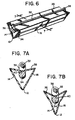
- Figures 6, 7A and 7B illustrate another embodiment of the present invention.
- a pair of elongated bar members 32, 34 are attached to the elongated member.
- the bar members 32, 34 are rigidly coupled to one another by a pair of links 36 disposed at each axial end of the bar members 32, 34.
- bar member 34 is attached to a rear wall portion 38 of the elongated member along an arc shaped section 40.
- the stabilizing device of the present invention is preferably made by extrusion.
- the stabilizing device can also be made by cold-molding, co-extrusion, blow molding or even by injection molding.
- the stabilizing device can be made from flexible plastic or elastic material.
- the stabilizing device can be made from polyvinylchloride (pvc), thermoplastic or thermosetting rubber or polystyrene.
- the nose 12 of the elongated member can include a core portion 28.
- a shore A durometer hardness of the core portion 28 ranges from 70 to 80
- the remainder of the elongated member, including the arms 14, 16 preferably has a shore A hardness ranging from 50 to 90.
- the core section is more rigid than the pair of arms 14, 16.
- This core section with increased stiffness with respect to the arm sections, helps increase the torsional resistance of the stabilizing device while maintaining the flexibility of the arm sections to move from a first natural open position to a second closed position.
- the elongated member can comprise three different sections each having a different shore A durometer hardness.
- the arm sections 14, 16 can have a shore A durometer hardness ranging from 70 to 80, the tip of the arms can range from 60-70, and the core section 28 can range from 85 to 95.
- the elongated member is made from a material having a uniform hardness.
- the shore A durometer hardness may range from 45 to 105 with a preferred range for polyvinylchloride being from 50 to 85. In fact, in one embodiment the shore A durometer hardness is about 76.
- the shape of the elongated member of the present invention is not limited to a V-shape and can take on various different shapes in cross-section such as an X-shape or the cross-sections illustrated in Figures 10A-10G.
- the elongated member 110 has a closed shape.
- the embodiments in Figures 10A, 10B and 10C are triangular in shape
- the embodiments in Figures 10D, 10E and 10F are diamond shaped in cross-section
- the embodiment illustrated in Figure 10G is circular in cross-section.
- the embodiments illustrated in Figures 10C and 10F are solid and the embodiments illustrated in Figures 10A, 10B, 10D, 10B and 10G are hollow.
- any of these embodiments can include the ribbed shaped projections 26 that are currently illustrated in the embodiments of Figures 10A, 10B, 10F and 10G.
- the embodiment illustrated in Figure 10E includes nose sections 112 disposed at each of its corners.
- the nose sections 112 can be made of a softer material than the remainder of the elongated member.
- the use of the stabilizing device according to the present invention will be described below with reference to Figures 2 and 5. The user first places the throw cover 30 on the furniture. The user then places the stabilizing device 10 at the intersection between adjacent cushions 21 with the nose 12 of the elongated member pointing at the intersection and the nose and the outer surfaces 22, 24 of the arms 14, 16 being in contact with the cover 30.
- the cover 30 is disposed between the stabilizing device 10 and the cushions 21.
- the stabilizing device is preferably a single one piece device whose length is approximately equal to the cushion length. The user then tucks the stabilizing device and cover into the space between the adjacent cushions through the use of a spatula type tool 20 as illustrated in Figure 5. As the cover is being tucked into place, the resilient arms 14, 16 of the stabilizing device move from the first natural open position to a second closed position. The entire length of the stabilizing device need not be tucked in simultaneously. The device can be tucked in sequentially by starting at one end and, in an accordance type manner, move toward the other end of the elongated device.
- the device is preferably flexible in the longitudinal direction to effect such a sequential tucking.
- the stabilizing device can be made from a relatively rigid material which would not permit a sequential tucking.
- the arms 14, 16 of the elongated member contact the outer edges 18 of a tool 20. If one were not using a tool to install the elongated member, the arms 14, 16 might actually contact each other.
- the pair of arms 14, 16 are moved closer or become adjacent to one another, and in the first open position, the pair of arms 14, 16 are spaced apart from one another, as illustrated in Fig. 2.
- the user simply removes the tool, leaving the stabilizing device and cover 30 in the space between the adjacent cushions 21 as illustrated in Figure 2.
- the user then proceeds to insert the remaining stabilizing devices into the remaining adjoining cushion intersections.
- a chair will require the use of three stabilizing devices.
- One stabilizing device will be placed at the intersection between the seat cushion and the chair back and the remaining two stabilizing devices, are placed at the intersections between the seat cushion and the sides of the chair. It follows that a love seat will generally require four stabilizing devices and a sofa will require five stabilizing devices.
- the stabilizing device itself will generally have a length approximating that of the cushion width.
- the stabilizing device will preferably be at least 4" long, and most desirably about 18" to 24" in length.
- the length of the outer surface of each arm may have a width ranging from 1 ⁇ 2" to 3", with a preferable length of approximately 1 3 ⁇ 4". Therefore, the preferred dimensions of the elongated member are 1 3 ⁇ 4" x 1 3 ⁇ 4" x 18" or 1 3 ⁇ 4 x 1 3 ⁇ 4" x 24".
- the stabilizer is preferably made of a material which can easily be cut to length by me user.
Landscapes
- Engineering & Computer Science (AREA)
- Mechanical Engineering (AREA)
- Health & Medical Sciences (AREA)
- General Health & Medical Sciences (AREA)
- Business, Economics & Management (AREA)
- Emergency Management (AREA)
- Mattresses And Other Support Structures For Chairs And Beds (AREA)
- Invalid Beds And Related Equipment (AREA)
- Cleaning Implements For Floors, Carpets, Furniture, Walls, And The Like (AREA)
- Seats For Vehicles (AREA)
Applications Claiming Priority (3)
| Application Number | Priority Date | Filing Date | Title |
|---|---|---|---|
| US270057 | 1994-07-01 | ||
| US08/270,057 US5547249A (en) | 1994-07-01 | 1994-07-01 | Stabilizing device for use with covers and cushions on seating and upholstered furniture |
| EP95928172A EP0765129B1 (fr) | 1994-07-01 | 1995-07-03 | Dispositif de stabilisation destine a des housses et des coussins places sur des meubles capitonnes et du type fauteuil |
Related Parent Applications (1)
| Application Number | Title | Priority Date | Filing Date |
|---|---|---|---|
| EP95928172A Division EP0765129B1 (fr) | 1994-07-01 | 1995-07-03 | Dispositif de stabilisation destine a des housses et des coussins places sur des meubles capitonnes et du type fauteuil |
Publications (3)
| Publication Number | Publication Date |
|---|---|
| EP1095597A2 true EP1095597A2 (fr) | 2001-05-02 |
| EP1095597A3 EP1095597A3 (fr) | 2001-06-20 |
| EP1095597B1 EP1095597B1 (fr) | 2004-12-08 |
Family
ID=23029722
Family Applications (2)
| Application Number | Title | Priority Date | Filing Date |
|---|---|---|---|
| EP01100667A Expired - Lifetime EP1095597B1 (fr) | 1994-07-01 | 1995-07-03 | Dispositif de stabilisation destiné à des housses et des coussins placés sur des meubles capitonnés et du type fauteuil |
| EP95928172A Expired - Lifetime EP0765129B1 (fr) | 1994-07-01 | 1995-07-03 | Dispositif de stabilisation destine a des housses et des coussins places sur des meubles capitonnes et du type fauteuil |
Family Applications After (1)
| Application Number | Title | Priority Date | Filing Date |
|---|---|---|---|
| EP95928172A Expired - Lifetime EP0765129B1 (fr) | 1994-07-01 | 1995-07-03 | Dispositif de stabilisation destine a des housses et des coussins places sur des meubles capitonnes et du type fauteuil |
Country Status (8)
| Country | Link |
|---|---|
| US (2) | US5547249A (fr) |
| EP (2) | EP1095597B1 (fr) |
| AU (1) | AU681311B2 (fr) |
| BR (1) | BR9508707A (fr) |
| DE (2) | DE69533843T2 (fr) |
| GB (1) | GB2296860B (fr) |
| MX (1) | MX9606640A (fr) |
| WO (1) | WO1996001063A1 (fr) |
Cited By (1)
| Publication number | Priority date | Publication date | Assignee | Title |
|---|---|---|---|---|
| FR2852296A1 (fr) * | 2003-04-02 | 2004-09-17 | Proton Professional Toner | Dispositif de positionnement d'une bande d'etancheite, bande d'etancheite adaptee et procede de travail correspondant |
Families Citing this family (47)
| Publication number | Priority date | Publication date | Assignee | Title |
|---|---|---|---|---|
| US5722723A (en) * | 1994-07-01 | 1998-03-03 | Presicent Partners, Lp | Stabilizing device for slipcovers |
| US5632068A (en) * | 1995-04-06 | 1997-05-27 | Prescient Partners, L.P. | Device for shaping and maintaining the position of skirts and covers on seating and upholstered furniture |
| US5957528A (en) * | 1997-12-24 | 1999-09-28 | Campbell; Kelly K. | Seat cover |
| DE19808995C1 (de) | 1998-03-03 | 1999-05-20 | Binder Gottlieb Gmbh & Co | Befestigungssystem für einen Fahrzeugsitz |
| US6735840B2 (en) * | 1998-03-04 | 2004-05-18 | Megaware Keelguard, Inc. | Burnishing tool |
| US6022072A (en) * | 1998-04-02 | 2000-02-08 | Moyer; Lee Beth | Debris collector for upholstered furniture |
| US6263578B1 (en) | 1999-09-27 | 2001-07-24 | In-N-Out Burgers | Ergonomic griddle scraping tool |
| US6397711B1 (en) * | 2000-01-20 | 2002-06-04 | Kenneth Irvin Marek | Hand tool |
| GB0004892D0 (en) | 2000-03-01 | 2000-04-19 | Zamuner Frank | Ergonomic handle attachment for welding torch |
| GB0015774D0 (en) * | 2000-06-28 | 2000-08-16 | Reckitt & Colmann Prod Ltd | Appliance |
| US6487747B2 (en) | 2001-01-10 | 2002-12-03 | Kaminstein Imports, Inc. | Curved handle for long handled tools |
| US6637180B2 (en) * | 2001-03-16 | 2003-10-28 | Michael Gullotti | Hand tool having a flexible handle member |
| USD467697S1 (en) | 2001-10-15 | 2002-12-24 | Michael Spadafora | Wastebasket hold down attachment |
| US6709054B2 (en) | 2002-01-22 | 2004-03-23 | Prescient Partners, L.P. | Slipcover wrapping technique |
| USD487685S1 (en) | 2002-05-14 | 2004-03-23 | Magic American Products, Inc. | Combined scraper, spreader and finishing tool |
| US20040055099A1 (en) * | 2002-09-23 | 2004-03-25 | Greenberg William A. | Ergonomic handle system for tool head |
| USD536178S1 (en) | 2003-09-05 | 2007-02-06 | Greenberg William A | Handle |
| US20080131842A1 (en) * | 2003-10-14 | 2008-06-05 | Steven Joseph Edwards | Multiple grip dental handle |
| US20050100627A1 (en) * | 2003-11-06 | 2005-05-12 | Mckinney W. Richardson | Potter's throwing tool |
| US6918321B1 (en) * | 2004-03-08 | 2005-07-19 | William Whittaker | Shingle ripper |
| US20050223499A1 (en) * | 2004-04-09 | 2005-10-13 | Bruce Baker | Ergonomic hand tools, construction thereof, and packaging therefor |
| US20050241110A1 (en) | 2004-04-09 | 2005-11-03 | Bruce Baker | Ergonomic handles, especially for garden tools |
| US7258399B2 (en) * | 2005-08-19 | 2007-08-21 | Paula S Neustat | Slipcover with integrated padded and decorative component |
| US20060175883A1 (en) * | 2005-02-04 | 2006-08-10 | Neustat Paula S | Slipcover with integrated padded and decorative component |
| USD552799S1 (en) * | 2005-07-14 | 2007-10-09 | James Williams | Contoured back scratcher |
| US20070180703A1 (en) * | 2006-02-07 | 2007-08-09 | Sierra Diana B | Hair removal device |
| USD558396S1 (en) * | 2006-02-07 | 2007-12-25 | Helen Of Troy Limited | Hair removal device |
| US20080034525A1 (en) * | 2006-08-09 | 2008-02-14 | A. Richard S.E.N.C. | Wallpaper scraper |
| DE102007053009B4 (de) * | 2007-04-04 | 2016-05-12 | Johnson Controls Gmbh | Befestigungsanordnung für einen Sitzbezug, insbesondere eines Fahrzeugsitzes, sowie ein Montageverfahren |
| US7677662B2 (en) * | 2007-10-03 | 2010-03-16 | Kevin Thompson | Removable, reversible, protective hammock-style seat cover |
| US7900538B2 (en) * | 2008-10-14 | 2011-03-08 | Breaching Technologies, Inc. | Packable battering ram |
| CA2650345A1 (fr) | 2008-11-07 | 2010-05-07 | Brian T. Clancy | Poignee ergonomique utilitaire sport |
| US20100148563A1 (en) * | 2008-12-11 | 2010-06-17 | Katchall4U Inc. | Catching device for use with upholstered furniture |
| US7931335B1 (en) * | 2009-06-23 | 2011-04-26 | Bergan, Llc | Car seat protector with chassis lock system |
| US8393675B2 (en) * | 2009-12-15 | 2013-03-12 | Kevin Swanson | Furniture protection systems and method |
| US8641311B2 (en) | 2010-10-11 | 2014-02-04 | The Procter & Gamble Company | Cleaning head for a target surface |
| US8763192B2 (en) | 2011-03-28 | 2014-07-01 | The Procter & Gamble Company | Starch head having a stiffening member |
| US20120246854A1 (en) | 2011-03-28 | 2012-10-04 | Hirotaka Uchiyama | Water Disposable Head Comprising Plural Water Disposable Materials |
| US8726444B2 (en) | 2011-03-28 | 2014-05-20 | The Procter & Gamble Company | Starch head for cleaning a target surface |
| US9157271B2 (en) * | 2011-05-28 | 2015-10-13 | Burton, Fastener Distributing LLC | Spline for screen framing |
| USD676732S1 (en) * | 2011-08-31 | 2013-02-26 | Labplas Inc. | Handle for holding a sampling sponge |
| US9661930B2 (en) | 2012-09-21 | 2017-05-30 | Steelcase Inc. | Chair construction |
| US10000143B1 (en) | 2015-11-04 | 2018-06-19 | Christopher Linnel | Debris catching system for a child seat |
| US10710122B2 (en) | 2016-03-23 | 2020-07-14 | Hal P. Greenberger | Material removal from surfaces |
| US20180064165A1 (en) * | 2016-09-02 | 2018-03-08 | Four Twenty One, LLC | Herb scoop |
| US10660452B2 (en) | 2018-08-31 | 2020-05-26 | P. Kaufmann, Inc. | Protector for furniture having a seat |
| JP7793996B2 (ja) * | 2022-01-24 | 2026-01-06 | コニカミノルタ株式会社 | 超音波診断装置 |
Citations (1)
| Publication number | Priority date | Publication date | Assignee | Title |
|---|---|---|---|---|
| US517306A (en) | 1894-03-27 | Henry seher |
Family Cites Families (25)
| Publication number | Priority date | Publication date | Assignee | Title |
|---|---|---|---|---|
| US671727A (en) * | 1897-10-20 | 1901-04-09 | Espiridion Hipolito | Window-screen. |
| GB303282A (en) * | 1928-01-17 | 1929-01-03 | Zachariah Hughes | Improved device for securing loose covers of furniture |
| US2526376A (en) * | 1947-10-22 | 1950-10-17 | Isreal J London | Towel grip |
| US2601890A (en) * | 1950-10-21 | 1952-07-01 | Smith Mina | Means for maintaining tension in seat covers |
| US2776705A (en) * | 1955-02-03 | 1957-01-08 | Harry F Robinson | Fabric holders |
| US2835325A (en) * | 1956-04-09 | 1958-05-20 | Alfred D Gilbert | Screen door |
| FR77125E (fr) * | 1960-02-06 | 1962-01-19 | Dispositif de fixation perfectionné des garnitures de sièges tapissés | |
| US3039126A (en) * | 1960-08-02 | 1962-06-19 | Kessler Hans | Tub cleaning implement |
| US3178747A (en) * | 1961-11-03 | 1965-04-20 | New Products | Culinary scraper |
| US3205547A (en) * | 1962-06-22 | 1965-09-14 | Neil B Riekse | Device for attaching fabric or similar material to support |
| US3141221A (en) * | 1962-11-13 | 1964-07-21 | Amtec Inc | Closure for flexible bags |
| US3612607A (en) * | 1969-07-18 | 1971-10-12 | Allied Chemicals Corp | Plastic foam seat construction |
| DE1950288A1 (de) * | 1969-10-06 | 1971-04-15 | Dupre Ets | Vorrichtung zur Befestigung einer schmiegsamen Garnitur auf einem Sitz |
| US3991806A (en) * | 1975-12-08 | 1976-11-16 | Temp-Rite, Inc. | Storm window construction |
| FR2572634B3 (fr) * | 1984-11-05 | 1987-04-03 | Avia Housse | Dispositif de maintien d'une housse de siege couvrant l'assise et le dossier |
| DE8509395U1 (de) * | 1985-03-29 | 1985-06-27 | benze collection Sitzmöbelwerk GmbH & Co KG, 3252 Bad Münder | Befestigungsvorrichtung zur Festlegung einer flexiblen Bespannung an einem Tragrahmen bei Sitzmöbeln od. dgl. |
| US4704758A (en) * | 1986-07-28 | 1987-11-10 | Hoffman Charles W | Handle construction for long handled implements |
| JPH02500993A (ja) * | 1986-10-27 | 1990-04-05 | ノーラン,ヴアーノン アーネスト ロイド | 固定装置 |
| US4799299A (en) * | 1987-12-28 | 1989-01-24 | Campbell Ken L | Clip track device for securing flexible sheets |
| US4962561A (en) * | 1988-04-15 | 1990-10-16 | Hamilton Jonathan W | Scraping device |
| NL9002687A (nl) * | 1990-12-06 | 1992-07-01 | Rolloos Sorensen Bv | Klemconstructie en klemprofiel met folie. |
| AT399690B (de) * | 1992-05-22 | 1995-06-26 | Veropa Dkfm Peter Vogt Kg Erze | Scheibenreinigungsgerät |
| US5402550A (en) * | 1992-09-30 | 1995-04-04 | Lessard; Wilfred E. | Arm extender |
| US5455981A (en) * | 1994-06-27 | 1995-10-10 | Wiese; Steven R. | Paint scraper |
| US5471700A (en) * | 1994-12-08 | 1995-12-05 | Pereira; Camilo | Handle for grill cleaning tools |
-
1994
- 1994-07-01 US US08/270,057 patent/US5547249A/en not_active Expired - Lifetime
-
1995
- 1995-07-03 DE DE69533843T patent/DE69533843T2/de not_active Expired - Fee Related
- 1995-07-03 MX MX9606640A patent/MX9606640A/es unknown
- 1995-07-03 AU AU32032/95A patent/AU681311B2/en not_active Ceased
- 1995-07-03 EP EP01100667A patent/EP1095597B1/fr not_active Expired - Lifetime
- 1995-07-03 GB GB9605786A patent/GB2296860B/en not_active Expired - Fee Related
- 1995-07-03 WO PCT/US1995/009530 patent/WO1996001063A1/fr not_active Ceased
- 1995-07-03 BR BR9508707A patent/BR9508707A/pt not_active Application Discontinuation
- 1995-07-03 EP EP95928172A patent/EP0765129B1/fr not_active Expired - Lifetime
- 1995-07-03 DE DE69520830T patent/DE69520830T2/de not_active Expired - Fee Related
- 1995-10-05 US US08/539,738 patent/US5706553A/en not_active Expired - Fee Related
Patent Citations (1)
| Publication number | Priority date | Publication date | Assignee | Title |
|---|---|---|---|---|
| US517306A (en) | 1894-03-27 | Henry seher |
Cited By (1)
| Publication number | Priority date | Publication date | Assignee | Title |
|---|---|---|---|---|
| FR2852296A1 (fr) * | 2003-04-02 | 2004-09-17 | Proton Professional Toner | Dispositif de positionnement d'une bande d'etancheite, bande d'etancheite adaptee et procede de travail correspondant |
Also Published As
| Publication number | Publication date |
|---|---|
| US5547249A (en) | 1996-08-20 |
| GB2296860B (en) | 1997-08-13 |
| WO1996001063A1 (fr) | 1996-01-18 |
| MX9606640A (es) | 1997-03-29 |
| DE69533843D1 (de) | 2005-01-13 |
| EP1095597B1 (fr) | 2004-12-08 |
| GB2296860A (en) | 1996-07-17 |
| EP0765129A4 (fr) | 1998-09-09 |
| DE69520830D1 (de) | 2001-06-07 |
| DE69533843T2 (de) | 2005-12-08 |
| AU681311B2 (en) | 1997-08-21 |
| EP1095597A3 (fr) | 2001-06-20 |
| US5706553A (en) | 1998-01-13 |
| GB9605786D0 (en) | 1996-05-22 |
| EP0765129B1 (fr) | 2001-05-02 |
| DE69520830T2 (de) | 2002-01-17 |
| EP0765129A1 (fr) | 1997-04-02 |
| AU3203295A (en) | 1996-01-25 |
| BR9508707A (pt) | 1997-08-12 |
Similar Documents
| Publication | Publication Date | Title |
|---|---|---|
| EP1095597B1 (fr) | Dispositif de stabilisation destiné à des housses et des coussins placés sur des meubles capitonnés et du type fauteuil | |
| CA1274166A (fr) | Chaise | |
| US4515837A (en) | Ribbon for forming a decorative bow | |
| US2803050A (en) | Fasteners | |
| US3063569A (en) | Friction type holder device | |
| US4396227A (en) | Car seat covers | |
| USD391092S (en) | Seat | |
| USD409014S (en) | Seat | |
| EP0563431A1 (fr) | Cintre | |
| US4601516A (en) | Contoured chair | |
| US5722723A (en) | Stabilizing device for slipcovers | |
| USD389331S (en) | Seat | |
| WO1996031144A1 (fr) | Dispositif de mise en forme et de maintien en position de jupes et de couvertures sur des sieges et des meubles capitonnes | |
| WO2000045672A3 (fr) | Siege avec ensembles ressorts a arc | |
| USD391093S (en) | Seat | |
| US3399926A (en) | Furniture construction | |
| USD349962S (en) | Lumbar pillow | |
| US5094370A (en) | Method and fixture for center-loop bow making | |
| US2597254A (en) | Hair clamp | |
| US2697863A (en) | Pin fastener for furniture covers and the like | |
| USD386623S (en) | Seat | |
| US5037229A (en) | Closure for wire loop binder | |
| USD390032S (en) | Seat | |
| US3565487A (en) | Plastic tubing holder | |
| EP0263085A2 (fr) | Tuyère d'aspirateur |
Legal Events
| Date | Code | Title | Description |
|---|---|---|---|
| PUAI | Public reference made under article 153(3) epc to a published international application that has entered the european phase |
Free format text: ORIGINAL CODE: 0009012 |
|
| 17P | Request for examination filed |
Effective date: 20010111 |
|
| AC | Divisional application: reference to earlier application |
Ref document number: 765129 Country of ref document: EP |
|
| AK | Designated contracting states |
Kind code of ref document: A2 Designated state(s): DE ES FR IT |
|
| PUAL | Search report despatched |
Free format text: ORIGINAL CODE: 0009013 |
|
| AK | Designated contracting states |
Kind code of ref document: A3 Designated state(s): DE ES FR IT |
|
| RIN1 | Information on inventor provided before grant (corrected) |
Inventor name: STEVENS, KENNETH V. Inventor name: RILEY, PAULA |
|
| AKX | Designation fees paid |
Free format text: DE ES FR IT |
|
| 17Q | First examination report despatched |
Effective date: 20020903 |
|
| GRAP | Despatch of communication of intention to grant a patent |
Free format text: ORIGINAL CODE: EPIDOSNIGR1 |
|
| GRAS | Grant fee paid |
Free format text: ORIGINAL CODE: EPIDOSNIGR3 |
|
| GRAA | (expected) grant |
Free format text: ORIGINAL CODE: 0009210 |
|
| AC | Divisional application: reference to earlier application |
Ref document number: 0765129 Country of ref document: EP Kind code of ref document: P |
|
| AK | Designated contracting states |
Kind code of ref document: B1 Designated state(s): DE ES FR IT |
|
| PG25 | Lapsed in a contracting state [announced via postgrant information from national office to epo] |
Ref country code: IT Free format text: LAPSE BECAUSE OF FAILURE TO SUBMIT A TRANSLATION OF THE DESCRIPTION OR TO PAY THE FEE WITHIN THE PRESCRIBED TIME-LIMIT;WARNING: LAPSES OF ITALIAN PATENTS WITH EFFECTIVE DATE BEFORE 2007 MAY HAVE OCCURRED AT ANY TIME BEFORE 2007. THE CORRECT EFFECTIVE DATE MAY BE DIFFERENT FROM THE ONE RECORDED. Effective date: 20041208 Ref country code: ES Free format text: LAPSE BECAUSE OF FAILURE TO SUBMIT A TRANSLATION OF THE DESCRIPTION OR TO PAY THE FEE WITHIN THE PRESCRIBED TIME-LIMIT Effective date: 20041208 |
|
| REF | Corresponds to: |
Ref document number: 69533843 Country of ref document: DE Date of ref document: 20050113 Kind code of ref document: P |
|
| PGFP | Annual fee paid to national office [announced via postgrant information from national office to epo] |
Ref country code: FR Payment date: 20050530 Year of fee payment: 11 |
|
| PGFP | Annual fee paid to national office [announced via postgrant information from national office to epo] |
Ref country code: DE Payment date: 20050917 Year of fee payment: 11 |
|
| PLBE | No opposition filed within time limit |
Free format text: ORIGINAL CODE: 0009261 |
|
| STAA | Information on the status of an ep patent application or granted ep patent |
Free format text: STATUS: NO OPPOSITION FILED WITHIN TIME LIMIT |
|
| 26N | No opposition filed |
Effective date: 20050909 |
|
| ET | Fr: translation filed | ||
| PG25 | Lapsed in a contracting state [announced via postgrant information from national office to epo] |
Ref country code: DE Free format text: LAPSE BECAUSE OF NON-PAYMENT OF DUE FEES Effective date: 20070201 |
|
| REG | Reference to a national code |
Ref country code: FR Ref legal event code: ST Effective date: 20070330 |
|
| PG25 | Lapsed in a contracting state [announced via postgrant information from national office to epo] |
Ref country code: FR Free format text: LAPSE BECAUSE OF NON-PAYMENT OF DUE FEES Effective date: 20060731 |