EP1095707A2 - Ensemble de valves de changement de couleur et procédé de rinçage d'un dispositif de changement de couleur - Google Patents
Ensemble de valves de changement de couleur et procédé de rinçage d'un dispositif de changement de couleur Download PDFInfo
- Publication number
- EP1095707A2 EP1095707A2 EP00123535A EP00123535A EP1095707A2 EP 1095707 A2 EP1095707 A2 EP 1095707A2 EP 00123535 A EP00123535 A EP 00123535A EP 00123535 A EP00123535 A EP 00123535A EP 1095707 A2 EP1095707 A2 EP 1095707A2
- Authority
- EP
- European Patent Office
- Prior art keywords
- color
- valve
- channel
- detergent
- air
- Prior art date
- Legal status (The legal status is an assumption and is not a legal conclusion. Google has not performed a legal analysis and makes no representation as to the accuracy of the status listed.)
- Granted
Links
- 238000000034 method Methods 0.000 title claims description 23
- 238000011010 flushing procedure Methods 0.000 title claims description 21
- 230000008859 change Effects 0.000 title claims description 17
- 239000003973 paint Substances 0.000 claims abstract description 24
- 239000003599 detergent Substances 0.000 claims description 34
- 238000004140 cleaning Methods 0.000 claims description 11
- 239000011248 coating agent Substances 0.000 claims description 10
- 238000000576 coating method Methods 0.000 claims description 10
- 239000000463 material Substances 0.000 claims description 10
- 239000003086 colorant Substances 0.000 claims description 9
- 230000008569 process Effects 0.000 claims description 9
- 239000000203 mixture Substances 0.000 claims description 6
- 239000003795 chemical substances by application Substances 0.000 claims description 5
- 239000007921 spray Substances 0.000 abstract description 4
- 239000002904 solvent Substances 0.000 description 9
- 210000000056 organ Anatomy 0.000 description 4
- 238000010422 painting Methods 0.000 description 4
- 230000000694 effects Effects 0.000 description 2
- 238000005516 engineering process Methods 0.000 description 2
- 239000007788 liquid Substances 0.000 description 2
- 230000009467 reduction Effects 0.000 description 2
- 239000000443 aerosol Substances 0.000 description 1
- 239000003570 air Substances 0.000 description 1
- 230000008901 benefit Effects 0.000 description 1
- 238000010276 construction Methods 0.000 description 1
- 239000000356 contaminant Substances 0.000 description 1
- 230000001419 dependent effect Effects 0.000 description 1
- 238000004851 dishwashing Methods 0.000 description 1
- 238000002347 injection Methods 0.000 description 1
- 239000007924 injection Substances 0.000 description 1
- 238000009434 installation Methods 0.000 description 1
- 230000003993 interaction Effects 0.000 description 1
- 238000003825 pressing Methods 0.000 description 1
- 238000010561 standard procedure Methods 0.000 description 1
- 238000011144 upstream manufacturing Methods 0.000 description 1
- 239000002699 waste material Substances 0.000 description 1
Images


Classifications
-
- B—PERFORMING OPERATIONS; TRANSPORTING
- B05—SPRAYING OR ATOMISING IN GENERAL; APPLYING FLUENT MATERIALS TO SURFACES, IN GENERAL
- B05B—SPRAYING APPARATUS; ATOMISING APPARATUS; NOZZLES
- B05B12/00—Arrangements for controlling delivery; Arrangements for controlling the spray area
- B05B12/14—Arrangements for controlling delivery; Arrangements for controlling the spray area for supplying a selected one of a plurality of liquids or other fluent materials or several in selected proportions to a spray apparatus, e.g. to a single spray outlet
- B05B12/149—Arrangements for controlling delivery; Arrangements for controlling the spray area for supplying a selected one of a plurality of liquids or other fluent materials or several in selected proportions to a spray apparatus, e.g. to a single spray outlet characterised by colour change manifolds or valves therefor
Definitions
- the invention relates to a color change valve arrangement with a Valve block according to the preamble of claim 1 and a method for flushing such a valve arrangement.
- Color change valve blocks or in short color changers allow in Painting systems for the serial coating of workpieces such as Motor vehicles during the painting operation quick change from one color to another and pass mainly from a number of controllable color valves that are distributed along a color channel common to all colors.
- a color pressure regulator can be arranged at the output of the color channel be, via which the color material, for example via a metering pump got to an atomizer.
- Cleaning is usually done first opened a compressed air valve, which is located on the opposite end of the color channel, and through the compressed air the residual paint into a return duct and printed from there into a collection container.
- the rinsing time can be done using a special dual-circuit technology reduce, in which in a circle of color changers and in other circle the path to the atomizer can be flushed, but increase the installation and control effort and the size of the color changer due to the required additional valves, and the amount of detergent remains relatively high.
- a color change valve arrangement is known from DE 32 21 326 A1, at both the beginning of all colors common Color channel of the color change valve block as well as on one of these Valve block via a color pressure control valve downstream of the color distribution valve block Flush valves are arranged, which are optional Introduce compressed air, solvent or a mixture of both can. Furthermore, there is a modified version of this publication Embodiment known, in which the flushing media in the direction of color flow in the opposite direction through the color changer.
- the invention has for its object a color change valve assembly and to provide a method of flushing them a reduction in rinsing time without significant additional effort and if possible also enable the consumption of detergent.
- the invention has the particular advantage that compared to comparable known color changers for a significant reduction the rinsing time and also the amount of detergent required no additional valves are required.
- a preferred use of the described here Color changers are color painting systems in which between the Color output of the color changer and a spray device such as for example one of the usual rotary or air atomizers or the like.
- a spray device such as for example one of the usual rotary or air atomizers or the like.
- a flushable metering pump or other metering device is arranged, the coating material over a Color pressure regulator is supplied, the color pressure regulator also itself can form the dosing device.
- the invention is based on an embodiment shown in the drawing explained in more detail.
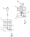
- the color changer shown schematically in Fig. 1 can known structure as a valve block 1 with any string Modules to form a housing with a straight central color channel 2 and in each case in rows along the color channel valve bodies distributed on opposite sides if necessary to have.
- the valve body contains 2 connected to the paint channel for example pneumatically controllable valves, of which a flushing agent valve V1 for the controlled introduction of at V as Detergent supplied thinner in the color changer, a pulse air valve PL1 for the controlled introduction of compressed air, various Color valves F1, F2, F3 and Fn for introducing coating material F of the selected color and a bleed valve RF2 are highlighted.
- the remaining valve positions are of no importance for the explanation of the invention.
- Color pressure regulator FDR arranged, of which a line 4 via a Dosing device, e.g. B. a metering pump 5 to an atomizer or other application organ Z leads with the usual Return valve RF1 is equipped.
- the FDR color pressure regulator limits the outlet pressure to the pump.
- the metering pump 5, for example a gear pump, is via a flushing valve V3 flushable with thinner V and provided with a bypass valve BY.
- the pulse air valve is located according to FIG. 1 PL1 now at the output end of color channel 2, so that all Color valves F1 to Fn along the color channel 2 between the pulse air valve PL1 and the one at the opposite end of the color channel located detergent and vent valves V1 and RF2 are.
- the flushing agent valve V1 is opened, so that thinner liquid from the input end of the paint channel to its exit and through it to a (not shown) Diverter valve before or on the application member Z flows.
- the subsequent changing intervals of pulse air and thinner can for example be the same Time like the pulse air valve PL1 also the vent valve RF2 opened and thus fully exploited the dynamics of the pulse air become.
- the vent valve RF2 can then again before the Pulse air valve PL1 should be closed as it is advisable if the entire pulse air is briefly through the output 3 of the Color changer is forced.
- the color pressure regulator FDR can, however, also with the vent valve RF2 open one of the pressure conditions, i.e. the flow resistance of the Color pressure regulator FDR and the subsequent line system dependent part of the pulse air or the air-detergent mixture flow towards the application organ Z.
- the entire air / detergent mixture flows when valve RF2 is closed to this exit, and when opening the vent valve RF2 reverses all or part of its flow direction around, which results in an additional cleaning effect. Since the flow resistance towards the valve RF2 is essential is lower than through the color pressure regulator FDR in the direction to the application organ, the valve is open when the RF2 valve is open to the input end of the valve block 1 flowing volume flow accordingly larger than the negligible residual flow through output 3. But it is also possible to use the color pressure regulator Close FDR when opening valve RF2.
- the rinsing process required at short notice the direction of flow of a flushing medium can be reversed in whole or in part.
- the reversal does not require the closing of a shut-off device or in the considered example of output 3, but can by opening an additional outlet, here that of the vent valve RF2 and the changing pressure conditions can be achieved.
- the reversal of the flow direction leaves in principle also with the embodiment described here different arrangements of air and thinner valves to reach.
- the flushing time is considerable due to the invention reduced (from 9.2 s to 5.8 s).
- the required Reduced amount of detergent in the example examined from 283 g to 168 g, of which 265 g in the first case and in the second Fall 140 g on the return through the return valve RF1 on Application organ Z omitted).
- rinse programs are also conceivable in which the detergent at certain times during the cleaning process the bleeder valve of the color changer is led out.
- Fig. 2 The comparison shown in Fig. 2 was made without using the usual so-called EDPS flushing system, in which the flushing medium at a higher pressure than with standard flushing an injector is directed into the color changer and in interaction with the pulsed air an aerosol is created, with which especially is rinsed intensively and in a way that saves dishwashing medium
- EDPS flush but can also be useful in the case described here Color changers can be applied.
- the A certain amount of detergent per unit of time flow through the size of the opening and the pressure of the feed Detergent can be set. Through the exit of the detergent through the nozzle opening is also atomized of the detergent is reached, which reduces the cleaning effect is improved.
- the solvent can through the upstream, as a shut-off valve serving valve V1 are clocked or flow continuously.
- the color channel 2 can be selected from those explained in EP 0 979 964 A2 For the reasons described there, from the previously usual circular shape deviating elongated, e.g. B. approximately oval cross-section have, as shown in Fig. 4 at Q. In a further embodiment it is advantageous if the jet shape comes out of the nozzle D escaping detergent of the oval cross-sectional shape of the paint channel is adjusted. So it is a conical one Flat jet ST with a color channel cross-section Opening angle ⁇ and the length a and width b of the channel cross section Q corresponding dimensions.
- the arrangement and / or shape of the nozzle D described can also in the case of arrangements of the solvent and Pulse air valves can be advantageous, even with conventional color changers with the arrangement of these two valves at the same end of the Color channel.
Landscapes
- Spray Control Apparatus (AREA)
- Details Or Accessories Of Spraying Plant Or Apparatus (AREA)
- Nozzles (AREA)
- Automatic Analysis And Handling Materials Therefor (AREA)
- Multiple-Way Valves (AREA)
Applications Claiming Priority (2)
| Application Number | Priority Date | Filing Date | Title |
|---|---|---|---|
| DE19951956 | 1999-10-29 | ||
| DE19951956A DE19951956A1 (de) | 1999-10-29 | 1999-10-29 | Ventilanordnung und Verfahren zum Spülen eines Farbwechslers |
Publications (3)
| Publication Number | Publication Date |
|---|---|
| EP1095707A2 true EP1095707A2 (fr) | 2001-05-02 |
| EP1095707A3 EP1095707A3 (fr) | 2003-06-04 |
| EP1095707B1 EP1095707B1 (fr) | 2006-09-13 |
Family
ID=7927177
Family Applications (1)
| Application Number | Title | Priority Date | Filing Date |
|---|---|---|---|
| EP00123535A Expired - Lifetime EP1095707B1 (fr) | 1999-10-29 | 2000-10-27 | Ensemble de valves de changement de couleur et procédé de rinçage d'un dispositif de changement de couleur |
Country Status (4)
| Country | Link |
|---|---|
| EP (1) | EP1095707B1 (fr) |
| AT (1) | ATE339256T1 (fr) |
| DE (2) | DE19951956A1 (fr) |
| ES (1) | ES2270771T3 (fr) |
Cited By (5)
| Publication number | Priority date | Publication date | Assignee | Title |
|---|---|---|---|---|
| EP2184111A4 (fr) * | 2007-08-31 | 2011-08-10 | Toyota Motor Co Ltd | Dispositif de chargement de matériau de couchage |
| US20110262622A1 (en) * | 2008-10-24 | 2011-10-27 | Frank Herre | Coating device and associated coating method |
| US9254501B2 (en) | 2009-10-21 | 2016-02-09 | Toyota Jidosha Kabushiki Kaisha | Method of supplying paint to a paint cartridge |
| US11097291B2 (en) | 2016-01-14 | 2021-08-24 | Dürr Systems Ag | Perforated plate with increased hole spacing in one or both edge regions of a row of nozzles |
| US11529645B2 (en) | 2016-01-14 | 2022-12-20 | Dürr Systems Ag | Perforated plate with a reduced diameter in one or both edge regions of a row of nozzles |
Families Citing this family (8)
| Publication number | Priority date | Publication date | Assignee | Title |
|---|---|---|---|---|
| DE10056259A1 (de) | 2000-11-14 | 2002-05-23 | Duerr Systems Gmbh | Farbwechselventilanordnung und Verfahren zu ihrer Steuerung |
| DE10233404A1 (de) | 2002-07-23 | 2004-02-05 | Dürr Systems GmbH | Verfahren und Ventilanordnung zum Steuern des Farbwechsels in einer Beschichtungsanlage |
| DE10335358A1 (de) * | 2003-08-01 | 2005-03-10 | Duerr Systems Gmbh | Beschichtungsmittelwechsler |
| DE10338064A1 (de) * | 2003-08-19 | 2005-05-25 | Daimlerchrysler Ag | Verfahren zum Spülen von Farbventilen |
| DE102006058562A1 (de) | 2006-12-12 | 2008-08-14 | Dürr Systems GmbH | Beschichtungseinrichtung mit einer Dosiervorrichtung |
| WO2008071273A2 (fr) | 2006-12-12 | 2008-06-19 | Dürr Systems GmbH | Dispositif de revêtement équipé d'un dispositif de dosage |
| DE102007029195A1 (de) | 2007-06-25 | 2009-02-19 | Dürr Systems GmbH | Beschichtungseinrichtung mit einer Dosiervorrichtung |
| DE102018131496A1 (de) | 2018-12-10 | 2020-06-10 | Lübbers Anlagen- und Umwelttechnik GmbH | Hochdruckventil für eine Zerstäuberdüse und Verfahren zum Nachreinigen eines Hochdruckventils |
Citations (2)
| Publication number | Priority date | Publication date | Assignee | Title |
|---|---|---|---|---|
| DE3221326A1 (de) | 1982-06-05 | 1983-06-16 | Daimler-Benz Ag, 7000 Stuttgart | Anlage zum maschinellen farbspritzen von serienteilen |
| EP0979964A2 (fr) | 1998-08-12 | 2000-02-16 | Dürr Systems GmbH | Ensemble de soupapes pour la commande de l'écoulement du matériau dans une installation de revêtement |
Family Cites Families (1)
| Publication number | Priority date | Publication date | Assignee | Title |
|---|---|---|---|---|
| FR2619322B1 (fr) * | 1987-08-14 | 1989-12-29 | Sames Sa | Installation de projection de produit de revetement tel que par exemple une peinture hydrosoluble |
-
1999
- 1999-10-29 DE DE19951956A patent/DE19951956A1/de not_active Ceased
-
2000
- 2000-10-27 AT AT00123535T patent/ATE339256T1/de not_active IP Right Cessation
- 2000-10-27 ES ES00123535T patent/ES2270771T3/es not_active Expired - Lifetime
- 2000-10-27 DE DE50013459T patent/DE50013459D1/de not_active Expired - Lifetime
- 2000-10-27 EP EP00123535A patent/EP1095707B1/fr not_active Expired - Lifetime
Patent Citations (2)
| Publication number | Priority date | Publication date | Assignee | Title |
|---|---|---|---|---|
| DE3221326A1 (de) | 1982-06-05 | 1983-06-16 | Daimler-Benz Ag, 7000 Stuttgart | Anlage zum maschinellen farbspritzen von serienteilen |
| EP0979964A2 (fr) | 1998-08-12 | 2000-02-16 | Dürr Systems GmbH | Ensemble de soupapes pour la commande de l'écoulement du matériau dans une installation de revêtement |
Cited By (9)
| Publication number | Priority date | Publication date | Assignee | Title |
|---|---|---|---|---|
| EP2184111A4 (fr) * | 2007-08-31 | 2011-08-10 | Toyota Motor Co Ltd | Dispositif de chargement de matériau de couchage |
| US8016001B2 (en) | 2007-08-31 | 2011-09-13 | Toyota Jidosha Kabushiki Kaisha | Painting material charging device |
| US20110262622A1 (en) * | 2008-10-24 | 2011-10-27 | Frank Herre | Coating device and associated coating method |
| US10150304B2 (en) * | 2008-10-24 | 2018-12-11 | Duerr Systems, Gmbh | Coating device and associated coating method |
| US10814643B2 (en) | 2008-10-24 | 2020-10-27 | Dürr Systems Ag | Coating device and associated coating method |
| US11241889B2 (en) | 2008-10-24 | 2022-02-08 | Dürr Systems GmbH | Coating device and associated coating method |
| US9254501B2 (en) | 2009-10-21 | 2016-02-09 | Toyota Jidosha Kabushiki Kaisha | Method of supplying paint to a paint cartridge |
| US11097291B2 (en) | 2016-01-14 | 2021-08-24 | Dürr Systems Ag | Perforated plate with increased hole spacing in one or both edge regions of a row of nozzles |
| US11529645B2 (en) | 2016-01-14 | 2022-12-20 | Dürr Systems Ag | Perforated plate with a reduced diameter in one or both edge regions of a row of nozzles |
Also Published As
| Publication number | Publication date |
|---|---|
| EP1095707B1 (fr) | 2006-09-13 |
| DE50013459D1 (de) | 2006-10-26 |
| ES2270771T3 (es) | 2007-04-16 |
| EP1095707A3 (fr) | 2003-06-04 |
| ATE339256T1 (de) | 2006-10-15 |
| DE19951956A1 (de) | 2001-06-13 |
Similar Documents
| Publication | Publication Date | Title |
|---|---|---|
| EP0292778B1 (fr) | Procédé et installation de revêtement électrostatique avec un produit de revêtement conducteur | |
| EP2076336B1 (fr) | Dispositif d'alimentation en fluide pour une installation de pulvérisation | |
| EP1095707B1 (fr) | Ensemble de valves de changement de couleur et procédé de rinçage d'un dispositif de changement de couleur | |
| DE19728155A1 (de) | Verfahren und Vorrichtung zum Lackieren | |
| DE69719530T2 (de) | Sprühkopf sowie mit dem selben versehener sprühbalken | |
| DE2747707A1 (de) | Anlage zum farbspritzen von serienteilen wechselnder farbe | |
| DE102019130612A1 (de) | Zerstäuber und zugehöriges Betriebsverfahren | |
| WO2018141511A1 (fr) | Système d'application pour le revêtement d'éléments de construction et dispositif de revêtement | |
| DE3717929C2 (fr) | ||
| DE102004034270B4 (de) | Anlage zum Austragen fließfähiger Fluide, insbesondere von Farben und Lacken und Verfahren zum Betrieb der Anlage | |
| EP1502657B1 (fr) | Changeur de produits pour revêtir | |
| DE102006022570A1 (de) | Beschichtungseinrichtung und zugehöriges Betriebsverfahren | |
| EP0541745B1 (fr) | Dispositif de revetement par pulverisation | |
| EP0447883B1 (fr) | Dispositif et procédé pour mélanger au moins deux composants réactifs de matière plastique | |
| DE102019130920A1 (de) | Farbversorgungssystem für eine Beschichtungsanlage und zugehöriges Betriebsverfahren | |
| EP4021644B1 (fr) | Dispositif comprenant un applicateur muni d'un réservoir destiné à recevoir un fluide à appliquer et un poste de recharge | |
| EP0568910B1 (fr) | Procédé et dispositif de nettoyage d'une installation de revêtement | |
| DE3809473C2 (fr) | ||
| DE3312268A1 (de) | Farbumlaufanlage fuer eine lackieranlage | |
| DE9106610U1 (de) | Sprühbeschichtungsvorrichtung | |
| DE10149981A1 (de) | Düsenanordnung für eine Waschanlage für Fahrzeugscheiben sowie Waschanlage mit einer solchen Düsenanordnung | |
| DE10235102B4 (de) | Lackiereinrichtung mit einer molchbaren Ventileinrichtung | |
| EP1384518B1 (fr) | Procédé ainsi qu'ensemble de valves pour commander le changement de couleur dans une installation de revêtement | |
| EP0842706A2 (fr) | Installation de revêtement et procédé de commande de l'écoulement du matériau de revêtement dans cette installation | |
| DE29719535U1 (de) | Vielfarb-Lackiereinrichtung |
Legal Events
| Date | Code | Title | Description |
|---|---|---|---|
| PUAI | Public reference made under article 153(3) epc to a published international application that has entered the european phase |
Free format text: ORIGINAL CODE: 0009012 |
|
| AK | Designated contracting states |
Kind code of ref document: A2 Designated state(s): AT BE CH CY DE DK ES FI FR GB GR IE IT LI LU MC NL PT SE |
|
| AX | Request for extension of the european patent |
Free format text: AL;LT;LV;MK;RO;SI |
|
| PUAL | Search report despatched |
Free format text: ORIGINAL CODE: 0009013 |
|
| AK | Designated contracting states |
Designated state(s): AT BE CH CY DE DK ES FI FR GB GR IE IT LI LU MC NL PT SE |
|
| AX | Request for extension of the european patent |
Extension state: AL LT LV MK RO SI |
|
| 17P | Request for examination filed |
Effective date: 20031117 |
|
| AKX | Designation fees paid |
Designated state(s): AT BE CH CY DE DK ES FI FR GB GR IE IT LI LU MC NL PT SE |
|
| 17Q | First examination report despatched |
Effective date: 20050614 |
|
| GRAP | Despatch of communication of intention to grant a patent |
Free format text: ORIGINAL CODE: EPIDOSNIGR1 |
|
| GRAS | Grant fee paid |
Free format text: ORIGINAL CODE: EPIDOSNIGR3 |
|
| RAP1 | Party data changed (applicant data changed or rights of an application transferred) |
Owner name: DUERR SYSTEMS GMBH |
|
| GRAA | (expected) grant |
Free format text: ORIGINAL CODE: 0009210 |
|
| AK | Designated contracting states |
Kind code of ref document: B1 Designated state(s): AT BE CH CY DE DK ES FI FR GB GR IE IT LI LU MC NL PT SE |
|
| PG25 | Lapsed in a contracting state [announced via postgrant information from national office to epo] |
Ref country code: IT Free format text: LAPSE BECAUSE OF FAILURE TO SUBMIT A TRANSLATION OF THE DESCRIPTION OR TO PAY THE FEE WITHIN THE PRESCRIBED TIME-LIMIT;WARNING: LAPSES OF ITALIAN PATENTS WITH EFFECTIVE DATE BEFORE 2007 MAY HAVE OCCURRED AT ANY TIME BEFORE 2007. THE CORRECT EFFECTIVE DATE MAY BE DIFFERENT FROM THE ONE RECORDED. Effective date: 20060913 Ref country code: FI Free format text: LAPSE BECAUSE OF FAILURE TO SUBMIT A TRANSLATION OF THE DESCRIPTION OR TO PAY THE FEE WITHIN THE PRESCRIBED TIME-LIMIT Effective date: 20060913 Ref country code: IE Free format text: LAPSE BECAUSE OF FAILURE TO SUBMIT A TRANSLATION OF THE DESCRIPTION OR TO PAY THE FEE WITHIN THE PRESCRIBED TIME-LIMIT Effective date: 20060913 |
|
| REG | Reference to a national code |
Ref country code: GB Ref legal event code: FG4D Free format text: NOT ENGLISH |
|
| REG | Reference to a national code |
Ref country code: CH Ref legal event code: EP |
|
| REG | Reference to a national code |
Ref country code: IE Ref legal event code: FG4D Free format text: LANGUAGE OF EP DOCUMENT: GERMAN |
|
| REF | Corresponds to: |
Ref document number: 50013459 Country of ref document: DE Date of ref document: 20061026 Kind code of ref document: P |
|
| PG25 | Lapsed in a contracting state [announced via postgrant information from national office to epo] |
Ref country code: CH Free format text: LAPSE BECAUSE OF NON-PAYMENT OF DUE FEES Effective date: 20061031 Ref country code: LI Free format text: LAPSE BECAUSE OF NON-PAYMENT OF DUE FEES Effective date: 20061031 Ref country code: MC Free format text: LAPSE BECAUSE OF NON-PAYMENT OF DUE FEES Effective date: 20061031 |
|
| PG25 | Lapsed in a contracting state [announced via postgrant information from national office to epo] |
Ref country code: DK Free format text: LAPSE BECAUSE OF FAILURE TO SUBMIT A TRANSLATION OF THE DESCRIPTION OR TO PAY THE FEE WITHIN THE PRESCRIBED TIME-LIMIT Effective date: 20061213 |
|
| REG | Reference to a national code |
Ref country code: SE Ref legal event code: TRGR |
|
| PG25 | Lapsed in a contracting state [announced via postgrant information from national office to epo] |
Ref country code: PT Free format text: LAPSE BECAUSE OF FAILURE TO SUBMIT A TRANSLATION OF THE DESCRIPTION OR TO PAY THE FEE WITHIN THE PRESCRIBED TIME-LIMIT Effective date: 20070226 |
|
| ET | Fr: translation filed | ||
| REG | Reference to a national code |
Ref country code: ES Ref legal event code: FG2A Ref document number: 2270771 Country of ref document: ES Kind code of ref document: T3 |
|
| REG | Reference to a national code |
Ref country code: IE Ref legal event code: FD4D |
|
| REG | Reference to a national code |
Ref country code: CH Ref legal event code: PL |
|
| PLBE | No opposition filed within time limit |
Free format text: ORIGINAL CODE: 0009261 |
|
| STAA | Information on the status of an ep patent application or granted ep patent |
Free format text: STATUS: NO OPPOSITION FILED WITHIN TIME LIMIT |
|
| 26N | No opposition filed |
Effective date: 20070614 |
|
| PG25 | Lapsed in a contracting state [announced via postgrant information from national office to epo] |
Ref country code: AT Free format text: LAPSE BECAUSE OF NON-PAYMENT OF DUE FEES Effective date: 20061027 |
|
| PG25 | Lapsed in a contracting state [announced via postgrant information from national office to epo] |
Ref country code: GR Free format text: LAPSE BECAUSE OF FAILURE TO SUBMIT A TRANSLATION OF THE DESCRIPTION OR TO PAY THE FEE WITHIN THE PRESCRIBED TIME-LIMIT Effective date: 20061214 |
|
| PG25 | Lapsed in a contracting state [announced via postgrant information from national office to epo] |
Ref country code: LU Free format text: LAPSE BECAUSE OF NON-PAYMENT OF DUE FEES Effective date: 20061027 |
|
| PG25 | Lapsed in a contracting state [announced via postgrant information from national office to epo] |
Ref country code: CY Free format text: LAPSE BECAUSE OF FAILURE TO SUBMIT A TRANSLATION OF THE DESCRIPTION OR TO PAY THE FEE WITHIN THE PRESCRIBED TIME-LIMIT Effective date: 20060913 |
|
| REG | Reference to a national code |
Ref country code: FR Ref legal event code: PLFP Year of fee payment: 16 |
|
| REG | Reference to a national code |
Ref country code: DE Ref legal event code: R082 Ref document number: 50013459 Country of ref document: DE Representative=s name: V. BEZOLD & PARTNER PATENTANWAELTE - PARTG MBB, DE Ref country code: DE Ref legal event code: R081 Ref document number: 50013459 Country of ref document: DE Owner name: DUERR SYSTEMS AG, DE Free format text: FORMER OWNER: DUERR SYSTEMS GMBH, 74321 BIETIGHEIM-BISSINGEN, DE |
|
| REG | Reference to a national code |
Ref country code: FR Ref legal event code: PLFP Year of fee payment: 17 |
|
| REG | Reference to a national code |
Ref country code: DE Ref legal event code: R082 Ref document number: 50013459 Country of ref document: DE Representative=s name: V. BEZOLD & PARTNER PATENTANWAELTE - PARTG MBB, DE Ref country code: DE Ref legal event code: R081 Ref document number: 50013459 Country of ref document: DE Owner name: DUERR SYSTEMS AG, DE Free format text: FORMER OWNER: DUERR SYSTEMS AG, 74321 BIETIGHEIM-BISSINGEN, DE |
|
| REG | Reference to a national code |
Ref country code: FR Ref legal event code: PLFP Year of fee payment: 18 |
|
| REG | Reference to a national code |
Ref country code: FR Ref legal event code: PLFP Year of fee payment: 19 |
|
| PGFP | Annual fee paid to national office [announced via postgrant information from national office to epo] |
Ref country code: SE Payment date: 20191021 Year of fee payment: 20 Ref country code: NL Payment date: 20191021 Year of fee payment: 20 Ref country code: DE Payment date: 20191021 Year of fee payment: 20 |
|
| PGFP | Annual fee paid to national office [announced via postgrant information from national office to epo] |
Ref country code: BE Payment date: 20191021 Year of fee payment: 20 Ref country code: IT Payment date: 20191028 Year of fee payment: 20 Ref country code: ES Payment date: 20191122 Year of fee payment: 20 Ref country code: FR Payment date: 20191028 Year of fee payment: 20 |
|
| PGFP | Annual fee paid to national office [announced via postgrant information from national office to epo] |
Ref country code: GB Payment date: 20191021 Year of fee payment: 20 |
|
| REG | Reference to a national code |
Ref country code: DE Ref legal event code: R071 Ref document number: 50013459 Country of ref document: DE |
|
| REG | Reference to a national code |
Ref country code: NL Ref legal event code: MK Effective date: 20201026 |
|
| REG | Reference to a national code |
Ref country code: GB Ref legal event code: PE20 Expiry date: 20201026 |
|
| REG | Reference to a national code |
Ref country code: BE Ref legal event code: MK Effective date: 20201027 |
|
| PG25 | Lapsed in a contracting state [announced via postgrant information from national office to epo] |
Ref country code: GB Free format text: LAPSE BECAUSE OF EXPIRATION OF PROTECTION Effective date: 20201026 |
|
| REG | Reference to a national code |
Ref country code: ES Ref legal event code: FD2A Effective date: 20210205 |
|
| PG25 | Lapsed in a contracting state [announced via postgrant information from national office to epo] |
Ref country code: ES Free format text: LAPSE BECAUSE OF EXPIRATION OF PROTECTION Effective date: 20201028 |