EP1095738A2 - Vorrichtung zum Einspannen eines länglichen Elements zwischen zwei äusseren Elementen und Satz solcher Vorrichtungen - Google Patents
Vorrichtung zum Einspannen eines länglichen Elements zwischen zwei äusseren Elementen und Satz solcher Vorrichtungen Download PDFInfo
- Publication number
- EP1095738A2 EP1095738A2 EP00203445A EP00203445A EP1095738A2 EP 1095738 A2 EP1095738 A2 EP 1095738A2 EP 00203445 A EP00203445 A EP 00203445A EP 00203445 A EP00203445 A EP 00203445A EP 1095738 A2 EP1095738 A2 EP 1095738A2
- Authority
- EP
- European Patent Office
- Prior art keywords
- elongated member
- clamping
- contact
- board
- rod
- Prior art date
- Legal status (The legal status is an assumption and is not a legal conclusion. Google has not performed a legal analysis and makes no representation as to the accuracy of the status listed.)
- Withdrawn
Links
Images
Classifications
-
- B—PERFORMING OPERATIONS; TRANSPORTING
- B25—HAND TOOLS; PORTABLE POWER-DRIVEN TOOLS; MANIPULATORS
- B25B—TOOLS OR BENCH DEVICES NOT OTHERWISE PROVIDED FOR, FOR FASTENING, CONNECTING, DISENGAGING, OR HOLDING
- B25B5/00—Clamps
- B25B5/06—Arrangements for positively actuating jaws
- B25B5/10—Arrangements for positively actuating jaws using screws
-
- E—FIXED CONSTRUCTIONS
- E04—BUILDING
- E04F—FINISHING WORK ON BUILDINGS, e.g. STAIRS, FLOORS
- E04F21/00—Implements for finishing work on buildings
- E04F21/18—Implements for finishing work on buildings for setting wall or ceiling slabs or plates
- E04F21/1838—Implements for finishing work on buildings for setting wall or ceiling slabs or plates for setting a plurality of similar elements
-
- E—FIXED CONSTRUCTIONS
- E04—BUILDING
- E04F—FINISHING WORK ON BUILDINGS, e.g. STAIRS, FLOORS
- E04F21/00—Implements for finishing work on buildings
- E04F21/18—Implements for finishing work on buildings for setting wall or ceiling slabs or plates
- E04F21/1838—Implements for finishing work on buildings for setting wall or ceiling slabs or plates for setting a plurality of similar elements
- E04F21/1844—Implements for finishing work on buildings for setting wall or ceiling slabs or plates for setting a plurality of similar elements by applying them one by one
- E04F21/185—Temporary edge support brackets
-
- E—FIXED CONSTRUCTIONS
- E04—BUILDING
- E04F—FINISHING WORK ON BUILDINGS, e.g. STAIRS, FLOORS
- E04F21/00—Implements for finishing work on buildings
- E04F21/18—Implements for finishing work on buildings for setting wall or ceiling slabs or plates
- E04F21/1838—Implements for finishing work on buildings for setting wall or ceiling slabs or plates for setting a plurality of similar elements
- E04F21/1844—Implements for finishing work on buildings for setting wall or ceiling slabs or plates for setting a plurality of similar elements by applying them one by one
- E04F21/1855—Implements for finishing work on buildings for setting wall or ceiling slabs or plates for setting a plurality of similar elements by applying them one by one of elongated elements, e.g. sidings
Definitions
- the present invention relates to a device for clamping an elongated member, such as a board between two external members.
- an elongated wooden reference board is set up to provide a horizontal reference line when setting up the first row of tiles. The board is placed at a levelled position and secured to the wall by nailing or clamping it onto the wall by using wedges between the two associated other wall members on each side of the wall.
- nailing the board to the wall is not attractive in wet room conditions, since this may damage the wall and water vapour may occur behind the tiles causing rapid deterioration of the wall.
- a device for clamping an elongated member such as a board or the like between two external members by placing said device at the end of the elongated member, said device comprising a threaded rod with a handle at a first end and a contact member at a second end, said rod being adjustably fastened to a contact plate provided with an end flange for receiving the end of the elongated member.
- a hitherto unknown device for temporary positioning of a reference board between two fixed members, e.g. for starting tiling of a wall in a bathroom or the like, or for other building purposes where an aligned reference board or a supporting bar is advantageous in order to make sure the tiles, stucco or the like are aligned.
- the device for clamping may also be used for temporary retention of a window or door frame during mounting or for other purposes where an "expansion push" is needed.
- a device is achieved which is quick in use and which makes it possible to set up a reference board quickly whilst making it easy to adjust the board to a predetermined position, such as a horizontal or vertical position.
- the end flange is a bent end section of the contact plate.
- a simple contact plate may be produced.
- the contact member is a contact shoe fitted to the end of the threaded rod by a pivotal joint connection so that the rod may be rotated relative to the contact shoe.
- a screw device for clamping according to the invention may be adjusted whilst in contact with an associated exterior member, since the rod may still be rotated even though the contact shoe is in contact with the side wall or the like.
- the end flange is provided with retention means, such as small spikes.
- retention means such as small spikes.
- the device may be temporarily retained at the end of a board. By using small spikes, the devices may easily be removed again after use.
- the invention also relates to a set of devices of the above-mentioned kind, comprising two devices for mounting at each end of an elongated member, such as a board so that the contact members of each device for clamping are brought into contact with a first and second external member on each side of the elongated member for retention of the board in a predetermined position between these external members.
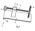
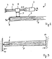
- Figures 1 and 2 show two embodiments of a device 1 for clamping according to the invention.
- the device 1 comprises a support plate 5 provided with an abutment flange 5a for receipt of the end of a board or the like at a first end.
- the flange 5a is provided by bending the end section of the support plate 5.
- the flange 5a and the support plate form a receiving section for the end of a reference board or the like.
- the flange may be provided with retention means 6, such as spikes for obtaining a firm grip on the board 9 (see fig. 2).
- a threaded rod 4 extends through the nut member 8 and engages the inside threading of the nut 8.
- the threaded rod 4 is preferably provided with a trapeze-threading.
- the rod 4 is provided with a handle 2 at the opposite end of the flange end and a pivotal contacting shoe 3 on the flange end of the device.
- the handle 2 may be provided in different shapes depending on the type of use, the size of the device, etc.
- the contact shoe 3 is connected to the threaded rod 4 via a universal joint, so that it may be freely rotatable and may pivot relative to the rod 4.
- the contact shoe extends beyond the end flange 5a for engagement with an exterior member 10, such a wall, see fig. 3.
- an exterior member 10 such a wall
- the board 9 placed in the receiving section of the support plate 5, i.e. abutting the support plate 5 and the end flange 5a may be clamped between two wall members 10 and thereby retained.
- one device according to the invention may preferably be used. However, if found appropriate two devices may also be used in order to gain an extra possibility for adjustment.
- a clamping effect may be obtained simply by expanding the device in the direction of the threaded rod 4.
- the rod 4 may preferably be provided with a self-locking thread in order to prevent the treaded connection (and thereby the clamping effect of the device) from slipping during use.
- the term board could be any kind elongated member.
- the elongated member preferably has a straight edge in its longitudinal direction.
Landscapes
- Engineering & Computer Science (AREA)
- Architecture (AREA)
- Mechanical Engineering (AREA)
- Civil Engineering (AREA)
- Structural Engineering (AREA)
- Finishing Walls (AREA)
Priority Applications (1)
| Application Number | Priority Date | Filing Date | Title |
|---|---|---|---|
| EP00203445A EP1095738A3 (de) | 1999-10-26 | 2000-10-05 | Vorrichtung zum Einspannen eines länglichen Elements zwischen zwei äusseren Elementen und Satz solcher Vorrichtungen |
Applications Claiming Priority (3)
| Application Number | Priority Date | Filing Date | Title |
|---|---|---|---|
| DK37199 | 1999-10-26 | ||
| DK199900371U DK199900371U3 (da) | 1999-10-26 | 1999-10-26 | Skruetvinge til påsætning i enden af et bræt |
| EP00203445A EP1095738A3 (de) | 1999-10-26 | 2000-10-05 | Vorrichtung zum Einspannen eines länglichen Elements zwischen zwei äusseren Elementen und Satz solcher Vorrichtungen |
Publications (2)
| Publication Number | Publication Date |
|---|---|
| EP1095738A2 true EP1095738A2 (de) | 2001-05-02 |
| EP1095738A3 EP1095738A3 (de) | 2003-03-12 |
Family
ID=26068439
Family Applications (1)
| Application Number | Title | Priority Date | Filing Date |
|---|---|---|---|
| EP00203445A Withdrawn EP1095738A3 (de) | 1999-10-26 | 2000-10-05 | Vorrichtung zum Einspannen eines länglichen Elements zwischen zwei äusseren Elementen und Satz solcher Vorrichtungen |
Country Status (1)
| Country | Link |
|---|---|
| EP (1) | EP1095738A3 (de) |
Cited By (3)
| Publication number | Priority date | Publication date | Assignee | Title |
|---|---|---|---|---|
| GB2499244A (en) * | 2012-02-10 | 2013-08-14 | Andrew Wright | Tiling support for window recess |
| CN111980376A (zh) * | 2020-08-31 | 2020-11-24 | 温州职业技术学院 | 一种建筑装修装置 |
| CN115110729A (zh) * | 2021-03-18 | 2022-09-27 | 广东博智林机器人有限公司 | 一种建筑材料铺贴基准装置及建筑材料铺贴机器人 |
Family Cites Families (5)
| Publication number | Priority date | Publication date | Assignee | Title |
|---|---|---|---|---|
| US5388813A (en) * | 1993-10-25 | 1995-02-14 | Arsenault; Cyrus L. | Ceiling clamp |
| DE4404310C2 (de) * | 1994-02-11 | 1999-03-04 | Bessey & Sohn | Spannwerkzeug |
| DE9417680U1 (de) * | 1994-11-10 | 1995-02-16 | Winkhold, Paul, 52159 Roetgen | Spannvorrichtung zum Verspannen von Platten (z.B. (z.B. Bodenplatten) |
| US5533709A (en) * | 1995-09-08 | 1996-07-09 | Tarbell; Russell | Woodworking press |
| DE29514833U1 (de) * | 1995-09-15 | 1995-11-16 | HEBRU-Gardinenland Brunnemer GmbH, 76879 Hochstadt | Vorrichtung zum Verlegen von Bodenbelägen |
-
2000
- 2000-10-05 EP EP00203445A patent/EP1095738A3/de not_active Withdrawn
Non-Patent Citations (1)
| Title |
|---|
| None |
Cited By (5)
| Publication number | Priority date | Publication date | Assignee | Title |
|---|---|---|---|---|
| GB2499244A (en) * | 2012-02-10 | 2013-08-14 | Andrew Wright | Tiling support for window recess |
| GB2499244B (en) * | 2012-02-10 | 2014-01-01 | Andrew Wright | Tiling support tool |
| CN111980376A (zh) * | 2020-08-31 | 2020-11-24 | 温州职业技术学院 | 一种建筑装修装置 |
| CN115110729A (zh) * | 2021-03-18 | 2022-09-27 | 广东博智林机器人有限公司 | 一种建筑材料铺贴基准装置及建筑材料铺贴机器人 |
| CN115110729B (zh) * | 2021-03-18 | 2024-03-22 | 广东博智林机器人有限公司 | 一种建筑材料铺贴基准装置及建筑材料铺贴机器人 |
Also Published As
| Publication number | Publication date |
|---|---|
| EP1095738A3 (de) | 2003-03-12 |
Similar Documents
| Publication | Publication Date | Title |
|---|---|---|
| US5205690A (en) | Concrete insert for attaching utility hangers to a structure | |
| US5111593A (en) | Template for positioning outlet boxes | |
| CA2144720A1 (en) | Bottom plate anchor for building frames | |
| JP3455539B2 (ja) | 支持要素 | |
| JPH02269267A (ja) | 上階コンクリートスラブ用の金属キー溝型枠に用いる調節自在な支持体 | |
| US5335470A (en) | Adjustable beam holder | |
| KR101666118B1 (ko) | 천장 마감 몰딩 | |
| US3779515A (en) | Adjustable decking and framing tool | |
| WO2004052151A1 (ja) | 棚受け金具 | |
| US20150218832A1 (en) | Frame hanger jig apparatus | |
| US6550152B2 (en) | Adjustable spirit level for tile and cabinet installation | |
| US6463710B1 (en) | Ledger bracket and method | |
| US6240702B1 (en) | Facia board rack | |
| US12139919B2 (en) | Tile niche holder tool, method, and system | |
| SK3698A3 (en) | Mounting for longitudinally grooved cover mouldings | |
| US3861111A (en) | Brick laying device | |
| EP1095738A3 (de) | Vorrichtung zum Einspannen eines länglichen Elements zwischen zwei äusseren Elementen und Satz solcher Vorrichtungen | |
| JPH08260658A (ja) | 二重壁支持材料 | |
| US20050102965A1 (en) | Device and method for correcting misalignment of building structural parts | |
| KR200389431Y1 (ko) | 바닥 콘크리트층의 수평레벨링장치 | |
| US7131643B1 (en) | Clamping system | |
| JPH0752226Y2 (ja) | 溝蓋受枠対の仮連結装置 | |
| KR950008947Y1 (ko) | 천정 판재 조립구 | |
| JP3090165U (ja) | 棚 | |
| KR970000177Y1 (ko) | 천정판 고정장치 |
Legal Events
| Date | Code | Title | Description |
|---|---|---|---|
| PUAI | Public reference made under article 153(3) epc to a published international application that has entered the european phase |
Free format text: ORIGINAL CODE: 0009012 |
|
| AK | Designated contracting states |
Kind code of ref document: A2 Designated state(s): AT BE CH CY DE DK ES FI FR GB GR IE IT LI LU MC NL PT SE |
|
| AX | Request for extension of the european patent |
Free format text: AL;LT;LV;MK;RO;SI |
|
| PUAL | Search report despatched |
Free format text: ORIGINAL CODE: 0009013 |
|
| AK | Designated contracting states |
Kind code of ref document: A3 Designated state(s): AT BE CH CY DE DK ES FI FR GB GR IE IT LI LU MC NL PT SE Designated state(s): AT BE CH CY DE DK ES FI FR GB GR IE IT LI LU MC NL PT SE |
|
| AX | Request for extension of the european patent |
Extension state: AL LT LV MK RO SI |
|
| RIC1 | Information provided on ipc code assigned before grant |
Ipc: 7E 04F 21/18 B Ipc: 7B 25B 5/10 A |
|
| AKX | Designation fees paid | ||
| REG | Reference to a national code |
Ref country code: DE Ref legal event code: 8566 |
|
| STAA | Information on the status of an ep patent application or granted ep patent |
Free format text: STATUS: THE APPLICATION IS DEEMED TO BE WITHDRAWN |
|
| 18D | Application deemed to be withdrawn |
Effective date: 20030913 |