EP1095891A2 - Vorrichtung und Verfahren zur Antrieb und Steuerung des Fadenzuführungsrohrs in Schussfadenliefervorrichtungen für Webmaschinen - Google Patents
Vorrichtung und Verfahren zur Antrieb und Steuerung des Fadenzuführungsrohrs in Schussfadenliefervorrichtungen für Webmaschinen Download PDFInfo
- Publication number
- EP1095891A2 EP1095891A2 EP00120199A EP00120199A EP1095891A2 EP 1095891 A2 EP1095891 A2 EP 1095891A2 EP 00120199 A EP00120199 A EP 00120199A EP 00120199 A EP00120199 A EP 00120199A EP 1095891 A2 EP1095891 A2 EP 1095891A2
- Authority
- EP
- European Patent Office
- Prior art keywords
- phase
- motor
- loop
- weft
- datum
- Prior art date
- Legal status (The legal status is an assumption and is not a legal conclusion. Google has not performed a legal analysis and makes no representation as to the accuracy of the status listed.)
- Granted
Links
- 238000004804 winding Methods 0.000 title claims abstract description 27
- 238000009941 weaving Methods 0.000 title claims abstract description 7
- 238000000034 method Methods 0.000 title claims description 18
- 230000004907 flux Effects 0.000 claims description 13
- 230000001276 controlling effect Effects 0.000 claims description 12
- 230000000875 corresponding effect Effects 0.000 claims description 6
- 238000012937 correction Methods 0.000 claims description 3
- 238000005259 measurement Methods 0.000 claims description 3
- 230000002596 correlated effect Effects 0.000 claims description 2
- 238000011156 evaluation Methods 0.000 claims 1
- 238000010586 diagram Methods 0.000 description 4
- 230000001133 acceleration Effects 0.000 description 3
- 238000012545 processing Methods 0.000 description 3
- 238000003780 insertion Methods 0.000 description 2
- 230000037431 insertion Effects 0.000 description 2
- 101100243943 Caenorhabditis elegans pid-5 gene Proteins 0.000 description 1
- 230000003247 decreasing effect Effects 0.000 description 1
- 230000001419 dependent effect Effects 0.000 description 1
- 238000005516 engineering process Methods 0.000 description 1
- 239000000284 extract Substances 0.000 description 1
- 230000000670 limiting effect Effects 0.000 description 1
- 238000012423 maintenance Methods 0.000 description 1
- 238000004519 manufacturing process Methods 0.000 description 1
- 238000013021 overheating Methods 0.000 description 1
- 230000000737 periodic effect Effects 0.000 description 1
- 230000002093 peripheral effect Effects 0.000 description 1
- 230000010363 phase shift Effects 0.000 description 1
- 239000004065 semiconductor Substances 0.000 description 1
Images


Classifications
-
- D—TEXTILES; PAPER
- D03—WEAVING
- D03D—WOVEN FABRICS; METHODS OF WEAVING; LOOMS
- D03D47/00—Looms in which bulk supply of weft does not pass through shed, e.g. shuttleless looms, gripper shuttle looms, dummy shuttle looms
- D03D47/34—Handling the weft between bulk storage and weft-inserting means
- D03D47/36—Measuring and cutting the weft
- D03D47/361—Drum-type weft feeding devices
- D03D47/367—Monitoring yarn quantity on the drum
-
- H—ELECTRICITY
- H02—GENERATION; CONVERSION OR DISTRIBUTION OF ELECTRIC POWER
- H02P—CONTROL OR REGULATION OF ELECTRIC MOTORS, ELECTRIC GENERATORS OR DYNAMO-ELECTRIC CONVERTERS; CONTROLLING TRANSFORMERS, REACTORS OR CHOKE COILS
- H02P25/00—Arrangements or methods for the control of AC motors characterised by the kind of AC motor or by structural details
- H02P25/02—Arrangements or methods for the control of AC motors characterised by the kind of AC motor or by structural details characterised by the kind of motor
- H02P25/08—Reluctance motors
Definitions
- the present invention relates to a device and a method for controlling the weft winding arm in weft feeders for weaving looms.
- Conventional weft feeders are devices which comprise a fixed drum on which a weft winding arm, which rotates around the drum, winds in a fishing-reel fashion a plurality of turns of yarn which constitute a weft reserve.
- the turns unwind from the drum of the feeder, when requested by the loom, at each weft insertion, and the weft winding arm, under the control of a supervisor microprocessor, rewinds the turns in order to restore the weft reserve.
- the motor most widely used for the movement of the weft winding arm is of the asynchronous three-phase type. This choice is essentially dictated by the inherent characteristics of these motors and mainly by their low manufacturing and maintenance costs, which are allowed by their simple and sturdy structure and by the complete lack of elements in mutual sliding contact.
- the main drawback is the impossibility to achieve simple and effective control of the torque delivered by the motor. To do this, it is in fact necessary to resort to sophisticated control systems of the vector type which however, due to their complexity and to their high computing power requirements, are not adapted to be installed at low cost in weft feeders. Accordingly, it is necessary to renounce to these expensive and complicated control systems and to assume an open-loop system for the adjustment of the speed of the motor, i.e. the synchronization speed set by the inverter is chased by the motor.
- the current absorbed by the motor is often significantly higher than the current that is actually necessary; accordingly, the power absorbed in excess is dissipated as heat, and this causes harmful overheating of the motor and of the electronic components of the power section of the inverter.
- the aim of the present invention is essentially to eliminate these severe drawbacks, and within the scope of this general aim the invention has the following particular objects:
- the present invention relates to a method and a device for controlling the rotation of the weft winding arm of a weft feeder, having the specific characteristics stated in the appended claims.
- a movement and control device in which the weft winding arm is moved by a switched-reluctance electric motor, whose speed is controlled by a first closed-loop adjustment system.
- the first system comprises a logic block which, by processing the pulsed signals of a first sensor or group of sensors for detecting the speed of the arm and of a second sensor or group of sensors for detecting the passage of the turns of weft that unwind from the feeder, obtains a datum which represents the reference variable of the feedback loop, the reference variable corresponding to the rotation rate that the winding arm must assume in order to correctly restore the weft turns.
- a second system also of the closed-loop type, is provided in order to control the torque delivered by the reluctance motor and is substantially adapted to adjust the value of the current circulating in the phase that is active and switched at the instant being considered, the torque being proportional to the square of the phase current.
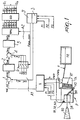
- Figure 1 illustrates a weft feeder P comprising a weft winding arm BR which, by rotating about the fixed drum TA of the feeder P, winds onto the drum a plurality of turns of yarn F which constitute a weft reserve RT.
- the yarn F which unwinds from a spool RO, passes through the cavity of the shaft of a motor which moves the arm BR, which is hollow as well, so that it is wound onto the drum TA, from which it unwinds, when requested by the loom TE, at each weft insertion.
- the motor for moving the arm BR is of the type commonly known as switched reluctance, designated by the reference sign SR, and is controlled by a pair of closed-loop systems which are generally designated by A1-A2 and are meant to ensure the correct operation of the weft winding arm both in terms of rotation rate and of acceleration or deceleration, in order to ensure the correct replenishment of the turns of the weft reserve RT as such turns unwind from the drum TA.
- the first loop A1 for controlling the rotation rate of the motor SR comprises a logic block R which receives pulsed signals P1-P2-P3 produced by sensors for detecting the angular position of the rotor of the motor SR, designated by S1-S2-S3, described hereinafter, and the pulsed signal produced by a sensor UWS, typically of the photocell type, which generates a signal peak UWP upon the passage of each turn that unwinds from the drum TA.
- the block R by processing signals P1-P2-P3 and UWP, extracts a signal, or more properly a datum, vel-ref which corresponds to the exact rate at which the arm BR must rotate in order to operate correctly.
- the datum vel-ref is the reference variable of the adjustment loop A1, whose measured variable, termed vel-mis, is the actual winding rate deduced by a logic block 3 which processes, for example, the time interval between two consecutive sets of three signals P1-P2-P3.
- the datum vel-mis is subtracted from the datum vel-ref in order to obtain an error datum "error" which is sent to a known PID regulator, designated by the reference numeral 2, which provides a datum Iref in terms of current which represents the torque/current reference of the second current adjustment loop A2.
- the second loop preset to control the current in the switched active phase of the motor SR, includes a block 3' associated with the block 3 and which also processes the pulsed signals P1-P2-P3 in order to provide a datum Fase-com which indicates, on the basis of the variations of the phase inductances L1-L2-L3 dependent on the mechanical angle ⁇ of the rotor, as more clearly described hereinafter, which of the three (or more) phases of the motor SR is to be energized at the instant being considered.
- the datum Fase-com is sent to a multiplexer 6 which, depending on said datum, chooses among the currents measured on the three (or more) phases which one to use to define the measured variable Imis of the second loop A2 for controlling the current that circulates in the switched phase of the motor.
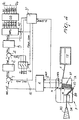
- the currents I1-I2-I3 circulating in the phases of the motor RS are obtained by amplifying, by means of respective amplifiers OP1, OP2, OP3 ( Figure 1a), the voltage drop across corresponding shunt resistors RS1-RS2-RS3 which are interposed between the ground (negative) and the respective power transistor Q2-Q4-Q6 of the inverter bridge PO.
- the difference Iref-Imis provides the error datum Ierr, which is applied to the input of a second PID regulator, designated by the reference numeral 5, for compensating the error Ierr.
- the PID 5 provides in output a numeric datum DUTY which can vary from 0 to 100 and represents the percentage of voltage, relative to the DC voltage V that supplies the inverter bridge PO, to be applied to the switched phase of the motor SR.
- a block WFG modulates the voltage signal on the phase to be energized at the instant being considered, providing corresponding pulse width modulation (PWM) pulses on its outputs GL1...GL6, while a subsequent gate driver block GD shifts the level of said pulses PWM to values which are present on its outputs G1-G6 and are adapted to drive the power transistors (MOSFETs) Q1-Q6 of the inverter bridge PO.
- PWM pulse width modulation
- the arrangement of the sensors depends on the number of stator poles and rotor poles of the motor SR, and is determined so as to achieve switching from one phase to the other when the rotor of the motor, as better explained hereinafter, is in the angular position corresponding to the beginning of the (positive or negative) variation of the inductance L of the phase to be switched; said inductance being variable ( Figure 3) according to the variation of the mutual position of the teeth of the stator poles and the teeth of the rotor poles.
- Figure 2 illustrates the relative angular arrangement of the three sensors S1-S2-S3 for decoding the rotor angle of a three-phase motor of the 6/4 type, i.e. a motor with six stator poles and four rotor poles.
- each sensor since four electrical periods are required in order to produce a complete rotation of the rotor, each sensor must provide a periodic signal with a period equal to 90 mechanical degrees of the rotor.
- the sensors are rigidly coupled to the outside of a disk DT (which lies outside the cylindrical portion M of the motor SR but is keyed on the shaft AM of the motor), which has four identical recessed notches TC, evenly spaced, and cover an angle of 45° each.
- the three signals P1-P2-P3 of the sensors S1-S2-S3 must have a mutual phase shift of 1/3 of an electric turn, i.e. 30 mechanical degrees, so that they are angularly spaced by 30° from each other.
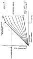
- Figure 3 plots, as mentioned, the progress of the inductances L1-L2-L3 of the three phases and the positioning of the signals P1-P2-P3 in relation to such inductances according to the mechanical angle ⁇ of the rotor of the motor.
- the chart related to the inductance L1 highlights the points AL of maximum alignment of the generic rotor pole with the stator pole of the first phase, which coincide with the maximum value of the inductance L1, and the points Na of maximum non-alignment of the poles, which coincide with the minimum value of the inductance of the phase.
- the motor SR is required to deliver a positive torque, e.g. in order to accelerate the well winding arm BR, the switching of each phase, for example the phase I already considered, begins at the points NA and ends at the points AL, the torque being a function (mathematical derivative) of the positive variation of the phase inductance L1.
- the motor is required to provide a braking torque, e.g. in order to slow the arm BR, the switching of each phase begins in the points AL and ends in the points NA; the braking or negative torque being a function of the negative variation of the inductance L1.
- the sensors S1-S2-S3 can be of any conventional type and are typically constituted by photocells or magnetic Hall sensors cooperating with a strip of permanent magnet (not shown) which is arranged outside the cylindrical portion M of the motor SR.
- This function by allowing to know the angle ⁇ of the rotor for a given value of the calculated flux ⁇ t and of the measured current I, allows to choose autonomously, i.e. independently of angular decoding signals of the rotor, the instant of switching from one phase to the other.
- a drawback of this switching method which however is advantageous thanks to the simplifications that it allows to introduce in the adjustment system of the loop A2, is the high uncertainty of the value ⁇ t calculated with (1). This is essentially due to the variability of the phase resistance R which, due to the thermal variations produced as the electrical load on the stator varies, can assume incorrect values which differ by 50-60% with respect to the nominal value.
- the phase voltage v also is easily subject to measurement errors and moreover is fully independent of the percentage of voltage across the power elements Q1-Q2 of the inverter bridge PO.
- the signal WSP is used to compensate both the errors in measurement of the phase voltage and the altered values assumed by the phase resistance R due to thermal drift.
Landscapes
- Engineering & Computer Science (AREA)
- Textile Engineering (AREA)
- Power Engineering (AREA)
- Looms (AREA)
- Control Of Electric Motors In General (AREA)
- Control Of Motors That Do Not Use Commutators (AREA)
Applications Claiming Priority (2)
| Application Number | Priority Date | Filing Date | Title |
|---|---|---|---|
| ITTO990928 | 1999-10-26 | ||
| IT1999TO000928A IT1311256B1 (it) | 1999-10-26 | 1999-10-26 | Dispositivo e metodo di movimentazione e controllo del braccioavvolgitrama negli apparecchi alimentatori di trama per telai di |
Publications (3)
| Publication Number | Publication Date |
|---|---|
| EP1095891A2 true EP1095891A2 (de) | 2001-05-02 |
| EP1095891A3 EP1095891A3 (de) | 2002-04-17 |
| EP1095891B1 EP1095891B1 (de) | 2004-02-18 |
Family
ID=11418173
Family Applications (1)
| Application Number | Title | Priority Date | Filing Date |
|---|---|---|---|
| EP00120199A Expired - Lifetime EP1095891B1 (de) | 1999-10-26 | 2000-09-25 | Vorrichtung und Verfahren zur Antrieb und Steuerung des Fadenzuführungsrohrs in Schussfadenliefervorrichtungen für Webmaschinen |
Country Status (5)
| Country | Link |
|---|---|
| US (1) | US6269844B1 (de) |
| EP (1) | EP1095891B1 (de) |
| CN (1) | CN1258013C (de) |
| DE (1) | DE60008337T2 (de) |
| IT (1) | IT1311256B1 (de) |
Families Citing this family (15)
| Publication number | Priority date | Publication date | Assignee | Title |
|---|---|---|---|---|
| US6948530B2 (en) * | 2004-01-02 | 2005-09-27 | Yi-Shan Yao | Weaving machine |
| ITTO20050256A1 (it) * | 2005-04-15 | 2006-10-16 | Lgl Electronics Spa | Alimentatore negativo di filato per macchine tessili e simili |
| ITTO20050469A1 (it) * | 2005-07-07 | 2007-01-08 | L G L Elecrtronics S P A | Dispositivo di recupero del filato per macchine tessili |
| ITTO20050484A1 (it) * | 2005-07-14 | 2007-01-15 | L G L Electronics Spa | Unita' di controllo per dispositivi di frenatura del filato in alimentatori di trama per telai di tessitura, e procedura di sintonizzazione della stessa |
| DE102005052693A1 (de) * | 2005-10-28 | 2007-05-03 | Wilhelm Stahlecker Gmbh | Antrieb einer Vorrichtung zur Herstellung von Maschenware |
| US7598683B1 (en) | 2007-07-31 | 2009-10-06 | Lsi Industries, Inc. | Control of light intensity using pulses of a fixed duration and frequency |
| US8604709B2 (en) | 2007-07-31 | 2013-12-10 | Lsi Industries, Inc. | Methods and systems for controlling electrical power to DC loads |
| US8903577B2 (en) | 2009-10-30 | 2014-12-02 | Lsi Industries, Inc. | Traction system for electrically powered vehicles |
| JP5095316B2 (ja) * | 2007-09-05 | 2012-12-12 | 東芝機械株式会社 | 織機及び織機の駆動装置。 |
| EP2169099A1 (de) * | 2008-09-25 | 2010-03-31 | L.G.L. Electronics S.p.A. | Negativer Garnzuführer mit Schussfadenbremsvorrichtung |
| CN103422233B (zh) * | 2012-05-16 | 2015-01-28 | 苏州御能动力科技有限公司 | 一种定长储纬器控制系统及采用该控制系统的控制方法 |
| DE102014019636A1 (de) * | 2014-06-06 | 2015-12-10 | Taiwan Semiconductor Mfg. Co., Ltd. | Regelkreis und Verfahren zum Betreiben eines solchen Regelkreises |
| IT202100017966A1 (it) * | 2021-07-08 | 2023-01-08 | Lgl Electronics Spa | Alimentatore di filato positivo motorizzato con modalità operativa selezionabile, ed apparato di alimentazione di filato utilizzante lo stesso. |
| CN114836896B (zh) * | 2022-04-19 | 2023-03-28 | 南京航空航天大学 | 一种异型截面壳体预制体三维编织的芯模引离方法及装置 |
| KR102972345B1 (ko) * | 2023-03-07 | 2026-06-04 | 지엘테크텍 주식회사 | 레피어 직기에서의 다중위사 위입장치 |
Citations (2)
| Publication number | Priority date | Publication date | Assignee | Title |
|---|---|---|---|---|
| EP0756373A1 (de) | 1995-07-25 | 1997-01-29 | Switched Reluctance Drives Limited | Regelung einer geschalteten Reluktanzmaschine |
| EP0802270A2 (de) | 1996-04-19 | 1997-10-22 | Switched Reluctance Drives Limited | Webmaschine |
Family Cites Families (6)
| Publication number | Priority date | Publication date | Assignee | Title |
|---|---|---|---|---|
| CH616902A5 (de) * | 1976-10-28 | 1980-04-30 | Sulzer Ag | |
| IT1135172B (it) * | 1981-01-26 | 1986-08-20 | Roy Electrotex Spa | Dispositivo elettrico di azionamento di apparecchi alimentatori di filo per macchine tessili |
| JPH07858B2 (ja) * | 1985-02-21 | 1995-01-11 | 株式会社豊田中央研究所 | ジエツトル−ムにおける複数のよこ糸選択貯留装置の制御装置 |
| JPS6292785A (ja) * | 1985-10-17 | 1987-04-28 | Brother Ind Ltd | ミシン駆動装置 |
| US5016680A (en) * | 1989-03-03 | 1991-05-21 | Kabushiki Kaisha Toyoda Jidoshokki Seisakusho | Weft processing and releasing apparatus in a jet loom |
| US5168202A (en) * | 1991-08-30 | 1992-12-01 | Platt Saco Lowell Corporation | Microprocessor control of electric motors |
-
1999
- 1999-10-26 IT IT1999TO000928A patent/IT1311256B1/it active
-
2000
- 2000-09-25 DE DE60008337T patent/DE60008337T2/de not_active Expired - Lifetime
- 2000-09-25 EP EP00120199A patent/EP1095891B1/de not_active Expired - Lifetime
- 2000-09-25 US US09/668,457 patent/US6269844B1/en not_active Expired - Lifetime
- 2000-10-26 CN CN00133005.5A patent/CN1258013C/zh not_active Expired - Fee Related
Patent Citations (2)
| Publication number | Priority date | Publication date | Assignee | Title |
|---|---|---|---|---|
| EP0756373A1 (de) | 1995-07-25 | 1997-01-29 | Switched Reluctance Drives Limited | Regelung einer geschalteten Reluktanzmaschine |
| EP0802270A2 (de) | 1996-04-19 | 1997-10-22 | Switched Reluctance Drives Limited | Webmaschine |
Also Published As
| Publication number | Publication date |
|---|---|
| EP1095891A3 (de) | 2002-04-17 |
| CN1294209A (zh) | 2001-05-09 |
| IT1311256B1 (it) | 2002-03-04 |
| DE60008337T2 (de) | 2004-12-09 |
| US6269844B1 (en) | 2001-08-07 |
| DE60008337D1 (de) | 2004-03-25 |
| EP1095891B1 (de) | 2004-02-18 |
| ITTO990928A0 (it) | 1999-10-26 |
| ITTO990928A1 (it) | 2001-04-26 |
| CN1258013C (zh) | 2006-05-31 |
Similar Documents
| Publication | Publication Date | Title |
|---|---|---|
| EP1095891B1 (de) | Vorrichtung und Verfahren zur Antrieb und Steuerung des Fadenzuführungsrohrs in Schussfadenliefervorrichtungen für Webmaschinen | |
| US10439525B2 (en) | Motor drive device and method for driving motor | |
| CA2171107C (en) | Pulse width modulating motor controller | |
| EP0285637B1 (de) | Motorerregungsschaltung | |
| EP0276625B1 (de) | Steuergerät und Methode zur Steurerung eines Schrittschaltreluktanzmotors | |
| EP0780966B1 (de) | Sensorlose Rotorlageüberwachung in einer Reluktanzmaschine | |
| US8970146B2 (en) | Controller for electrical machines | |
| US6570351B2 (en) | Sensorless motor driving apparatus | |
| EP3665770B1 (de) | Verfahren und system zur steuerung einer geschalteten reluktanzmaschine | |
| JP5403765B2 (ja) | 電気機械の制御 | |
| EP3825132B1 (de) | Drucker | |
| US6356048B1 (en) | Method and device for controlling electric motors of the brushless direct-current type, particularly for moving the weft winding arm in weft feeders for weaving looms | |
| US20030137273A1 (en) | Method and apparatus for controlling acceleration and velocity of a stepper motor | |
| CN109874390B (zh) | 具有无刷dc马达的线性致动器 | |
| GB2581250A (en) | Position corrected commutation of brushless direct current motors | |
| JP3906429B2 (ja) | 同期モータの駆動装置 | |
| GB2305022A (en) | Starting a single phase reluctance motor | |
| JP2004520793A (ja) | ブラシレスモータの制御システム | |
| EP2053736A2 (de) | Steuerverfahren für positive Garnzuführer | |
| WO2016067051A1 (en) | Tape drive and transfer printer | |
| US20020113566A1 (en) | Method and actuation control for stopping an electrical drive, by means of closed-loop position control, in a predetermined nominal position | |
| US20140239862A1 (en) | Control of a brushless electrical machine | |
| JP3992085B2 (ja) | ブラシレスモータ駆動制御装置 | |
| JP4144023B2 (ja) | ステッピングモータ制御装置 | |
| JP3362686B2 (ja) | モータ制御装置 |
Legal Events
| Date | Code | Title | Description |
|---|---|---|---|
| PUAI | Public reference made under article 153(3) epc to a published international application that has entered the european phase |
Free format text: ORIGINAL CODE: 0009012 |
|
| AK | Designated contracting states |
Kind code of ref document: A2 Designated state(s): AT BE CH CY DE DK ES FI FR GB GR IE IT LI LU MC NL PT SE Kind code of ref document: A2 Designated state(s): BE CH DE LI SE |
|
| AX | Request for extension of the european patent |
Free format text: AL;LT;LV;MK;RO;SI |
|
| PUAL | Search report despatched |
Free format text: ORIGINAL CODE: 0009013 |
|
| AK | Designated contracting states |
Kind code of ref document: A3 Designated state(s): AT BE CH CY DE DK ES FI FR GB GR IE IT LI LU MC NL PT SE |
|
| AX | Request for extension of the european patent |
Free format text: AL;LT;LV;MK;RO;SI |
|
| RIC1 | Information provided on ipc code assigned before grant |
Free format text: 7B 65H 51/22 A, 7H 02P 5/05 B |
|
| TPAD | Observations by third parties |
Free format text: ORIGINAL CODE: EPIDOS TIPA |
|
| 17P | Request for examination filed |
Effective date: 20020927 |
|
| AKX | Designation fees paid |
Free format text: BE CH DE LI SE |
|
| GRAP | Despatch of communication of intention to grant a patent |
Free format text: ORIGINAL CODE: EPIDOSNIGR1 |
|
| GRAS | Grant fee paid |
Free format text: ORIGINAL CODE: EPIDOSNIGR3 |
|
| GRAA | (expected) grant |
Free format text: ORIGINAL CODE: 0009210 |
|
| AK | Designated contracting states |
Kind code of ref document: B1 Designated state(s): BE CH DE LI SE |
|
| REG | Reference to a national code |
Ref country code: SE Ref legal event code: TRGR |
|
| REG | Reference to a national code |
Ref country code: CH Ref legal event code: NV Representative=s name: ROTTMANN, ZIMMERMANN + PARTNER AG Ref country code: CH Ref legal event code: EP |
|
| REG | Reference to a national code |
Ref country code: IE Ref legal event code: FG4D |
|
| REF | Corresponds to: |
Ref document number: 60008337 Country of ref document: DE Date of ref document: 20040325 Kind code of ref document: P |
|
| PLBE | No opposition filed within time limit |
Free format text: ORIGINAL CODE: 0009261 |
|
| STAA | Information on the status of an ep patent application or granted ep patent |
Free format text: STATUS: NO OPPOSITION FILED WITHIN TIME LIMIT |
|
| 26N | No opposition filed |
Effective date: 20041119 |
|
| REG | Reference to a national code |
Ref country code: IE Ref legal event code: MM4A |
|
| PGFP | Annual fee paid to national office [announced via postgrant information from national office to epo] |
Ref country code: CH Payment date: 20090826 Year of fee payment: 10 |
|
| REG | Reference to a national code |
Ref country code: CH Ref legal event code: PL |
|
| PG25 | Lapsed in a contracting state [announced via postgrant information from national office to epo] |
Ref country code: CH Free format text: LAPSE BECAUSE OF NON-PAYMENT OF DUE FEES Effective date: 20100930 Ref country code: LI Free format text: LAPSE BECAUSE OF NON-PAYMENT OF DUE FEES Effective date: 20100930 |
|
| PGFP | Annual fee paid to national office [announced via postgrant information from national office to epo] |
Ref country code: SE Payment date: 20160921 Year of fee payment: 17 |
|
| PGFP | Annual fee paid to national office [announced via postgrant information from national office to epo] |
Ref country code: BE Payment date: 20160921 Year of fee payment: 17 |
|
| PGFP | Annual fee paid to national office [announced via postgrant information from national office to epo] |
Ref country code: DE Payment date: 20170925 Year of fee payment: 18 |
|
| REG | Reference to a national code |
Ref country code: SE Ref legal event code: EUG |
|
| REG | Reference to a national code |
Ref country code: BE Ref legal event code: MM Effective date: 20170930 |
|
| PG25 | Lapsed in a contracting state [announced via postgrant information from national office to epo] |
Ref country code: BE Free format text: LAPSE BECAUSE OF NON-PAYMENT OF DUE FEES Effective date: 20170930 |
|
| REG | Reference to a national code |
Ref country code: DE Ref legal event code: R119 Ref document number: 60008337 Country of ref document: DE |
|
| PG25 | Lapsed in a contracting state [announced via postgrant information from national office to epo] |
Ref country code: DE Free format text: LAPSE BECAUSE OF NON-PAYMENT OF DUE FEES Effective date: 20190402 Ref country code: SE Free format text: LAPSE BECAUSE OF NON-PAYMENT OF DUE FEES Effective date: 20170926 |