EP1096115A1 - Mechanische Regelung der Hubverstellung des Einlassventils eines Verbrennungsmotors - Google Patents
Mechanische Regelung der Hubverstellung des Einlassventils eines Verbrennungsmotors Download PDFInfo
- Publication number
- EP1096115A1 EP1096115A1 EP99122662A EP99122662A EP1096115A1 EP 1096115 A1 EP1096115 A1 EP 1096115A1 EP 99122662 A EP99122662 A EP 99122662A EP 99122662 A EP99122662 A EP 99122662A EP 1096115 A1 EP1096115 A1 EP 1096115A1
- Authority
- EP
- European Patent Office
- Prior art keywords
- lifting lever
- valve
- internal combustion
- combustion engine
- camshaft
- Prior art date
- Legal status (The legal status is an assumption and is not a legal conclusion. Google has not performed a legal analysis and makes no representation as to the accuracy of the status listed.)
- Granted
Links
Images
Classifications
-
- F—MECHANICAL ENGINEERING; LIGHTING; HEATING; WEAPONS; BLASTING
- F01—MACHINES OR ENGINES IN GENERAL; ENGINE PLANTS IN GENERAL; STEAM ENGINES
- F01L—CYCLICALLY OPERATING VALVES FOR MACHINES OR ENGINES
- F01L13/00—Modifications of valve-gear to facilitate reversing, braking, starting, changing compression ratio, or other specific operations
- F01L13/0015—Modifications of valve-gear to facilitate reversing, braking, starting, changing compression ratio, or other specific operations for optimising engine performances by modifying valve lift according to various working parameters, e.g. rotational speed, load, torque
- F01L13/0021—Modifications of valve-gear to facilitate reversing, braking, starting, changing compression ratio, or other specific operations for optimising engine performances by modifying valve lift according to various working parameters, e.g. rotational speed, load, torque by modification of rocker arm ratio
- F01L13/0026—Modifications of valve-gear to facilitate reversing, braking, starting, changing compression ratio, or other specific operations for optimising engine performances by modifying valve lift according to various working parameters, e.g. rotational speed, load, torque by modification of rocker arm ratio by means of an eccentric
-
- F—MECHANICAL ENGINEERING; LIGHTING; HEATING; WEAPONS; BLASTING
- F01—MACHINES OR ENGINES IN GENERAL; ENGINE PLANTS IN GENERAL; STEAM ENGINES
- F01L—CYCLICALLY OPERATING VALVES FOR MACHINES OR ENGINES
- F01L2305/00—Valve arrangements comprising rollers
Definitions
- the present invention relates to a mechanically controllable valve lift adjustment.
- the present invention further relates to an internal combustion engine with a mechanical adjustable valve stroke adjustment and a method for regulating the valve strokes in internal combustion engines.
- a vacuum occurs when the load changes from full to partial load in the cylinders due to the more fuel than needed in the cylinders is sucked. This increases the fuel consumption of the internal combustion engine, and unburned fuel may leak into the environment.
- the object is therefore to provide a device with which the fuel consumption of an internal combustion engine can be reduced.
- valve lift adjustment according to the invention additionally a roller rocker arm, which on the one hand matches the working curve of the Lever cooperates and is driven by this and on the other hand with the valve cooperates and moves it.
- the valve lift adjustment has a means with which the lift lever is rotatable and slidably mounted in a backdrop. This is preferably Means a role.
- the backdrop takes up the means and thus represents its leadership, within which the means and with it the lifting lever moves under pressure and / or tension.
- the backdrop can have any shape that is chosen by the person skilled in the art that the lifting lever preferably along a certain straight line and / or curve is movable.
- the backdrop preferably has a substantially rectangular shape, whereby the short sides of the rectangle are preferably designed in the form of a semicircle are. This shape of the backdrop is particularly suitable for holding roles.
- This backdrop can be horizontal or vertical or at any angle Be arranged horizontally or vertically.
- the backdrop is also preferably in the form of a circular arc, the shape of which preferably by the geometry of the roller finger follower, in particular by the Role of the roller finger follower is defined.
- the backdrop is it e.g. possible to implement a so-called 0-stroke, in which the respective Valve remains completely closed.
- the shape of the backdrop is that of the respective one Valve is assigned, preferably different, whereby different Have the stroke characteristics realized per valve.
- the valve lift adjustment according to the invention has two means that interact with the lifting lever and this in the Move the backdrop or move it to a specific location in the backdrop for a fix certain time.
- One means is preferably an eccentric shaft, the other A means is preferably a return spring, the return spring being the lifting lever presses against the eccentric shaft and against the camshaft.
- the eccentric shaft is preferably driven by an electric motor, a stepper motor and / or driven by a worm or gear transmission.
- the central axis of the means that is associated with the Camshaft interacts on a horizontal plane with the central axis of the Camshaft.
- the means that cooperate with the camshaft is a roller.
- valve control according to the invention is suitable for valves of any kind.
- the valves are valves of internal combustion engines, particularly preferred Intake valves for internal combustion engines.
- Another object of the present invention therefore relates to an internal combustion engine, which has at least one valve control according to the invention.
- At least 4, particularly preferably 6, 8 or 12, are preferably according to the invention Valve controls are available in the internal combustion engine.
- the lifting levers are preferably rotatable mounted on a shaft, the ends of which are guided in scenes that are in the cylinder head are located.
- the cylinder head has a special bearing cap on.
- Another object of the present invention is a method for control of the stroke of an intake valve of an internal combustion engine using the Valve control according to the invention, in which the lifting lever corresponding to the Performance requirement for the internal combustion engine is shifted in the backdrop.
- the lifting lever is moved in this way and for a certain time Position held that the valve or the roller rocker arm with part of the Working curve of the lifting lever is in contact, which reduces the stroke of the valve causes.
- the lifting lever At full load, the lifting lever is moved in this way and for a certain time Position held that the valve or the roller rocker arm with part of the Working curve of the lifting lever is in contact with the maximum stroke of the valve causes.
- the present invention has the advantage that the valve lift depending on the performance requirement can be increased or decreased.
- Valve stroke adjustment reduces the gas exchange work in Otto engines and it This results in fuel savings of up to 10% compared to valve control according to the state of the art.
- the mechanical control is much easier and thus cheaper to produce than z.
- the valve control according to the invention is very robust and not maintenance-prone.
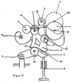
- a lever 1 is slidably mounted with the roller 2 in a setting 3 (only partially shown).
- the roller can also be a shaft on which each lifting lever is rotatably mounted.
- the lifting lever is moved by the eccentric shaft 5 and the return spring 5 in the backdrop.
- the direction in which the lifting lever is moved in the link is shown by line 14.
- the person skilled in the art understands that the lifting lever 1 can also be held in a certain position within the backdrop by the two means 5.
- the eccentric shaft is driven by a stepper motor (not shown).
- the lifting lever 1 has a further roller 9, which is connected to the camshaft 6 cooperates, and which drives the lifting lever 1.
- the lifting lever 1 has a working curve 4, which approximately has the shape of a parabola. This working curve is in contact with the roller 15, the is attached to the roller rocker arm 7. The roller rocker arm 7 in turn moves the valve 8.
- the central axis 13 of the roller 9 is below the Central axis 10 of the camshaft 6, or the central axis 13 of the roller 9 is as shown in dashed lines, in the same horizontal plane as the central axis 10 of the Camshaft 6 arranged.
Landscapes
- Engineering & Computer Science (AREA)
- Mechanical Engineering (AREA)
- General Engineering & Computer Science (AREA)
- Valve Device For Special Equipments (AREA)
Abstract
Description
- Einem Hubhebel, der
- ein Mittel, mit dem der Hubhebel drehbar und in einer Kulisse verschieblich gelagert ist,
- ein Mittel, das mit einer Nockenwelle, die den Hubhebel antreibt, zusammenwirkt und
- eine Arbeitskurve
- Mindestens einem Mittel, das mit dem Hubhebel zusammenwirkt und diesen in der Kulisse verschiebt,
- Einer Nockenwelle, die den Hubhebel antreibt,
- Einem Ventil, das mit der Arbeitskurve des Hubhebels zusammenwirkt und von diesem bewegt wird,
Claims (12)
- Mechanisch regelbare Ventilhubverstellung mit:Einem Hubhebel (1), deraufweist,ein Mittel (2), mit dem der Hubhebel (1) drehbar und in einer Kulisse (3) verschieblich gelagert ist,ein Mittel (9), das mit einer Nockenwelle (6), die den Hubhebel (1) antreibt, zusammenwirkt undeine Arbeitskurve (4)Mindestens einem Mittel (5), das mit dem Hubhebel (1) zusammenwirkt und diesen in der Kulisse verschiebt,Einer Nockenwelle (6), die mit dem Mittel (9) des Hubhebels (1) zusammenwirkt und diesen antreibt,Einem Ventil (8), das mit der Arbeitskurve (4) des Hubhebels (1) zusammenwirkt und von diesem bewegt wird.
- Mechanisch regelbare Ventilhubverstellung mit:Einem Hubhebel (1), deraufweist,ein Mittel (2), mit dem der Hubhebel (1) drehbar und in einer Kulisse (3) verschieblich gelagert ist,ein Mittel (9), das mit einer Nockenwelle (6), die den Hubhebel (1) antreibt, zusammenwirkt undeine Arbeitskurve (4)Mindestens einem Mittel (5), das mit dem Hubhebel (1) zusammenwirkt und diesen in der Kulisse verschiebt,Einer Nockenwelle (6), die mit dem Mittel (9) des Hubhebels (1) zusammenwirkt und diesen antreibt,Einem Rollenschlepphebel (7), der mit der Arbeitskurve (4) des Hubhebels (1) zusammenwirkt und von diesem angetrieben wird,Einem Ventil (8), das mit dem Rollenschlepphebel (7) zusammenwirkt und von diesem bewegt wird.
- Ventilhubverstellung nach Anspruch 1 oder 2, dadurch gekennzeichnet, daß sie zwei Mittel (5) aufweist, wobei ein Mittel eine Exzenterwelle und das andere Mittel vorzugsweise eine Rückstellfeder ist.
- Ventilhubverstellung nach Anspruch 3, dadurch gekennzeichnet, daß die Exzenterwelle durch einen E-Motor, Schrittmotor oder ein Schnecken- oder Zahnradgetriebe angetrieben wird.
- Ventilsteuerung nach einem der Ansprüche 1 bis 4, dadurch gekennzeichnet, daß die Mittelachse (13) des Mittels (9) auf derselben horizontalen Ebene angeordnet ist wie die Mittelachse (10) der Nockenwelle (6).
- Ventilsteuerung nach einem der Ansprüche 1 bis 4, dadurch gekennzeichnet, daß die Mittelachse (13) des Mittels (9) unterhalb der Mittelachse (10) der Nockenwelle (6) angeordnet ist.
- Ventilsteuerung nach einem der Ansprüche 1 bis 6, dadurch gekennzeichnet, daß das Mittel (2) und/oder das Mittel (9) eine Rolle ist.
- Ventilsteuerung nach einem der Ansprüche 1 bis 7, dadurch gekennzeichnet, daß das Ventil ein Einlaßventil eines Verbrennungsmotors ist.
- Verbrennungsmotor, dadurch gekennzeichnet, daß er mindestens 4, vorzugsweise 6, 8 oder 12 Ventilsteuerungen gemäß einem der Ansprüche 1 bis 8 aufweist.
- Verfahren zur Steuerung des Hubes eines Einlaßventiles eines Verbrennungsmotors unter Verwendung einer Ventilsteuerung nach einem der Ansprüche 1 bis 8, dadurch gekennzeichnet, daß der Hubhebel (1) entsprechend der Leistungsanforderung an den Verbrennungsmotor in der Kulisse (3) verschoben wird.
- Verfahren nach Anspruch 10, dadurch gekennzeichnet, daß bei Teillast des Verbrennungsmotors der Hubhebel (1) so verschoben wird, daß der linke Teil (11) der Arbeitskurve (4) mit dem Ventil oder dem Rollenschlepphebel (7) zusammenwirkt.
- Verfahren nach Anspruch 10, dadurch gekennzeichnet, daß bei Vollast des Verbrennungsmotors der Hubhebel (1) so verschoben wird, daß der rechte Teil (12) der Arbeitskurve (4) mit dem Ventil oder dem Rollenschlepphebel (7) zusammenwirkt.
Priority Applications (1)
| Application Number | Priority Date | Filing Date | Title |
|---|---|---|---|
| EP99122662A EP1096115B1 (de) | 1999-10-29 | 1999-11-15 | Mechanische Regelung der Hubverstellung des Einlassventils eines Verbrennungsmotors |
Applications Claiming Priority (3)
| Application Number | Priority Date | Filing Date | Title |
|---|---|---|---|
| EP99121609 | 1999-10-29 | ||
| EP99121609 | 1999-10-29 | ||
| EP99122662A EP1096115B1 (de) | 1999-10-29 | 1999-11-15 | Mechanische Regelung der Hubverstellung des Einlassventils eines Verbrennungsmotors |
Publications (2)
| Publication Number | Publication Date |
|---|---|
| EP1096115A1 true EP1096115A1 (de) | 2001-05-02 |
| EP1096115B1 EP1096115B1 (de) | 2002-07-10 |
Family
ID=26153159
Family Applications (1)
| Application Number | Title | Priority Date | Filing Date |
|---|---|---|---|
| EP99122662A Expired - Lifetime EP1096115B1 (de) | 1999-10-29 | 1999-11-15 | Mechanische Regelung der Hubverstellung des Einlassventils eines Verbrennungsmotors |
Country Status (1)
| Country | Link |
|---|---|
| EP (1) | EP1096115B1 (de) |
Cited By (12)
| Publication number | Priority date | Publication date | Assignee | Title |
|---|---|---|---|---|
| EP1255027A1 (de) * | 2001-05-03 | 2002-11-06 | STS System Technology Services GmbH | Mechanische Regelung der Hubverstellung des Einlassventils eines Verbrennungsmotors |
| WO2002092972A1 (de) * | 2001-05-12 | 2002-11-21 | Bayerische Motoren Werke | Ventiltrieb-vorrichtung zur variablen hubverstellung eines gaswechselventils einer brennkraftmaschine |
| DE10140635A1 (de) * | 2001-08-13 | 2003-04-24 | Rudolf Flierl | Ventilhubvorrichtung zur unabhängigen variablen Hubverstellung der Gaswechselventile einer Verbrennungskraftmaschine |
| WO2004065764A3 (de) * | 2003-01-22 | 2004-09-23 | Thyssen Krupp Automotive Ag | Vorrichtung zur betätigung der ladungswechselventile in hubkolbenmotoren |
| WO2004085804A1 (de) * | 2003-03-24 | 2004-10-07 | Thyssenkrupp Automotive Ag | Vorrichtung zur variablen betätigung der gaswechselventile von verbrennungsmotoren und verfahren zum betreiben einer derartigen vorrichtung |
| WO2004085805A1 (de) * | 2003-03-24 | 2004-10-07 | Thyssenkrupp Automotive Ag | Vorrichtung zur betätigung von ladungswechselventilen in hubkolbenmotoren |
| DE10323665A1 (de) * | 2003-05-14 | 2004-12-09 | Hydraulik-Ring Gmbh | Variable Ventilhubvorrichtung zur Hubverstellung der Gaswechselventile einer Verbrennungskraftmaschine |
| DE10354428A1 (de) * | 2003-11-21 | 2005-06-23 | Bayerische Motoren Werke Ag | Verfahren zum Betrieb einer Brennkraftmaschine |
| EP1801368A1 (de) * | 2005-12-26 | 2007-06-27 | Otics Corporation | Variabler Ventilsteuermechanismus |
| EP1387048A3 (de) * | 2002-08-02 | 2007-07-25 | Bayerische Motoren Werke Aktiengesellschaft | Schwenkhebel für einen hubvariablen Ventiltrieb |
| KR100949524B1 (ko) * | 2002-06-20 | 2010-03-25 | 엔텍 컨설팅 게엠베하 | 연소 기관의 밸브용 스트로크 조정 장치 |
| US7895981B2 (en) | 2003-03-29 | 2011-03-01 | Entec Consulting Gmbh | Variable valve lift device for the lift adjustment of gas-exchange valves of an internal combustion engine |
Citations (2)
| Publication number | Priority date | Publication date | Assignee | Title |
|---|---|---|---|---|
| EP0780547A1 (de) * | 1995-12-22 | 1997-06-25 | Siemens Aktiengesellschaft | Verstellvorrichtung für den Hubverlauf eines Gaswechselventils einer Brennkraftmaschine |
| DE19708484A1 (de) * | 1997-03-03 | 1998-09-10 | Bayerische Motoren Werke Ag | Vorrichtung zur Änderung des Ventilhubverlaufes eines Hubventils, insbesondere eines Gaswechselventils von Brennkraftmaschinen |
Family Cites Families (1)
| Publication number | Priority date | Publication date | Assignee | Title |
|---|---|---|---|---|
| DE2951361A1 (de) * | 1979-12-20 | 1981-07-02 | Bayerische Motoren Werke AG, 8000 München | Ventiltrieb mit hubverstellung fuer brennkraftmaschinen |
-
1999
- 1999-11-15 EP EP99122662A patent/EP1096115B1/de not_active Expired - Lifetime
Patent Citations (2)
| Publication number | Priority date | Publication date | Assignee | Title |
|---|---|---|---|---|
| EP0780547A1 (de) * | 1995-12-22 | 1997-06-25 | Siemens Aktiengesellschaft | Verstellvorrichtung für den Hubverlauf eines Gaswechselventils einer Brennkraftmaschine |
| DE19708484A1 (de) * | 1997-03-03 | 1998-09-10 | Bayerische Motoren Werke Ag | Vorrichtung zur Änderung des Ventilhubverlaufes eines Hubventils, insbesondere eines Gaswechselventils von Brennkraftmaschinen |
Cited By (16)
| Publication number | Priority date | Publication date | Assignee | Title |
|---|---|---|---|---|
| EP1255027A1 (de) * | 2001-05-03 | 2002-11-06 | STS System Technology Services GmbH | Mechanische Regelung der Hubverstellung des Einlassventils eines Verbrennungsmotors |
| US6792903B2 (en) | 2001-05-03 | 2004-09-21 | Sts System Technology Services Gmbh | Mechanical control of the intake valve lift adjustment in an internal combustion engine |
| WO2002092972A1 (de) * | 2001-05-12 | 2002-11-21 | Bayerische Motoren Werke | Ventiltrieb-vorrichtung zur variablen hubverstellung eines gaswechselventils einer brennkraftmaschine |
| DE10140635A1 (de) * | 2001-08-13 | 2003-04-24 | Rudolf Flierl | Ventilhubvorrichtung zur unabhängigen variablen Hubverstellung der Gaswechselventile einer Verbrennungskraftmaschine |
| DE10140635B4 (de) * | 2001-08-13 | 2010-12-02 | Entec Consulting Gmbh | Vorrichtung zur variablen Ventilhubverstellung von Gaswechselventilen einer Verbrennungskraftmaschine |
| KR100949524B1 (ko) * | 2002-06-20 | 2010-03-25 | 엔텍 컨설팅 게엠베하 | 연소 기관의 밸브용 스트로크 조정 장치 |
| EP1387048A3 (de) * | 2002-08-02 | 2007-07-25 | Bayerische Motoren Werke Aktiengesellschaft | Schwenkhebel für einen hubvariablen Ventiltrieb |
| WO2004065764A3 (de) * | 2003-01-22 | 2004-09-23 | Thyssen Krupp Automotive Ag | Vorrichtung zur betätigung der ladungswechselventile in hubkolbenmotoren |
| WO2004085805A1 (de) * | 2003-03-24 | 2004-10-07 | Thyssenkrupp Automotive Ag | Vorrichtung zur betätigung von ladungswechselventilen in hubkolbenmotoren |
| WO2004085804A1 (de) * | 2003-03-24 | 2004-10-07 | Thyssenkrupp Automotive Ag | Vorrichtung zur variablen betätigung der gaswechselventile von verbrennungsmotoren und verfahren zum betreiben einer derartigen vorrichtung |
| US7895981B2 (en) | 2003-03-29 | 2011-03-01 | Entec Consulting Gmbh | Variable valve lift device for the lift adjustment of gas-exchange valves of an internal combustion engine |
| DE10323665A1 (de) * | 2003-05-14 | 2004-12-09 | Hydraulik-Ring Gmbh | Variable Ventilhubvorrichtung zur Hubverstellung der Gaswechselventile einer Verbrennungskraftmaschine |
| DE10323665B4 (de) * | 2003-05-14 | 2009-02-05 | Hydraulik-Ring Gmbh | Variable Ventilhubvorrichtung zur Hubverstellung der Gaswechselventile einer Verbrennungskraftmaschine |
| DE10354428A1 (de) * | 2003-11-21 | 2005-06-23 | Bayerische Motoren Werke Ag | Verfahren zum Betrieb einer Brennkraftmaschine |
| US7621242B2 (en) | 2005-12-26 | 2009-11-24 | Otics Corporation | Variable valve operating mechanism |
| EP1801368A1 (de) * | 2005-12-26 | 2007-06-27 | Otics Corporation | Variabler Ventilsteuermechanismus |
Also Published As
| Publication number | Publication date |
|---|---|
| EP1096115B1 (de) | 2002-07-10 |
Similar Documents
| Publication | Publication Date | Title |
|---|---|---|
| EP1255027B1 (de) | Mechanische Regelung der Hubverstellung des Einlassventils eines Verbrennungsmotors | |
| DE10140635B4 (de) | Vorrichtung zur variablen Ventilhubverstellung von Gaswechselventilen einer Verbrennungskraftmaschine | |
| EP1096115B1 (de) | Mechanische Regelung der Hubverstellung des Einlassventils eines Verbrennungsmotors | |
| DE102010048709B4 (de) | Mechanisch steuerbarer Ventiltrieb sowie mechanisch steuerbare Ventiltriebanordnung | |
| DE10228022B4 (de) | Ventilhubvorrichtung zur Hubverstellung der Gaswechselventile einer Verbrennungskraftmaschine | |
| EP1853797B1 (de) | Variable mechanische ventilsteuerung einer brennkraftmaschine | |
| EP2834483B1 (de) | Mechanisch steuerbare ventiltriebanordnung, brennkraftmaschine sowie ein verfahren zum betreiben einer brennkraftmaschine | |
| DE102014013664A1 (de) | Ventiltriebsvorrichtung zur unabhängigen vollvariablen Öffnungszeitverstellung der Gaswechselventile einer Verbrennungskraftmaschine | |
| DE102014217531A1 (de) | Ventilhubsteuerungsvorrichtung mit Zylinderdeaktivierung | |
| DE60305981T2 (de) | Ventilbetätigungsvorrichtung für variable ventilsteuerung für gaswechselventile einer brennkraftmaschine | |
| EP0075097A1 (de) | Einrichtung zur Erzeugung von Druckgas | |
| DE202018104189U1 (de) | Hydraulische Wendevorrichtung eines Kranträgerkastens | |
| DE102012012150A1 (de) | Schlepphebelanordnung und Verbrennungsmotor | |
| DE102004003327A1 (de) | Vorrichtung zur variablen Ventilhubverstellung von Gaswechselventilen einer Verbrennungskraftmaschine | |
| DE10205216B4 (de) | Betätigungsvorrichtung mit variablem Hub für ein oszilierendes Bauteil | |
| DE102008059992A1 (de) | Kontinuierlich-Variabler-Ventilhub-Vorrichtung | |
| DE10323665B4 (de) | Variable Ventilhubvorrichtung zur Hubverstellung der Gaswechselventile einer Verbrennungskraftmaschine | |
| DE102005010182B4 (de) | Variabel mechanische Ventilsteuerung einer Brennkraftmaschine | |
| DE102018130428A1 (de) | Hubvariabler Ventiltrieb mit wenigstens zwei Arbeitslagen | |
| WO2009003840A2 (de) | Schlepphebel für einen ventiltrieb einer brennkraftmaschine | |
| EP2905437A2 (de) | Übertragungsanordnung für einen mechanisch steuerbaren Ventiltrieb | |
| DE3503740A1 (de) | Vorrichtung zur veraenderung der steuerzeiten bei ventilgesteuerten verbrennungsmotoren | |
| DE9004504U1 (de) | Ventilantrieb für Verbrennungs-Motoren | |
| WO2013131593A1 (de) | Mechanisch steuerbare ventiltriebanordnung | |
| DE161927C (de) |
Legal Events
| Date | Code | Title | Description |
|---|---|---|---|
| PUAI | Public reference made under article 153(3) epc to a published international application that has entered the european phase |
Free format text: ORIGINAL CODE: 0009012 |
|
| 17P | Request for examination filed |
Effective date: 20001208 |
|
| AK | Designated contracting states |
Kind code of ref document: A1 Designated state(s): AT BE CH CY DE DK ES FI FR GB GR IE IT LI LU MC NL PT SE |
|
| AX | Request for extension of the european patent |
Free format text: AL;LT;LV;MK;RO;SI |
|
| GRAG | Despatch of communication of intention to grant |
Free format text: ORIGINAL CODE: EPIDOS AGRA |
|
| GRAG | Despatch of communication of intention to grant |
Free format text: ORIGINAL CODE: EPIDOS AGRA |
|
| GRAH | Despatch of communication of intention to grant a patent |
Free format text: ORIGINAL CODE: EPIDOS IGRA |
|
| AKX | Designation fees paid |
Free format text: AT BE CH CY DE DK ES FI FR GB GR IE IT LI LU MC NL PT SE |
|
| AXX | Extension fees paid |
Free format text: AL PAYMENT 20011102;LT PAYMENT 20011102;LV PAYMENT 20011102;MK PAYMENT 20011102;RO PAYMENT 20011102;SI PAYMENT 20011102 |
|
| GRAH | Despatch of communication of intention to grant a patent |
Free format text: ORIGINAL CODE: EPIDOS IGRA |
|
| GRAA | (expected) grant |
Free format text: ORIGINAL CODE: 0009210 |
|
| AK | Designated contracting states |
Kind code of ref document: B1 Designated state(s): AT BE CH CY DE DK ES FI FR GB GR IE IT LI LU MC NL PT SE |
|
| AX | Request for extension of the european patent |
Free format text: AL PAYMENT 20011102;LT PAYMENT 20011102;LV PAYMENT 20011102;MK PAYMENT 20011102;RO PAYMENT 20011102;SI PAYMENT 20011102 |
|
| PG25 | Lapsed in a contracting state [announced via postgrant information from national office to epo] |
Ref country code: NL Free format text: LAPSE BECAUSE OF FAILURE TO SUBMIT A TRANSLATION OF THE DESCRIPTION OR TO PAY THE FEE WITHIN THE PRESCRIBED TIME-LIMIT Effective date: 20020710 Ref country code: IE Free format text: LAPSE BECAUSE OF FAILURE TO SUBMIT A TRANSLATION OF THE DESCRIPTION OR TO PAY THE FEE WITHIN THE PRESCRIBED TIME-LIMIT Effective date: 20020710 Ref country code: GR Free format text: LAPSE BECAUSE OF FAILURE TO SUBMIT A TRANSLATION OF THE DESCRIPTION OR TO PAY THE FEE WITHIN THE PRESCRIBED TIME-LIMIT Effective date: 20020710 Ref country code: FI Free format text: LAPSE BECAUSE OF FAILURE TO SUBMIT A TRANSLATION OF THE DESCRIPTION OR TO PAY THE FEE WITHIN THE PRESCRIBED TIME-LIMIT Effective date: 20020710 |
|
| REF | Corresponds to: |
Ref document number: 220444 Country of ref document: AT Date of ref document: 20020715 Kind code of ref document: T |
|
| REG | Reference to a national code |
Ref country code: GB Ref legal event code: FG4D Free format text: NOT ENGLISH |
|
| REG | Reference to a national code |
Ref country code: CH Ref legal event code: EP |
|
| REG | Reference to a national code |
Ref country code: IE Ref legal event code: FG4D Free format text: GERMAN |
|
| REF | Corresponds to: |
Ref document number: 59902000 Country of ref document: DE Date of ref document: 20020814 |
|
| GBT | Gb: translation of ep patent filed (gb section 77(6)(a)/1977) |
Effective date: 20020819 |
|
| PG25 | Lapsed in a contracting state [announced via postgrant information from national office to epo] |
Ref country code: SE Free format text: LAPSE BECAUSE OF FAILURE TO SUBMIT A TRANSLATION OF THE DESCRIPTION OR TO PAY THE FEE WITHIN THE PRESCRIBED TIME-LIMIT Effective date: 20021010 Ref country code: PT Free format text: LAPSE BECAUSE OF FAILURE TO SUBMIT A TRANSLATION OF THE DESCRIPTION OR TO PAY THE FEE WITHIN THE PRESCRIBED TIME-LIMIT Effective date: 20021010 Ref country code: DK Free format text: LAPSE BECAUSE OF FAILURE TO SUBMIT A TRANSLATION OF THE DESCRIPTION OR TO PAY THE FEE WITHIN THE PRESCRIBED TIME-LIMIT Effective date: 20021010 |
|
| PG25 | Lapsed in a contracting state [announced via postgrant information from national office to epo] |
Ref country code: LU Free format text: LAPSE BECAUSE OF NON-PAYMENT OF DUE FEES Effective date: 20021115 Ref country code: AT Free format text: LAPSE BECAUSE OF NON-PAYMENT OF DUE FEES Effective date: 20021115 |
|
| PG25 | Lapsed in a contracting state [announced via postgrant information from national office to epo] |
Ref country code: CY Free format text: LAPSE BECAUSE OF FAILURE TO SUBMIT A TRANSLATION OF THE DESCRIPTION OR TO PAY THE FEE WITHIN THE PRESCRIBED TIME-LIMIT Effective date: 20021130 Ref country code: BE Free format text: LAPSE BECAUSE OF NON-PAYMENT OF DUE FEES Effective date: 20021130 |
|
| NLV1 | Nl: lapsed or annulled due to failure to fulfill the requirements of art. 29p and 29m of the patents act | ||
| ET | Fr: translation filed | ||
| LTIE | Lt: invalidation of european patent or patent extension |
Effective date: 20020710 |
|
| REG | Reference to a national code |
Ref country code: ES Ref legal event code: FG2A Ref document number: 2179584 Country of ref document: ES Kind code of ref document: T3 |
|
| REG | Reference to a national code |
Ref country code: IE Ref legal event code: FD4D Ref document number: 1096115E Country of ref document: IE |
|
| PLBE | No opposition filed within time limit |
Free format text: ORIGINAL CODE: 0009261 |
|
| STAA | Information on the status of an ep patent application or granted ep patent |
Free format text: STATUS: NO OPPOSITION FILED WITHIN TIME LIMIT |
|
| BERE | Be: lapsed |
Owner name: SYSTEM TECHNOLOGY SERVICES G.M.B.H. *STS Effective date: 20021130 |
|
| PG25 | Lapsed in a contracting state [announced via postgrant information from national office to epo] |
Ref country code: MC Free format text: LAPSE BECAUSE OF NON-PAYMENT OF DUE FEES Effective date: 20030601 |
|
| 26N | No opposition filed |
Effective date: 20030411 |
|
| PG25 | Lapsed in a contracting state [announced via postgrant information from national office to epo] |
Ref country code: LI Free format text: LAPSE BECAUSE OF NON-PAYMENT OF DUE FEES Effective date: 20031130 Ref country code: CH Free format text: LAPSE BECAUSE OF NON-PAYMENT OF DUE FEES Effective date: 20031130 |
|
| REG | Reference to a national code |
Ref country code: CH Ref legal event code: PL |
|
| PGFP | Annual fee paid to national office [announced via postgrant information from national office to epo] |
Ref country code: ES Payment date: 20091218 Year of fee payment: 11 |
|
| PGFP | Annual fee paid to national office [announced via postgrant information from national office to epo] |
Ref country code: IT Payment date: 20091224 Year of fee payment: 11 Ref country code: GB Payment date: 20091221 Year of fee payment: 11 Ref country code: FR Payment date: 20100105 Year of fee payment: 11 |
|
| PGFP | Annual fee paid to national office [announced via postgrant information from national office to epo] |
Ref country code: DE Payment date: 20100122 Year of fee payment: 11 |
|
| GBPC | Gb: european patent ceased through non-payment of renewal fee |
Effective date: 20101115 |
|
| REG | Reference to a national code |
Ref country code: FR Ref legal event code: ST Effective date: 20110801 |
|
| REG | Reference to a national code |
Ref country code: DE Ref legal event code: R119 Ref document number: 59902000 Country of ref document: DE Effective date: 20110601 Ref country code: DE Ref legal event code: R119 Ref document number: 59902000 Country of ref document: DE Effective date: 20110531 |
|
| PG25 | Lapsed in a contracting state [announced via postgrant information from national office to epo] |
Ref country code: DE Free format text: LAPSE BECAUSE OF NON-PAYMENT OF DUE FEES Effective date: 20110531 |
|
| PG25 | Lapsed in a contracting state [announced via postgrant information from national office to epo] |
Ref country code: FR Free format text: LAPSE BECAUSE OF NON-PAYMENT OF DUE FEES Effective date: 20101130 |
|
| PG25 | Lapsed in a contracting state [announced via postgrant information from national office to epo] |
Ref country code: GB Free format text: LAPSE BECAUSE OF NON-PAYMENT OF DUE FEES Effective date: 20101115 |
|
| PG25 | Lapsed in a contracting state [announced via postgrant information from national office to epo] |
Ref country code: IT Free format text: LAPSE BECAUSE OF NON-PAYMENT OF DUE FEES Effective date: 20101115 |
|
| REG | Reference to a national code |
Ref country code: ES Ref legal event code: FD2A Effective date: 20120305 |
|
| PG25 | Lapsed in a contracting state [announced via postgrant information from national office to epo] |
Ref country code: ES Free format text: LAPSE BECAUSE OF NON-PAYMENT OF DUE FEES Effective date: 20101116 |