EP2905437A2 - Übertragungsanordnung für einen mechanisch steuerbaren Ventiltrieb - Google Patents
Übertragungsanordnung für einen mechanisch steuerbaren Ventiltrieb Download PDFInfo
- Publication number
- EP2905437A2 EP2905437A2 EP14188789.3A EP14188789A EP2905437A2 EP 2905437 A2 EP2905437 A2 EP 2905437A2 EP 14188789 A EP14188789 A EP 14188789A EP 2905437 A2 EP2905437 A2 EP 2905437A2
- Authority
- EP
- European Patent Office
- Prior art keywords
- transmission arrangement
- transmission
- arrangement according
- gas exchange
- designed
- Prior art date
- Legal status (The legal status is an assumption and is not a legal conclusion. Google has not performed a legal analysis and makes no representation as to the accuracy of the status listed.)
- Granted
Links
Images

Classifications
-
- F—MECHANICAL ENGINEERING; LIGHTING; HEATING; WEAPONS; BLASTING
- F01—MACHINES OR ENGINES IN GENERAL; ENGINE PLANTS IN GENERAL; STEAM ENGINES
- F01L—CYCLICALLY OPERATING VALVES FOR MACHINES OR ENGINES
- F01L1/00—Valve-gear or valve arrangements, e.g. lift-valve gear
- F01L1/12—Transmitting gear between valve drive and valve
-
- F—MECHANICAL ENGINEERING; LIGHTING; HEATING; WEAPONS; BLASTING
- F01—MACHINES OR ENGINES IN GENERAL; ENGINE PLANTS IN GENERAL; STEAM ENGINES
- F01L—CYCLICALLY OPERATING VALVES FOR MACHINES OR ENGINES
- F01L13/00—Modifications of valve-gear to facilitate reversing, braking, starting, changing compression ratio, or other specific operations
- F01L13/0015—Modifications of valve-gear to facilitate reversing, braking, starting, changing compression ratio, or other specific operations for optimising engine performances by modifying valve lift according to various working parameters, e.g. rotational speed, load, torque
- F01L13/0021—Modifications of valve-gear to facilitate reversing, braking, starting, changing compression ratio, or other specific operations for optimising engine performances by modifying valve lift according to various working parameters, e.g. rotational speed, load, torque by modification of rocker arm ratio
-
- F—MECHANICAL ENGINEERING; LIGHTING; HEATING; WEAPONS; BLASTING
- F16—ENGINEERING ELEMENTS AND UNITS; GENERAL MEASURES FOR PRODUCING AND MAINTAINING EFFECTIVE FUNCTIONING OF MACHINES OR INSTALLATIONS; THERMAL INSULATION IN GENERAL
- F16K—VALVES; TAPS; COCKS; ACTUATING-FLOATS; DEVICES FOR VENTING OR AERATING
- F16K1/00—Lift valves or globe valves, i.e. cut-off apparatus with closure members having at least a component of their opening and closing motion perpendicular to the closing faces
- F16K1/32—Details
- F16K1/54—Arrangements for modifying the way in which the rate of flow varies during the actuation of the valve
-
- F—MECHANICAL ENGINEERING; LIGHTING; HEATING; WEAPONS; BLASTING
- F16—ENGINEERING ELEMENTS AND UNITS; GENERAL MEASURES FOR PRODUCING AND MAINTAINING EFFECTIVE FUNCTIONING OF MACHINES OR INSTALLATIONS; THERMAL INSULATION IN GENERAL
- F16K—VALVES; TAPS; COCKS; ACTUATING-FLOATS; DEVICES FOR VENTING OR AERATING
- F16K31/00—Actuating devices; Operating means; Releasing devices
- F16K31/44—Mechanical actuating means
- F16K31/52—Mechanical actuating means with crank, eccentric, or cam
- F16K31/524—Mechanical actuating means with crank, eccentric, or cam with a cam
- F16K31/52408—Mechanical actuating means with crank, eccentric, or cam with a cam comprising a lift valve
- F16K31/52441—Mechanical actuating means with crank, eccentric, or cam with a cam comprising a lift valve with a pivoted disc or flap
Definitions
- the invention relates to a transmission arrangement for a mechanically controllable valve train having a transmission member which is designed such that it is directly or indirectly via coupling means with at least one gas exchange valve in operative connection and which is movably mounted in the cylinder head by means of bearing means, wherein the transmission member further with a camshaft and a VentilhubverstellUNE is in operative connection, such that at least different maximum hills of the gas exchange valve are adjustable. Furthermore, the invention relates to a mechanically controllable valve train with such a transmission arrangement.
- the transmission member is in operative connection with the camshaft, and is adjustable by a Ventilhubverstell Nur, which in this case is not an eccentric shaft.
- All illustrated valve drives disclose a transmission arrangement, which are on the one hand with a camshaft and on the other hand with a Ventilhubverstell issued operatively connected to set at least different maximum hills of a gas exchange valve. Regardless of the arrangement of the transmission arrangement with respect to the camshaft and the valve lift adjusting causes such a valve drive executed in all cases a large amount of space that is not available in the engine compartment. In addition, the kinematic coupling of the transmission member with the camshaft, the adjusting device and the gas exchange valve leads to wear and friction losses.
- the object of the invention is therefore to provide a transmission arrangement or a mechanically controllable valve drive, which avoids or minimizes the above-mentioned disadvantages in a simple and cost-effective manner.
- a profile rod element is provided with a working curve as coupling means, which is in operative connection with a drag lever of the gas exchange valve.
- a profile rod element By such a profile rod element, a particularly compact design of the transmission arrangement is ensured.
- a support roller member may be provided which engages the working curve opposite side of the profile rod element.
- the transmission member is formed in an advantageous manner as an actuator with a housing part for the profile rod element. It is particularly advantageous if the actuator has an adjustable in the longitudinal direction of the transmission member plunger element, wherein the plunger element is biased by at least one Federlement against the camshaft. In this case, it may also be advantageous if the actuator is designed as a hydraulic actuator.
- the plunger element can be designed as a piston or as a roller tappet. Alternatively, the tappet element can be designed as a threaded rotary tappet or as a ramp-guided rotary tappet.
- the object is likewise achieved by a mechanically controllable valve drive with such a transmission arrangement, wherein a gas exchange valve is assigned a transmission arrangement.
- a mechanically controllable valve drive with such a transmission arrangement, wherein a gas exchange valve is assigned a transmission arrangement. This makes it possible to control each gas exchange valve independently of the other gas exchange valves.
- a particularly compact and cost-effective embodiment of a mechanical valve drive is obtained when at least two gas exchange valves arranged in series are assigned a transmission arrangement.
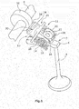
- FIG. 1 shows a perspective view of a mechanically controllable valve drive according to the invention 2.
- a gas exchange valve 4 which may be formed both as a gas inlet, and as a gas outlet valve, connected to a drag lever 6.
- a camshaft 8 is provided, which acts in the present case via a cam 10 on a transmission assembly 12, which in turn is designed such that it is in operative connection with a roller 14 of the finger lever, such that by a rotation of the camshaft 8, a lifting movement of the gas exchange valve 4 is triggered.
- the transfer assembly 12 has a transfer member 13 that has a profile rod element as coupling means 16, which has a working curve 18 which is in known manner with the roller 14 of the finger lever 6 in operative connection. On the one side of the working curve 18 opposite side 20 engages a support roller member 22, via which the transfer assembly is mounted in a cylinder head, not shown.
- the transmission member 12 further includes a housing part 24, which is designed as Ventilhubverstell Surprise and here as an actuator 25 for the profile rod member 16.
- the housing part 24 in the longitudinal direction of the transmission member adjustable plunger element 26 (see also FIG. 2 ) on.
- the housing part 24 and thus also the plunger element 26 is in Present embodiment, biased by two spring elements 28 relative to the camshaft 8 and thus with respect to the cam member 10.
- the actuator 25 is formed in the present embodiment as a hydraulic actuator.
- the plunger element 26 is in this case designed as a piston. However, it is also conceivable that a roller tappet is used for this purpose.
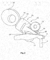
- FIG. 2 shows in a side view of the transfer assembly 12 from FIG. 1 , Clearly visible here is the profile bar member 16 which engages with its working curve 18 on the roller 14 of the finger lever 6.
- the housing part 24 is shown here transparent, so that an inwardly directed thread 30 can be seen, through which the piston-shaped plunger element 26 is guided.
- the actuator 25 may for example be connected to a not-shown high-pressure oil reservoir and accordingly adjusted so that Hubverieri from 0 to a maximum for the gas exchange valve 4 are possible. Other forms of drive for the actuator 25 are of course also conceivable.
- FIG. 3 shows an exploded perspective view of another embodiment of the actuator 25.
- the plunger element 26 is guided mechanically or hydraulically on a ramp 32.
- the ramp 32 is formed on an intermediate element 34 that is mounted in a known manner with extension pieces 36, 38 in the housing part 24 in a known manner.
- the ramp 32 can also be provided directly in the housing part 24.
Landscapes
- Engineering & Computer Science (AREA)
- General Engineering & Computer Science (AREA)
- Mechanical Engineering (AREA)
- Valve Device For Special Equipments (AREA)
- Gear-Shifting Mechanisms (AREA)
- Mechanically-Actuated Valves (AREA)
Abstract
Description
- Die Erfindung betrifft eine Übertragungsanordnung für einen mechanisch steuerbaren Ventiltrieb, die ein Übertragungsglied aufweist, das derart ausgeführt ist, dass es direkt oder indirekt über Koppelmittel mit zumindest einem Gaswechselventil in Wirkverbindung steht und das im Zylinderkopf mittels Lagermittel beweglich gelagert ist, wobei das Übertragungsglied desweiteren mit einer Nockenwelle und einer Ventilhubverstelleinrichtung in Wirkverbindung steht, derart, dass zumindest verschiedene Maximalhügel des Gaswechselventils einstellbar sind. Desweiteren betrifft die Erfindung einen mechanisch steuerbaren Ventiltrieb mit einer derartigen Übertragungsanordnung.
- Derartige Übertragungsanordnungen bzw. mechanisch steuerbare Ventiltriebe sind aus dem Stand der Technik hinlänglich bekannt. So offenbart die
EP 638706 A1 DE 10 2004 003 324 A1 , bekannt, bei einer Ventiltriebanordnung Verstellorgane vorzusehen, die unabhängig voneinander verstellt werden können mit dem Ziel, einzelne Zylinder für bestimmte Betriebszustände stillzulegen. Des Weiteren ist aus derEP 1 760 278 A2 ein Ventiltrieb bekannt, der ein Exzenterorgan besitzt, das verschiedene Kurvenläufe insbesondere für den Teilhub und den Vollhub aufweist. - Aus der
De 102 58 277 A1 ist darüber hinaus eine Übertragungsanordnung bekannt, deren Übertragungsglied mit der Nockenwelle in Wirkverbindung steht, und durch eine Ventilhubverstelleinrichtung, die in diesem Falle keine Exzenterwelle darstellt, verstellbar ist. - Alle dargestellten Ventiltriebe offenbaren eine Übertragungsanordnung, die einerseits mit einer Nockenwelle und andererseits mit einer Ventilhubverstelleinrichtung in Wirkverbindung stehen, um zumindest verschiedene Maximalhügel eines Gaswechselventils einzustellen. Unabhängig von der Anordnung der Übertragungsanordnung im Bezug auf die Nockenwelle und die Ventilhubverstelleinrichtung bedingt ein derartig ausgeführter Ventiltrieb in allen Fällen einen großen Bauraum, der im Motorraum nicht zur Verfügung steht. Darüber hinaus führt die kinematische Kopplung des Übertragungsgliedes mit der Nockenwelle, der Verstelleinrichtung und dem Gaswechselventil zu Verschleiß- und Reibungsverlusten.
- Aufgabe der Erfindung ist es daher, eine Übertragungsanordnung bzw. einen mechanisch steuerbaren Ventiltrieb zu schaffen, der die oben genannten Nachteile auf einfache und kostengünstige Weise vermeidet bzw. minimiert.
- Diese Aufgabe wird dadurch gelöst, dass die Ventilhubverstelleinrichtung in dem Übertragungsglied der Übertragungsanordnung integriert ist. Hierdurch bedingt eine derartige Übertragungsanordnung einen wesentlich geringeren Bauraum als die herkömmlichen Übertragungsanordnungen. Zudem können auf einfache Weise Kontaktpunkte mit außerhalb gelegenen Anordnungen verringert werden, wodurch Reibungsverluste minimiert werden können.
- In einer vorteilhaften Ausführungsform ist als Koppelmittel ein Profilstangenelement mit einer Arbeitskurve vorgesehen, das mit einem Schlepphebel des Gaswechselventils in Wirkverbindung steht. Durch ein derartiges Profilstangenelement wird eine besonders kompakte Ausführung der Übertragungsanordnung gewährleistet. Als Lagermittel kann ein Stützrollenorgan vorgesehen sein, das auf die der Arbeitskurve gegenüber gelegenen Seite des Profilstangenelementes angreift.
- Das Übertragungsglied ist in vorteilhafter Weise als Stellorgan mit einem Gehäuseteil für das Profilstangenelement ausgebildet. Hierbei ist es besonders vorteilhaft, wenn das Stellorgan ein in Längsrichtung des Übertragungsgliedes verstellbares Stößelelement aufweist, wobei das Stößelelement durch mindestens ein Federlement gegenüber der Nockenwelle vorgespannt ist. Hierbei kann es überdies vorteilhaft sein, wenn das Stellorgan als hydraulisches Stellorgan ausgebildet ist. Das Stößelelement kann als Kolben oder als Rollenstößel ausgebildet sein. Alternativ kann das Stößelelement als gewindegeführter Drehstößel oder auch als rampengeführter Drehstößel ausgebildet sein.
- Die Aufgabe wird ebenfalls gelöst durch einen mechanisch steuerbaren Ventiltrieb mit einer derartigen Übertragungsanordnung, wobei einem Gaswechselventil eine Übertragungsanordnung zugeordnet ist. Hierdurch ist es möglich, jedes einzelne Gaswechselventil unabhängig von den anderen Gaswechselventilen anzusteuern. Eine besonders kompakte und kostengünstige Ausführungsform eines mechanischen Ventiltriebes ergibt sich dann, wenn mindestens zwei in Reihe angeordneten Gaswechselventilen eine Übertragungsanordnung zugeordnet ist.
- Nachfolgend wird die Erfindung anhand einer Zeichnung erläutert, hierbei zeigt:
-
Figur 1 eine perspektivische Ansicht eines erfinderischen mechanischen Ventiltriebs für ein Gaswechselventil, -
Figur 2 eine perspektivische Seitenansicht einer erfinderischen Übertragungsanordnung des mechanischen Ventiltriebs ausFigur 1 , und -
Figur 3 eine perspektivische Explosivansicht einer alternativen Ausführungsform eines Stellorgans der Übertragungsanordnung. -
Figur 1 zeigt eine perspektivische Ansicht eines erfindungsgemäßen mechanisch steuerbaren Ventiltriebs 2. Auf bekannte Weise ist ein Gaswechselventil 4, das sowohl als Gaseinlass, als auch als Gasauslassventil ausgebildet sein kann, mit einem Schlepphebel 6 verbunden. Desweiteren ist eine Nockenwelle 8 vorgesehen, die im vorliegenden Fall über einen Nocken 10 auf eine Übertragungsanordnung 12 einwirkt, die wiederum derart ausgebildet ist, dass sie mit einer Rolle 14 des Schlepphebels in Wirkverbindung steht, derart, dass durch eine Drehung der Nockenwelle 8 eine Hubbewegung des Gaswechselventils 4 ausgelöst wird. - Die Übertragungsanordnung 12 besitzt ein Übertragungsglied 13, dass als Koppelmittel 16 ein Profilstangenelement aufweist, das eine Arbeitskurve 18 besitzt, die auf bekannte Weise mit der Rolle 14 des Schlepphebels 6 in Wirkverbindung steht. Auf der einen der Arbeitskurve 18 gegenüber gelegenen Seite 20 greift ein Stützrollenorgan 22 an, über das die Übertragungsanordnung in einen nicht weiter dargestellten Zylinderkopf gelagert ist. Das Übertragungsglied 12 weist desweiteren ein Gehäuseteil 24 auf, das als Ventilhubverstelleinrichtung und hierbei als Stellorgan 25 für das Profilstangenelement 16 ausgebildet ist. Hierzu weist im vorliegenden Ausführungsbeispiel das Gehäuseteil 24 ein in Längsrichtung des Übertragungsgliedes verstellbares Stößelelement 26 (siehe auch
Figur 2 ) auf. Das Gehäuseteil 24 und damit auch das Stößelelement 26 ist im vorliegenden Ausführungsbeispiel durch zwei Federelemente 28 gegenüber der Nockenwelle 8 und damit gegenüber dem Nockenelement 10 vorgespannt. Das Stellorgan 25 ist im vorliegenden Ausführungsbeispiel als hydraulisches Stellorgan ausgebildet. Das Stößelelement 26 ist hierbei als Kolben ausgebildet. Es ist jedoch auch denkbar, dass hierzu ein Rollenstößel eingesetzt wird. -
Figur 2 zeigt in einer Seitenansicht die Übertragungsanordnung 12 ausFigur 1 . Deutlich zu erkennen ist hier das Profilstangenelement 16, das mit seiner Arbeitskurve 18 auf die Rolle 14 des Schlepphebels 6 angreift. Das Gehäuseteil 24 ist hier transparent dargestellt, so dass ein nach innen gerichtetes Gewinde 30 erkennbar ist, durch das das kolbenförmige Stößelelement 26 geführt ist. Das Stellorgan 25 kann beispielsweise an ein nicht weiter dargestelltes Hockdruck-Ölreservoir angeschlossen sein und dementsprechend derart eingestellt werden, dass Hubverläufe von 0 bis maximal für das Gaswechselventil 4 möglich sind. Andere Antriebsformen für das Stellorgan 25 sind natürlich auch denkbar. -
Figur 3 zeigt eine perspektivische Explosivansicht einer weiteren Ausführungsform des Stellorgans 25. Hierbei wird das Stößelelement 26 mechanisch oder hydraulisch auf einer Rampe 32 geführt. Die Rampe 32 ist auf einem Zwischenelement 34 ausgebildet, dass mit Ansatzstücken 36, 38 formschlüssig im Gehäuseteil 24 auf bekannte Weise gelagert ist. Die Rampe 32 kann natürlich auch direkt im Gehäuseteil 24 vorgesehen sein.
Claims (11)
- Übertragungsanordnung für einen mechanisch steuerbaren Ventiltrieb (2), die ein Übertragungsglied (13) aufweist, das derart ausgeführt ist, dass es direkt oder indirekt über Koppelmittel (6. 14, 16, 18) mit zumindest einem Gaswechselventil (4) in Wirkverbindung steht und das im Zylinderkopf mittels Lagermittel (22) beweglich gelagert ist, wobei das Übertragungsglied (13) desweiteren mit einer Nockenwelle (8) und einer Ventilhubverstelleinrichtung (25) in Wirkverbindung steht, derart, dass zumindest verschiedene Maximalhübe des Gaswechselventils (4) einstellbar sind,
dadurch gekennzeichnet, dass die Ventilhubverstelleinrichtung (25) in dem Übertragungsglied (13) der Übertragungsanordnung (12) integriert ist. - Übertragungsanordnung nach Anspruch 1, dadurch gekennzeichnet, dass als Koppelmittel ein Profilstangenelement (16) mit einer Arbeitskurve (18) vorgesehen ist, das mit einem Schlepphebel (6) des Gaswechselventils in Wirkverbindung steht.
- Übertragungsanordnung nach Anspruch 2, dadurch gekennzeichnet, dass als Lagermittel ein Stützrollenorgan (22) vorgesehen ist, das auf die der Arbeitskurve (18) gegenüber gelegenen Seite (20) des Profilstangenelementes (16) angreift.
- Übertragungsanordnung nach einem der Ansprüche 1 - 3, dadurch gekennzeichnet, dass das Übertragungsglied (13) als Stellorgan (25) mit einem Gehäuseteil (24) für das Profilstangenelement (16) ausgebildet ist.
- Übertragungsanordnung nach Anspruch 4, dadurch gekennzeichnet, dass das Stellorgan (24) ein in Längsrichtung des Übertragungsgliedes (13) verstellbares Stößelelement (26) aufweist, wobei das Stößelelement (26) durch mindestens ein Federelement (28) gegenüber der Nockenwelle vorgespannt ist.
- Übertragungsanordnung nach Anspruch 4 oder 5, dadurch gekennzeichnet, dass das Stellorgan (24) als hydraulisches Stellorgan ausgebildet ist.
- Übertragungsanordnung nach Anspruch 5 oder 6, dadurch gekennzeichnet, dass das Stößelelement (26) als Kolben oder als Rollenstößel ausgebildet ist.
- Übertragungsanordnung nach Anspruch 5 oder 6, dadurch gekennzeichnet, dass das Stößelelement (26) als gewindegeführter Drehstößel ausgebildet ist.
- Übertragungsanordnung nach Anspruch 5 oder 6, dadurch gekennzeichnet, dass das Stößelelement (26) als rampengeführter Drehstößel ausgebildet ist.
- Mechanisch steuerbarer Ventiltrieb mit einer Übertragungsanordnung nach einem der vorhergehenden Ansprüche, dadurch gekennzeichnet, dass einem Gaswechselventil (4) eine Übertragungsanordnung (12) zugeordnet ist.
- Mechanisch steuerbarer Ventiltrieb mit einer Übertragungsanordnung nach einem der Ansprüche 1-8, dadurch gekennzeichnet, dass mindestens zwei in Reihe angeordneten Gaswechselventilen (4) eine Übertragungsanordnung (12) zugeordnet ist.
Applications Claiming Priority (1)
| Application Number | Priority Date | Filing Date | Title |
|---|---|---|---|
| DE102013113815.2A DE102013113815A1 (de) | 2013-12-11 | 2013-12-11 | Übertragungsanordnung für einen mechanisch steuerbaren Ventiltrieb |
Publications (3)
| Publication Number | Publication Date |
|---|---|
| EP2905437A2 true EP2905437A2 (de) | 2015-08-12 |
| EP2905437A3 EP2905437A3 (de) | 2016-02-10 |
| EP2905437B1 EP2905437B1 (de) | 2017-02-01 |
Family
ID=51726394
Family Applications (1)
| Application Number | Title | Priority Date | Filing Date |
|---|---|---|---|
| EP14188789.3A Not-in-force EP2905437B1 (de) | 2013-12-11 | 2014-10-14 | Übertragungsanordnung für einen mechanisch steuerbaren Ventiltrieb |
Country Status (3)
| Country | Link |
|---|---|
| US (1) | US9464540B2 (de) |
| EP (1) | EP2905437B1 (de) |
| DE (1) | DE102013113815A1 (de) |
Families Citing this family (2)
| Publication number | Priority date | Publication date | Assignee | Title |
|---|---|---|---|---|
| EP2884086B1 (de) * | 2013-12-11 | 2017-12-20 | Borgwarner Inc. | Aktuator mit Ventilrücksteller |
| DE102015224466B4 (de) * | 2015-12-07 | 2020-10-08 | Vitesco Technologies GmbH | Ventil |
Citations (3)
| Publication number | Priority date | Publication date | Assignee | Title |
|---|---|---|---|---|
| EP0638706A1 (de) | 1993-08-05 | 1995-02-15 | Bayerische Motoren Werke Aktiengesellschaft | Ventiltrieb einer Brennkraftmaschine |
| DE102004003324A1 (de) | 2003-01-23 | 2004-08-05 | Dana Corp., Toledo | Differentialvorrichtung |
| EP1760278A2 (de) | 2005-08-30 | 2007-03-07 | Bayerische Motoren Werke Aktiengesellschaft | Hubvariabler Ventiltrieb für eine Brennkraftmaschine |
Family Cites Families (18)
| Publication number | Priority date | Publication date | Assignee | Title |
|---|---|---|---|---|
| DE3115422A1 (de) * | 1981-04-16 | 1982-11-11 | M.A.N. Maschinenfabrik Augsburg-Nürnberg AG, 8500 Nürnberg | Hydraulische einrichtung zum betaetigen von gaswechselventilen |
| US4759321A (en) * | 1985-06-24 | 1988-07-26 | Nissan Motor Co., Ltd. | Valve timing arrangement for internal combustion engine having multiple inlet valves per cylinder |
| WO1993018284A1 (de) * | 1992-03-06 | 1993-09-16 | F. Porsche Aktiengesellschaft | Zylinderkopf für eine brennkraftmaschine |
| DE4235620C2 (de) * | 1992-10-22 | 1999-09-23 | Hydraulik Ring Gmbh | Ventilhubverstelleinrichtung für Brennkraftmaschinen und Kompressoren |
| US6076491A (en) * | 1994-05-03 | 2000-06-20 | Lotus Cars Limited | Valve control mechanism |
| EP0759119B1 (de) * | 1994-05-03 | 1999-11-03 | Lotus Car Limited | Ventilantriebsvorrichtung |
| DE10012400A1 (de) * | 2000-03-15 | 2001-09-20 | Iav Gmbh | Vollvariabler mechanischer Ventiltrieb, insbesondere für Gaswechselventile |
| EP1255027B1 (de) * | 2001-05-03 | 2004-08-04 | STS System Technology Services GmbH | Mechanische Regelung der Hubverstellung des Einlassventils eines Verbrennungsmotors |
| US6769387B2 (en) * | 2002-10-19 | 2004-08-03 | General Motors Corporation | Compact two-step rocker arm assembly |
| DE10258277A1 (de) | 2002-12-13 | 2004-06-24 | Mahle Ventiltrieb Gmbh | Steuereinrichtung für Gaswechselventile eines Verbrennungsmotors |
| WO2005008052A1 (ja) * | 2003-07-22 | 2005-01-27 | Toyota Jidosha Kabushiki Kaisha | 内燃機関の気筒間バラツキ検出装置およびバンク間バラツキ検出装置 |
| DE102004040652A1 (de) * | 2004-08-20 | 2006-02-23 | Rolf Jung | Vollvariabler fünfgliedriger Ventiltrieb einer Brennkraftmaschine |
| US6966291B1 (en) * | 2004-10-28 | 2005-11-22 | Delphi Technologies, Inc. | Latch timing mechanism for a two-step roller finger cam follower |
| US7305951B2 (en) * | 2005-05-09 | 2007-12-11 | Delphi Technologies, Inc. | Two-step roller finger follower |
| JP4469326B2 (ja) * | 2005-11-07 | 2010-05-26 | 株式会社オティックス | 可変動弁機構 |
| US7730861B2 (en) * | 2007-03-13 | 2010-06-08 | Gm Global Technology Operations, Inc. | Two-step rocker arm assembly |
| DE102009035404A1 (de) * | 2009-07-30 | 2011-02-03 | Schaeffler Technologies Gmbh & Co. Kg | Verbrennungsmotor mit elektrohydraulisch hubvariabler Ventilbetätigung |
| US8689753B2 (en) * | 2010-06-11 | 2014-04-08 | Schaeffler Technologies AG & Co. KG | Locking mechanism for variable actuation using a shuttle pin and return spring |
-
2013
- 2013-12-11 DE DE102013113815.2A patent/DE102013113815A1/de not_active Withdrawn
-
2014
- 2014-10-14 EP EP14188789.3A patent/EP2905437B1/de not_active Not-in-force
- 2014-12-08 US US14/562,786 patent/US9464540B2/en not_active Expired - Fee Related
Patent Citations (3)
| Publication number | Priority date | Publication date | Assignee | Title |
|---|---|---|---|---|
| EP0638706A1 (de) | 1993-08-05 | 1995-02-15 | Bayerische Motoren Werke Aktiengesellschaft | Ventiltrieb einer Brennkraftmaschine |
| DE102004003324A1 (de) | 2003-01-23 | 2004-08-05 | Dana Corp., Toledo | Differentialvorrichtung |
| EP1760278A2 (de) | 2005-08-30 | 2007-03-07 | Bayerische Motoren Werke Aktiengesellschaft | Hubvariabler Ventiltrieb für eine Brennkraftmaschine |
Also Published As
| Publication number | Publication date |
|---|---|
| US20150159519A1 (en) | 2015-06-11 |
| DE102013113815A1 (de) | 2015-06-11 |
| EP2905437B1 (de) | 2017-02-01 |
| EP2905437A3 (de) | 2016-02-10 |
| US9464540B2 (en) | 2016-10-11 |
Similar Documents
| Publication | Publication Date | Title |
|---|---|---|
| EP3170997B1 (de) | Variabler ventiltrieb mit einem kipphebel | |
| DE112004001450B4 (de) | Vorrichtung für eine Brennkraftmaschine | |
| DE19908286B4 (de) | Variable Ventilsteuerung für Brennkraftmaschinen | |
| DE112015001969B4 (de) | Variable Ventiltriebvorrichtung für Verbrennungsmotoren | |
| DE102016212480A1 (de) | Variabler Ventiltrieb eines Verbrennungskolbenmotors | |
| DE102012012150B4 (de) | Schlepphebelanordnung und Verbrennungsmotor | |
| AT519140B1 (de) | Längenverstellbares Pleuel mit mechanischer Verstellung | |
| DE102010060826B4 (de) | Variabler-Ventilhub-Vorrichtung | |
| EP2905437B1 (de) | Übertragungsanordnung für einen mechanisch steuerbaren Ventiltrieb | |
| EP2668376B1 (de) | Vorrichtung zur variablen ventilhubverstellung | |
| DE10323665B4 (de) | Variable Ventilhubvorrichtung zur Hubverstellung der Gaswechselventile einer Verbrennungskraftmaschine | |
| EP1588027B1 (de) | Hydraulischer mitnehmerkipphebel | |
| DE10205216B4 (de) | Betätigungsvorrichtung mit variablem Hub für ein oszilierendes Bauteil | |
| EP2171221B1 (de) | Schlepphebel für einen ventiltrieb einer brennkraftmaschine | |
| EP3167168B1 (de) | Mechanisch steuerbarer ventiltrieb | |
| DE10137072A1 (de) | Vorrichtung zum Antrieb von wenigstens einem Ventil eines Hubkolbenmotors | |
| DE102006002145A1 (de) | Gaswechselventilbetätigungsvorrichtung | |
| DE102012004413B4 (de) | Mechanisch steuerbare Ventiltriebanordnung | |
| EP3073072A2 (de) | Mechanisch steuerbarer ventiltrieb sowie mechanisch steuerbare ventiltriebanordnung | |
| DE102011014744B4 (de) | Mechanisch steuerbarer Ventiltrieb sowie mechanisch steuerbare Ventiltriebanordnung | |
| AT514535B1 (de) | Ventilbetätigungseinrichtung | |
| DE102006011981A1 (de) | Einrichtung zur variablen Ansteuerung von Gaswechselventilen einer Hubkolbenbrennkraftmaschine | |
| DE102010009909B3 (de) | Hubkolbenmaschine | |
| DE202011102824U1 (de) | Federsystem | |
| AT521670A1 (de) | Variable ventiltriebeinrichtung |
Legal Events
| Date | Code | Title | Description |
|---|---|---|---|
| PUAI | Public reference made under article 153(3) epc to a published international application that has entered the european phase |
Free format text: ORIGINAL CODE: 0009012 |
|
| AK | Designated contracting states |
Kind code of ref document: A2 Designated state(s): AL AT BE BG CH CY CZ DE DK EE ES FI FR GB GR HR HU IE IS IT LI LT LU LV MC MK MT NL NO PL PT RO RS SE SI SK SM TR |
|
| AX | Request for extension of the european patent |
Extension state: BA ME |
|
| PUAL | Search report despatched |
Free format text: ORIGINAL CODE: 0009013 |
|
| AK | Designated contracting states |
Kind code of ref document: A3 Designated state(s): AL AT BE BG CH CY CZ DE DK EE ES FI FR GB GR HR HU IE IS IT LI LT LU LV MC MK MT NL NO PL PT RO RS SE SI SK SM TR |
|
| AX | Request for extension of the european patent |
Extension state: BA ME |
|
| RIC1 | Information provided on ipc code assigned before grant |
Ipc: F16K 31/524 20060101ALI20160107BHEP Ipc: F16K 1/54 20060101ALI20160107BHEP Ipc: F01L 13/00 20060101AFI20160107BHEP Ipc: F01L 1/12 20060101ALI20160107BHEP |
|
| 17P | Request for examination filed |
Effective date: 20160711 |
|
| RBV | Designated contracting states (corrected) |
Designated state(s): AL AT BE BG CH CY CZ DE DK EE ES FI FR GB GR HR HU IE IS IT LI LT LU LV MC MK MT NL NO PL PT RO RS SE SI SK SM TR |
|
| GRAP | Despatch of communication of intention to grant a patent |
Free format text: ORIGINAL CODE: EPIDOSNIGR1 |
|
| INTG | Intention to grant announced |
Effective date: 20161020 |
|
| STAA | Information on the status of an ep patent application or granted ep patent |
Free format text: STATUS: GRANT OF PATENT IS INTENDED |
|
| GRAS | Grant fee paid |
Free format text: ORIGINAL CODE: EPIDOSNIGR3 |
|
| GRAA | (expected) grant |
Free format text: ORIGINAL CODE: 0009210 |
|
| STAA | Information on the status of an ep patent application or granted ep patent |
Free format text: STATUS: THE PATENT HAS BEEN GRANTED |
|
| AK | Designated contracting states |
Kind code of ref document: B1 Designated state(s): AL AT BE BG CH CY CZ DE DK EE ES FI FR GB GR HR HU IE IS IT LI LT LU LV MC MK MT NL NO PL PT RO RS SE SI SK SM TR |
|
| REG | Reference to a national code |
Ref country code: GB Ref legal event code: FG4D Free format text: NOT ENGLISH |
|
| REG | Reference to a national code |
Ref country code: CH Ref legal event code: EP Ref country code: AT Ref legal event code: REF Ref document number: 865797 Country of ref document: AT Kind code of ref document: T Effective date: 20170215 |
|
| REG | Reference to a national code |
Ref country code: IE Ref legal event code: FG4D Free format text: LANGUAGE OF EP DOCUMENT: GERMAN |
|
| REG | Reference to a national code |
Ref country code: DE Ref legal event code: R096 Ref document number: 502014002600 Country of ref document: DE |
|
| REG | Reference to a national code |
Ref country code: NL Ref legal event code: MP Effective date: 20170201 |
|
| REG | Reference to a national code |
Ref country code: LT Ref legal event code: MG4D |
|
| PG25 | Lapsed in a contracting state [announced via postgrant information from national office to epo] |
Ref country code: HR Free format text: LAPSE BECAUSE OF FAILURE TO SUBMIT A TRANSLATION OF THE DESCRIPTION OR TO PAY THE FEE WITHIN THE PRESCRIBED TIME-LIMIT Effective date: 20170201 Ref country code: NO Free format text: LAPSE BECAUSE OF FAILURE TO SUBMIT A TRANSLATION OF THE DESCRIPTION OR TO PAY THE FEE WITHIN THE PRESCRIBED TIME-LIMIT Effective date: 20170501 Ref country code: IS Free format text: LAPSE BECAUSE OF FAILURE TO SUBMIT A TRANSLATION OF THE DESCRIPTION OR TO PAY THE FEE WITHIN THE PRESCRIBED TIME-LIMIT Effective date: 20170601 Ref country code: FI Free format text: LAPSE BECAUSE OF FAILURE TO SUBMIT A TRANSLATION OF THE DESCRIPTION OR TO PAY THE FEE WITHIN THE PRESCRIBED TIME-LIMIT Effective date: 20170201 Ref country code: GR Free format text: LAPSE BECAUSE OF FAILURE TO SUBMIT A TRANSLATION OF THE DESCRIPTION OR TO PAY THE FEE WITHIN THE PRESCRIBED TIME-LIMIT Effective date: 20170502 Ref country code: LT Free format text: LAPSE BECAUSE OF FAILURE TO SUBMIT A TRANSLATION OF THE DESCRIPTION OR TO PAY THE FEE WITHIN THE PRESCRIBED TIME-LIMIT Effective date: 20170201 |
|
| PG25 | Lapsed in a contracting state [announced via postgrant information from national office to epo] |
Ref country code: ES Free format text: LAPSE BECAUSE OF FAILURE TO SUBMIT A TRANSLATION OF THE DESCRIPTION OR TO PAY THE FEE WITHIN THE PRESCRIBED TIME-LIMIT Effective date: 20170201 Ref country code: LV Free format text: LAPSE BECAUSE OF FAILURE TO SUBMIT A TRANSLATION OF THE DESCRIPTION OR TO PAY THE FEE WITHIN THE PRESCRIBED TIME-LIMIT Effective date: 20170201 Ref country code: RS Free format text: LAPSE BECAUSE OF FAILURE TO SUBMIT A TRANSLATION OF THE DESCRIPTION OR TO PAY THE FEE WITHIN THE PRESCRIBED TIME-LIMIT Effective date: 20170201 Ref country code: PT Free format text: LAPSE BECAUSE OF FAILURE TO SUBMIT A TRANSLATION OF THE DESCRIPTION OR TO PAY THE FEE WITHIN THE PRESCRIBED TIME-LIMIT Effective date: 20170601 Ref country code: SE Free format text: LAPSE BECAUSE OF FAILURE TO SUBMIT A TRANSLATION OF THE DESCRIPTION OR TO PAY THE FEE WITHIN THE PRESCRIBED TIME-LIMIT Effective date: 20170201 Ref country code: PL Free format text: LAPSE BECAUSE OF FAILURE TO SUBMIT A TRANSLATION OF THE DESCRIPTION OR TO PAY THE FEE WITHIN THE PRESCRIBED TIME-LIMIT Effective date: 20170201 Ref country code: BG Free format text: LAPSE BECAUSE OF FAILURE TO SUBMIT A TRANSLATION OF THE DESCRIPTION OR TO PAY THE FEE WITHIN THE PRESCRIBED TIME-LIMIT Effective date: 20170501 Ref country code: NL Free format text: LAPSE BECAUSE OF FAILURE TO SUBMIT A TRANSLATION OF THE DESCRIPTION OR TO PAY THE FEE WITHIN THE PRESCRIBED TIME-LIMIT Effective date: 20170201 |
|
| PG25 | Lapsed in a contracting state [announced via postgrant information from national office to epo] |
Ref country code: EE Free format text: LAPSE BECAUSE OF FAILURE TO SUBMIT A TRANSLATION OF THE DESCRIPTION OR TO PAY THE FEE WITHIN THE PRESCRIBED TIME-LIMIT Effective date: 20170201 Ref country code: RO Free format text: LAPSE BECAUSE OF FAILURE TO SUBMIT A TRANSLATION OF THE DESCRIPTION OR TO PAY THE FEE WITHIN THE PRESCRIBED TIME-LIMIT Effective date: 20170201 Ref country code: CZ Free format text: LAPSE BECAUSE OF FAILURE TO SUBMIT A TRANSLATION OF THE DESCRIPTION OR TO PAY THE FEE WITHIN THE PRESCRIBED TIME-LIMIT Effective date: 20170201 Ref country code: IT Free format text: LAPSE BECAUSE OF FAILURE TO SUBMIT A TRANSLATION OF THE DESCRIPTION OR TO PAY THE FEE WITHIN THE PRESCRIBED TIME-LIMIT Effective date: 20170201 Ref country code: SK Free format text: LAPSE BECAUSE OF FAILURE TO SUBMIT A TRANSLATION OF THE DESCRIPTION OR TO PAY THE FEE WITHIN THE PRESCRIBED TIME-LIMIT Effective date: 20170201 |
|
| REG | Reference to a national code |
Ref country code: DE Ref legal event code: R097 Ref document number: 502014002600 Country of ref document: DE |
|
| PG25 | Lapsed in a contracting state [announced via postgrant information from national office to epo] |
Ref country code: DK Free format text: LAPSE BECAUSE OF FAILURE TO SUBMIT A TRANSLATION OF THE DESCRIPTION OR TO PAY THE FEE WITHIN THE PRESCRIBED TIME-LIMIT Effective date: 20170201 Ref country code: SM Free format text: LAPSE BECAUSE OF FAILURE TO SUBMIT A TRANSLATION OF THE DESCRIPTION OR TO PAY THE FEE WITHIN THE PRESCRIBED TIME-LIMIT Effective date: 20170201 |
|
| PLBE | No opposition filed within time limit |
Free format text: ORIGINAL CODE: 0009261 |
|
| STAA | Information on the status of an ep patent application or granted ep patent |
Free format text: STATUS: NO OPPOSITION FILED WITHIN TIME LIMIT |
|
| 26N | No opposition filed |
Effective date: 20171103 |
|
| PG25 | Lapsed in a contracting state [announced via postgrant information from national office to epo] |
Ref country code: SI Free format text: LAPSE BECAUSE OF FAILURE TO SUBMIT A TRANSLATION OF THE DESCRIPTION OR TO PAY THE FEE WITHIN THE PRESCRIBED TIME-LIMIT Effective date: 20170201 |
|
| PG25 | Lapsed in a contracting state [announced via postgrant information from national office to epo] |
Ref country code: MC Free format text: LAPSE BECAUSE OF FAILURE TO SUBMIT A TRANSLATION OF THE DESCRIPTION OR TO PAY THE FEE WITHIN THE PRESCRIBED TIME-LIMIT Effective date: 20170201 |
|
| REG | Reference to a national code |
Ref country code: CH Ref legal event code: PL |
|
| REG | Reference to a national code |
Ref country code: IE Ref legal event code: MM4A |
|
| REG | Reference to a national code |
Ref country code: FR Ref legal event code: ST Effective date: 20180629 |
|
| PG25 | Lapsed in a contracting state [announced via postgrant information from national office to epo] |
Ref country code: CH Free format text: LAPSE BECAUSE OF NON-PAYMENT OF DUE FEES Effective date: 20171031 Ref country code: LU Free format text: LAPSE BECAUSE OF NON-PAYMENT OF DUE FEES Effective date: 20171014 Ref country code: LI Free format text: LAPSE BECAUSE OF NON-PAYMENT OF DUE FEES Effective date: 20171031 |
|
| REG | Reference to a national code |
Ref country code: BE Ref legal event code: MM Effective date: 20171031 |
|
| PG25 | Lapsed in a contracting state [announced via postgrant information from national office to epo] |
Ref country code: BE Free format text: LAPSE BECAUSE OF NON-PAYMENT OF DUE FEES Effective date: 20171031 Ref country code: FR Free format text: LAPSE BECAUSE OF NON-PAYMENT OF DUE FEES Effective date: 20171031 |
|
| PG25 | Lapsed in a contracting state [announced via postgrant information from national office to epo] |
Ref country code: MT Free format text: LAPSE BECAUSE OF FAILURE TO SUBMIT A TRANSLATION OF THE DESCRIPTION OR TO PAY THE FEE WITHIN THE PRESCRIBED TIME-LIMIT Effective date: 20170201 |
|
| PG25 | Lapsed in a contracting state [announced via postgrant information from national office to epo] |
Ref country code: IE Free format text: LAPSE BECAUSE OF NON-PAYMENT OF DUE FEES Effective date: 20171014 |
|
| GBPC | Gb: european patent ceased through non-payment of renewal fee |
Effective date: 20181014 |
|
| PG25 | Lapsed in a contracting state [announced via postgrant information from national office to epo] |
Ref country code: HU Free format text: LAPSE BECAUSE OF FAILURE TO SUBMIT A TRANSLATION OF THE DESCRIPTION OR TO PAY THE FEE WITHIN THE PRESCRIBED TIME-LIMIT; INVALID AB INITIO Effective date: 20141014 |
|
| PG25 | Lapsed in a contracting state [announced via postgrant information from national office to epo] |
Ref country code: CY Free format text: LAPSE BECAUSE OF FAILURE TO SUBMIT A TRANSLATION OF THE DESCRIPTION OR TO PAY THE FEE WITHIN THE PRESCRIBED TIME-LIMIT Effective date: 20170201 Ref country code: GB Free format text: LAPSE BECAUSE OF NON-PAYMENT OF DUE FEES Effective date: 20181014 |
|
| PG25 | Lapsed in a contracting state [announced via postgrant information from national office to epo] |
Ref country code: MK Free format text: LAPSE BECAUSE OF FAILURE TO SUBMIT A TRANSLATION OF THE DESCRIPTION OR TO PAY THE FEE WITHIN THE PRESCRIBED TIME-LIMIT Effective date: 20170201 |
|
| REG | Reference to a national code |
Ref country code: DE Ref legal event code: R082 Ref document number: 502014002600 Country of ref document: DE Representative=s name: TERPATENT PARTGMBB, DE Ref country code: DE Ref legal event code: R082 Ref document number: 502014002600 Country of ref document: DE Representative=s name: TERPATENT PATENTANWAELTE TER SMITTEN EBERLEIN-, DE |
|
| PG25 | Lapsed in a contracting state [announced via postgrant information from national office to epo] |
Ref country code: TR Free format text: LAPSE BECAUSE OF FAILURE TO SUBMIT A TRANSLATION OF THE DESCRIPTION OR TO PAY THE FEE WITHIN THE PRESCRIBED TIME-LIMIT Effective date: 20170201 |
|
| PG25 | Lapsed in a contracting state [announced via postgrant information from national office to epo] |
Ref country code: AL Free format text: LAPSE BECAUSE OF FAILURE TO SUBMIT A TRANSLATION OF THE DESCRIPTION OR TO PAY THE FEE WITHIN THE PRESCRIBED TIME-LIMIT Effective date: 20170201 |
|
| REG | Reference to a national code |
Ref country code: AT Ref legal event code: MM01 Ref document number: 865797 Country of ref document: AT Kind code of ref document: T Effective date: 20191014 |
|
| PG25 | Lapsed in a contracting state [announced via postgrant information from national office to epo] |
Ref country code: AT Free format text: LAPSE BECAUSE OF NON-PAYMENT OF DUE FEES Effective date: 20191014 |
|
| PGFP | Annual fee paid to national office [announced via postgrant information from national office to epo] |
Ref country code: DE Payment date: 20241022 Year of fee payment: 11 |
|
| REG | Reference to a national code |
Ref country code: DE Ref legal event code: R119 Ref document number: 502014002600 Country of ref document: DE |
|
| PG25 | Lapsed in a contracting state [announced via postgrant information from national office to epo] |
Ref country code: DE Free format text: LAPSE BECAUSE OF NON-PAYMENT OF DUE FEES Effective date: 20260501 |