EP1096117A1 - Procédé de diagnostic d'un système de purification des gaz d'échappement pour moteur à combustion interne - Google Patents
Procédé de diagnostic d'un système de purification des gaz d'échappement pour moteur à combustion interne Download PDFInfo
- Publication number
- EP1096117A1 EP1096117A1 EP00123147A EP00123147A EP1096117A1 EP 1096117 A1 EP1096117 A1 EP 1096117A1 EP 00123147 A EP00123147 A EP 00123147A EP 00123147 A EP00123147 A EP 00123147A EP 1096117 A1 EP1096117 A1 EP 1096117A1
- Authority
- EP
- European Patent Office
- Prior art keywords
- catalyst
- temperature
- stage
- nom
- input
- Prior art date
- Legal status (The legal status is an assumption and is not a legal conclusion. Google has not performed a legal analysis and makes no representation as to the accuracy of the status listed.)
- Granted
Links
Images


Classifications
-
- F—MECHANICAL ENGINEERING; LIGHTING; HEATING; WEAPONS; BLASTING
- F01—MACHINES OR ENGINES IN GENERAL; ENGINE PLANTS IN GENERAL; STEAM ENGINES
- F01N—GAS-FLOW SILENCERS OR EXHAUST APPARATUS FOR MACHINES OR ENGINES IN GENERAL; GAS-FLOW SILENCERS OR EXHAUST APPARATUS FOR INTERNAL-COMBUSTION ENGINES
- F01N11/00—Monitoring or diagnostic devices for exhaust-gas treatment apparatus
- F01N11/002—Monitoring or diagnostic devices for exhaust-gas treatment apparatus the diagnostic devices measuring or estimating temperature or pressure in, or downstream of the exhaust apparatus
- F01N11/005—Monitoring or diagnostic devices for exhaust-gas treatment apparatus the diagnostic devices measuring or estimating temperature or pressure in, or downstream of the exhaust apparatus the temperature or pressure being estimated, e.g. by means of a theoretical model
-
- F—MECHANICAL ENGINEERING; LIGHTING; HEATING; WEAPONS; BLASTING
- F01—MACHINES OR ENGINES IN GENERAL; ENGINE PLANTS IN GENERAL; STEAM ENGINES
- F01N—GAS-FLOW SILENCERS OR EXHAUST APPARATUS FOR MACHINES OR ENGINES IN GENERAL; GAS-FLOW SILENCERS OR EXHAUST APPARATUS FOR INTERNAL-COMBUSTION ENGINES
- F01N11/00—Monitoring or diagnostic devices for exhaust-gas treatment apparatus
- F01N11/002—Monitoring or diagnostic devices for exhaust-gas treatment apparatus the diagnostic devices measuring or estimating temperature or pressure in, or downstream of the exhaust apparatus
-
- F—MECHANICAL ENGINEERING; LIGHTING; HEATING; WEAPONS; BLASTING
- F01—MACHINES OR ENGINES IN GENERAL; ENGINE PLANTS IN GENERAL; STEAM ENGINES
- F01N—GAS-FLOW SILENCERS OR EXHAUST APPARATUS FOR MACHINES OR ENGINES IN GENERAL; GAS-FLOW SILENCERS OR EXHAUST APPARATUS FOR INTERNAL-COMBUSTION ENGINES
- F01N13/00—Exhaust or silencing apparatus characterised by constructional features
- F01N13/009—Exhaust or silencing apparatus characterised by constructional features having two or more separate purifying devices arranged in series
-
- F—MECHANICAL ENGINEERING; LIGHTING; HEATING; WEAPONS; BLASTING
- F01—MACHINES OR ENGINES IN GENERAL; ENGINE PLANTS IN GENERAL; STEAM ENGINES
- F01N—GAS-FLOW SILENCERS OR EXHAUST APPARATUS FOR MACHINES OR ENGINES IN GENERAL; GAS-FLOW SILENCERS OR EXHAUST APPARATUS FOR INTERNAL-COMBUSTION ENGINES
- F01N13/00—Exhaust or silencing apparatus characterised by constructional features
- F01N13/009—Exhaust or silencing apparatus characterised by constructional features having two or more separate purifying devices arranged in series
- F01N13/0093—Exhaust or silencing apparatus characterised by constructional features having two or more separate purifying devices arranged in series the purifying devices are of the same type
-
- F—MECHANICAL ENGINEERING; LIGHTING; HEATING; WEAPONS; BLASTING
- F01—MACHINES OR ENGINES IN GENERAL; ENGINE PLANTS IN GENERAL; STEAM ENGINES
- F01N—GAS-FLOW SILENCERS OR EXHAUST APPARATUS FOR MACHINES OR ENGINES IN GENERAL; GAS-FLOW SILENCERS OR EXHAUST APPARATUS FOR INTERNAL-COMBUSTION ENGINES
- F01N2550/00—Monitoring or diagnosing the deterioration of exhaust systems
- F01N2550/02—Catalytic activity of catalytic converters
-
- Y—GENERAL TAGGING OF NEW TECHNOLOGICAL DEVELOPMENTS; GENERAL TAGGING OF CROSS-SECTIONAL TECHNOLOGIES SPANNING OVER SEVERAL SECTIONS OF THE IPC; TECHNICAL SUBJECTS COVERED BY FORMER USPC CROSS-REFERENCE ART COLLECTIONS [XRACs] AND DIGESTS
- Y02—TECHNOLOGIES OR APPLICATIONS FOR MITIGATION OR ADAPTATION AGAINST CLIMATE CHANGE
- Y02T—CLIMATE CHANGE MITIGATION TECHNOLOGIES RELATED TO TRANSPORTATION
- Y02T10/00—Road transport of goods or passengers
- Y02T10/10—Internal combustion engine [ICE] based vehicles
- Y02T10/40—Engine management systems
Definitions
- the present invention relates to a method for the diagnosis of an exhaust gas purification system for an internal combustion engine.
- exhaust gas purification systems that are intended to minimise emissions of polluting substances, for instance nitrogen oxides, carbon monoxide and non-combusted hydrocarbons.
- the system 1 is connected to an internal combustion engine 2 and comprises a pre-catalyst 3, disposed along an exhaust duct 4 to the rear of the engine 2, and a main catalyst 5, disposed further downstream.
- the pre-catalyst 3 is typically a three-way catalyst or TWC.
- An output temperature sensor 8 also measures the temperature of the exhaust gases at the output of the pre-catalyst 3.
- the oxygen sensors 6 and 7 generate a first and respectively a second exhaust gas composition signal V 1 and V 2 , representative of titres ⁇ I and ⁇ F at the input and output of the pre-catalyst 3, while the temperature sensor 8 supplies an output temperature signal V o representative of the output temperature T o of the exhaust gases on output from the pre-catalyst 3.
- These signals are supplied as input to a control unit 10 that further receives a plurality of engine-related parameters (for instance number of revolutions RPM and load L), on the basis of which the operating point of the engine 2 can be determined.
- the control unit 10 performs a diagnostic algorithm and generates as output an error signal E, for instance of logic type, which assumes a first logic value when a malfunction of the system 1 is detected.
- the pre-catalyst 3 and the main catalyst 5 are the most important components of the system 1 and it is therefore fundamental to ensure that their efficiency is constantly kept above a minimum threshold. It is therefore necessary to provide methods that make it possible to ascertain whether, as a result of ageing or malfunction, there has been any deterioration of their performance and whether maintenance work needs to be carried out to ensure that the system is returned to normal operation.
- Diagnosis of the pre-catalyst 3 is possible only during ignition transients of the engine 2, since the main catalyst 5 requires longer times to achieve maximum efficiency. Therefore, in the initial phases of operation, during which the pre-catalyst 3 and the main catalyst 5 are being brought to respective operating temperatures, the removal of the polluting emissions may be attributed completely to the action of the pre-catalyst 3 which reaches conditions of maximum efficiency more rapidly.
- the object of the present invention is to provide a diagnostic method which is free from the drawbacks described above and is, in particular, reliable and not influenced by the ageing of the pre-catalyst.
- the present invention therefore relates to a method for the diagnosis of an exhaust gas purification system in an internal combustion engine, comprising a pre-catalyst and a main catalyst disposed along an exhaust duct of an internal combustion engine, first temperature detection means disposed at the input of the pre-catalyst and generating a first temperature signal representative of an input temperature T I of the exhaust gases at the input of this pre-catalyst, second temperature detection means disposed at the output of the pre-catalyst and generating a second temperature signal representative of an output temperature T o of the exhaust gases at the output of this pre-catalyst, oxygen sensor means, disposed at the input of the pre-catalyst and generating an exhaust gas composition signal, representative of an input oxygen titre ⁇ I , a control unit receiving as input the first and second temperature signals and the exhaust gas composition signal and supplying as output an error signal, characterised in that it comprises the stages of:
- Fig. 2 shows an exhaust gas purification system 1' which implements the diagnostic method of the present invention.
- members identical to those already described with reference to Fig. 1 bear the same reference numerals.
- the system 1' comprises the same members as the system 1 of Fig. 1 and differs in that it further comprises an input temperature sensor 12 disposed at the input of the pre-catalyst 3, which generates and supplies to the control unit 10 a signal V I representative of the input temperature T I .
- the pre-catalyst 3 When the engine 2 is started, the pre-catalyst 3 is brought to an operating temperature T OP , for instance equal to 350°C, giving rise to highly exothermic oxidation reactions.
- the exhaust gases are therefore heated as they pass into the pre-catalyst 3 and, as shown in Fig. 3, from a first instant ⁇ 1 , the output temperature T o (shown in Fig. 3 by a Continuous line) increases with respect to the input temperature T I (dot-dashed line).
- Fig. 4 shows a comparison between the curves of an output temperature T O1 from a new pre-catalyst 3 (shown by a continuous line), i.e. operating in nominal conditions and with nominal performance, and an output temperature T O2 from a worn pre-catalyst 3 (shown by a dashed line). Since the area under each curve is representative of the heat supplied to the exhaust gases in the corresponding operating conditions, it will be appreciated that the quantity of heat that the pre-catalyst 3 is able to supply decreases with the ageing of this pre-catalyst 3.
- the flow of air M A is known on the basis of the operating point of the engine 2, while the coefficient K C may be determined experimentally and has the curve shown in Fig. 5.
- Equation (2) is valid when the input titre ⁇ I is lower than 1, while in the opposite case the nominal power P NOM is zero.
- the pre-catalyst 3 When the pre-catalyst 3 is not operating in nominal conditions and with a nominal performance, however, it supplies the exhaust gases, in the time interval ⁇ , with a real heat Q R lower than the nominal heat Q NOM .
- T C T I + T 0 2
- T C T I + T 0 2 - M A c P h GC S (T I - T 0 ) which, inserted into (5), makes it possible to determine the real power P R and, via (3), the real heat Q R as a function of the input temperature T I and the output temperature T o .
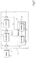
- the diagnostic method of the present invention starts with the acquisition of current values of the input temperature T I (block 100) and the output temperature T o (block 110).
- the current values acquired correspond to the measurements recorded by the input temperature sensor 12 and the output temperature sensor 8 and represented by the input temperature signal V I and the output temperature signal V o respectively.
- the real power P R is then calculated, in accordance with the equation (5) (block 120), so that the real heat Q R can then be obtained from equation (3) (block 130).
- the nominal power P N is then calculated on the basis of equation (2) (block 140) and the nominal heat Q NOM is then calculated according to (1) (block 150).
- An ageing index I given by the ratio between the real heat Q R and the nominal heat Q NOM and therefore representative of the state of ageing of the pre-catalyst 3, is then calculated (block 160).
- a test is then carried out to ascertain whether the ageing index I is lower than a predetermined threshold value I S (block 170). If so (output YES from the block 170) an error message is generated, setting the error signal E to a first logical value indicative of a malfunction (block 180) and the diagnostic algorithm is concluded (block 190). If not (output NO from the block 170) the diagnostic algorithm is terminated immediately after the performance of the test (block 190).
- a variant of the method described above is based on an exhaust gas purification system 1'', shown in Fig. 7, in which members identical to those already described with reference to Figs. 1 and 2 bear the same reference numerals.
- the system 1'' differs from the preceding systems since the first composition signal V 1 supplied by the first oxygen sensor 6 is supplied to an estimation block 15 forming part of the control unit 10.
- the estimation block 15 carries out an estimate of the input temperature T I as a function of the first composition signal V 1 and supplies it to a diagnostic block 16 which uses it to perform a diagnostic algorithm according to the variant of the present method.
- the above-mentioned estimation algorithm comprises obtaining the temperature of the exhaust gases at the input of the pre-catalyst via the measurement of the electrical power that it is necessary to supply to the heater present in the oxygen sensor to maintain the latter at a predetermined operating temperature.
- an estimation of this operating temperature is obtained from the measurement of the inner resistance of the sensor, the relationship between temperature and resistance being known, and is then compared with an objective temperature, obtaining a temperature error.
- the temperature error is supplied as input to a control unit, for instance a control unit with proportional-integral action, which supplies as output a control voltage in order to regulate the electrical power supplied to the heater.
- the estimated operating temperature and the control voltage whose effective value is an index of the electrical power supplied to the heater, are supplied as input to an estimation block which, on the basis of a mathematical model of heat exchange between the sensor, the heater and the exhaust gases in which the sensor is immersed, obtains an estimate of the temperature of the exhaust gases.
- the acquisition of a current value of the input temperature T I corresponds in particular to the performance of an estimation by the estimation block 15 and to the recording of the value supplied in this way.
- the diagnosis is not affected by the variations of the heating transient of the pre-catalyst 3 as a result of ageing is also advantageous.
- These effect of these variations may solely be to decrease of the real heat Q R supplied to the exhaust gases and therefore the comparison with the nominal heat Q NOM represents a robust criterion for evaluating whether the pre-catalyst 3 is operating correctly.
- a further advantage lies in the fact that the proposed solution is economic, since it requires the use of only one additional temperature sensor or even, in the case of the variant, the method may be implemented without having to include the use of new components.
Landscapes
- Engineering & Computer Science (AREA)
- Chemical & Material Sciences (AREA)
- Combustion & Propulsion (AREA)
- Mechanical Engineering (AREA)
- General Engineering & Computer Science (AREA)
- Chemical Kinetics & Catalysis (AREA)
- Exhaust Gas After Treatment (AREA)
- Testing Of Engines (AREA)
Applications Claiming Priority (2)
| Application Number | Priority Date | Filing Date | Title |
|---|---|---|---|
| ITBO990574 | 1999-10-26 | ||
| IT1999BO000574A IT1311110B1 (it) | 1999-10-26 | 1999-10-26 | Metodo per la diagnosi di un sistema di abbattimento dei gas discarico per un motore a combustione interna. |
Publications (2)
| Publication Number | Publication Date |
|---|---|
| EP1096117A1 true EP1096117A1 (fr) | 2001-05-02 |
| EP1096117B1 EP1096117B1 (fr) | 2003-04-16 |
Family
ID=11344304
Family Applications (1)
| Application Number | Title | Priority Date | Filing Date |
|---|---|---|---|
| EP00123147A Expired - Lifetime EP1096117B1 (fr) | 1999-10-26 | 2000-10-25 | Procédé de diagnostic d'un système de purification des gaz d'échappement pour moteur à combustion interne |
Country Status (6)
| Country | Link |
|---|---|
| US (1) | US6389805B1 (fr) |
| EP (1) | EP1096117B1 (fr) |
| BR (1) | BR0006735B1 (fr) |
| DE (1) | DE60002141T2 (fr) |
| ES (1) | ES2194664T3 (fr) |
| IT (1) | IT1311110B1 (fr) |
Cited By (2)
| Publication number | Priority date | Publication date | Assignee | Title |
|---|---|---|---|---|
| WO2010133276A1 (fr) * | 2009-05-21 | 2010-11-25 | Gm Global Technology Operations, Inc. | Procédé de calcul d'un indice de rendement de catalyseur à oxydation pour carburant diesel |
| CN102345494A (zh) * | 2010-04-28 | 2012-02-08 | 通用汽车环球科技运作有限责任公司 | 排气和部件温度估计系统和方法 |
Families Citing this family (7)
| Publication number | Priority date | Publication date | Assignee | Title |
|---|---|---|---|---|
| US6712054B2 (en) * | 2000-05-17 | 2004-03-30 | Unisia Jecs Corporation | Device and method for measuring element temperature of air-fuel ratio sensor, and device and method for controlling heater of air-fuel ratio sensor |
| DE10248842A1 (de) * | 2002-10-19 | 2004-04-29 | Daimlerchrysler Ag | Vorrichtung und Verfahren zur Bestimmung des Alterungszustands eines Abgaskatalysators |
| FR2860037B1 (fr) * | 2003-09-23 | 2006-02-24 | Peugeot Citroen Automobiles Sa | Procede et dispositif de determination de la temperature interne d'un catatlyseur de vehicule muni d'un moteur thermique |
| DE102004006992B4 (de) * | 2004-02-12 | 2013-05-29 | Volkswagen Ag | Diagnoseverfahren zum Bestimmen eines Zustandes eines Katalysatorsystems |
| US8549839B2 (en) * | 2010-04-28 | 2013-10-08 | GM Global Technology Operations LLC | Hydrocarbon energy storage and release control systems and methods |
| US8452518B2 (en) | 2010-04-28 | 2013-05-28 | GM Global Technology Operations LLC | Post-combustion fuel injection control systems and methods |
| DE102018218136B4 (de) * | 2018-10-23 | 2023-03-09 | Vitesco Technologies GmbH | Diagnoseverfahren für ein Abgasnachbehandlungssystem und Abgasnachbehandlungssystem |
Citations (4)
| Publication number | Priority date | Publication date | Assignee | Title |
|---|---|---|---|---|
| US5419122A (en) * | 1993-10-04 | 1995-05-30 | Ford Motor Company | Detection of catalytic converter operability by light-off time determination |
| EP0779416A1 (fr) * | 1995-12-15 | 1997-06-18 | Ngk Insulators, Ltd. | Méthode pour détecter une baisse de performance d'un catalyseur pour la purification de gaz d'échappement |
| US5647205A (en) * | 1993-03-19 | 1997-07-15 | Siemens Aktiengesellschaft | Process for checking the conversion capability of a catalyst |
| US5938715A (en) * | 1997-04-07 | 1999-08-17 | Siemens Aktiengesellschaft | Method for monitoring the conversion capacity of a catalytic converter |
Family Cites Families (5)
| Publication number | Priority date | Publication date | Assignee | Title |
|---|---|---|---|---|
| JP3244584B2 (ja) * | 1994-02-10 | 2002-01-07 | 株式会社日立製作所 | エンジン排気ガス浄化装置の診断方法及び装置 |
| JPH08338297A (ja) * | 1995-04-12 | 1996-12-24 | Toyota Motor Corp | 触媒劣化判定装置 |
| JP3603422B2 (ja) * | 1995-10-23 | 2004-12-22 | 日産自動車株式会社 | エンジンの触媒温度推定装置および触媒診断装置 |
| US5706652A (en) * | 1996-04-22 | 1998-01-13 | General Motors Corporation | Catalytic converter monitor method and apparatus |
| IT1310507B1 (it) | 1999-10-06 | 2002-02-18 | Magneti Marelli Spa | Metodo di stima della temperatura dei gas di scarico a monte di unprecatalizzatore disposto lungo un condotto di scarico di un motore a |
-
1999
- 1999-10-26 IT IT1999BO000574A patent/IT1311110B1/it active
-
2000
- 2000-10-20 BR BRPI0006735-0A patent/BR0006735B1/pt not_active IP Right Cessation
- 2000-10-25 EP EP00123147A patent/EP1096117B1/fr not_active Expired - Lifetime
- 2000-10-25 DE DE60002141T patent/DE60002141T2/de not_active Expired - Lifetime
- 2000-10-25 ES ES00123147T patent/ES2194664T3/es not_active Expired - Lifetime
- 2000-10-26 US US09/696,174 patent/US6389805B1/en not_active Expired - Fee Related
Patent Citations (4)
| Publication number | Priority date | Publication date | Assignee | Title |
|---|---|---|---|---|
| US5647205A (en) * | 1993-03-19 | 1997-07-15 | Siemens Aktiengesellschaft | Process for checking the conversion capability of a catalyst |
| US5419122A (en) * | 1993-10-04 | 1995-05-30 | Ford Motor Company | Detection of catalytic converter operability by light-off time determination |
| EP0779416A1 (fr) * | 1995-12-15 | 1997-06-18 | Ngk Insulators, Ltd. | Méthode pour détecter une baisse de performance d'un catalyseur pour la purification de gaz d'échappement |
| US5938715A (en) * | 1997-04-07 | 1999-08-17 | Siemens Aktiengesellschaft | Method for monitoring the conversion capacity of a catalytic converter |
Non-Patent Citations (1)
| Title |
|---|
| M. SIDERIS: "Methods for monitoring and diagnosing the efficiency of catalytic converters", 1998, ELSEVIER SCIENCE B.V., AMSTERDAM, XP002139547 * |
Cited By (4)
| Publication number | Priority date | Publication date | Assignee | Title |
|---|---|---|---|---|
| WO2010133276A1 (fr) * | 2009-05-21 | 2010-11-25 | Gm Global Technology Operations, Inc. | Procédé de calcul d'un indice de rendement de catalyseur à oxydation pour carburant diesel |
| US8621849B2 (en) | 2009-05-21 | 2014-01-07 | GM Global Technology Operations LLC | Method for diagnosing a diesel oxidation catalyst |
| CN102345494A (zh) * | 2010-04-28 | 2012-02-08 | 通用汽车环球科技运作有限责任公司 | 排气和部件温度估计系统和方法 |
| CN102345494B (zh) * | 2010-04-28 | 2014-12-17 | 通用汽车环球科技运作有限责任公司 | 排气和部件温度估计系统和方法 |
Also Published As
| Publication number | Publication date |
|---|---|
| BR0006735B1 (pt) | 2012-10-02 |
| ITBO990574A0 (it) | 1999-10-26 |
| EP1096117B1 (fr) | 2003-04-16 |
| IT1311110B1 (it) | 2002-02-28 |
| DE60002141T2 (de) | 2004-01-29 |
| ES2194664T3 (es) | 2003-12-01 |
| ITBO990574A1 (it) | 2001-04-26 |
| DE60002141D1 (de) | 2003-05-22 |
| BR0006735A (pt) | 2001-08-07 |
| US6389805B1 (en) | 2002-05-21 |
Similar Documents
| Publication | Publication Date | Title |
|---|---|---|
| US6202406B1 (en) | Method and apparatus for catalyst temperature control | |
| US7036982B2 (en) | Method and apparatus to control an exhaust gas sensor to a predetermined termperature | |
| US8276438B2 (en) | Method for verifying the aging condition of a catalytic converter on board a vehicle | |
| US20160265413A1 (en) | Method and device for monitoring a particulate filter | |
| US10550749B2 (en) | Exhaust gas temperature sensor diagnostic system | |
| US5177463A (en) | Method of and apparatus for monitoring operation of a catalytic converter | |
| US6401453B1 (en) | Method and device for monitoring the functional ability of a catalyst of an internal combustion engine | |
| JPH1181995A (ja) | 触媒モニタ | |
| CN108374712B (zh) | 用于借助于氨逸出在scr系统中进行故障识别的方法 | |
| EP1096117B1 (fr) | Procédé de diagnostic d'un système de purification des gaz d'échappement pour moteur à combustion interne | |
| US6964194B2 (en) | Device and method for determining the state of ageing of an exhaust-gas catalytic converter | |
| US5647205A (en) | Process for checking the conversion capability of a catalyst | |
| JPH09236569A (ja) | 内燃機関の排気浄化装置の機能診断装置 | |
| JPH1089134A (ja) | 内燃機関用炭化水素センサの機能のモニタ方法および装置 | |
| JP4329419B2 (ja) | ヒータ制御装置 | |
| US6314723B1 (en) | Method of checking the functional capability of a catalytic converter | |
| US20070277503A1 (en) | Method for checking the friction capability of an exhaust gas catalytic converter | |
| US5916294A (en) | System and method for estimating tailpipe a emissions in a vehicle | |
| US5941928A (en) | System and method for measuring hydrocarbon conversion efficiency of a catalytic converter | |
| JP2004251186A (ja) | 内燃機関の冷却水の温度センサの故障を診断する装置 | |
| US11852088B2 (en) | Method, computing unit, and computer program for determining an amount of hydrocarbons in an exhaust gas of a lean-operation internal-combustion engine | |
| US12241430B2 (en) | Method and device for diagnosing a heating element of an exhaust gas sensor of an internal combustion engine | |
| US7861519B2 (en) | Procedure to operate an exhaust gas treatment device and device to implement the procedure | |
| CN101245739A (zh) | 传感器激活监控 | |
| CN103237974B (zh) | 用于识别阶跃λ探测器的运行准备的方法 |
Legal Events
| Date | Code | Title | Description |
|---|---|---|---|
| PUAI | Public reference made under article 153(3) epc to a published international application that has entered the european phase |
Free format text: ORIGINAL CODE: 0009012 |
|
| AK | Designated contracting states |
Kind code of ref document: A1 Designated state(s): DE ES FR GB SE |
|
| AX | Request for extension of the european patent |
Free format text: AL;LT;LV;MK;RO;SI |
|
| 17P | Request for examination filed |
Effective date: 20010411 |
|
| 17Q | First examination report despatched |
Effective date: 20011205 |
|
| AKX | Designation fees paid |
Free format text: DE ES FR GB SE |
|
| GRAG | Despatch of communication of intention to grant |
Free format text: ORIGINAL CODE: EPIDOS AGRA |
|
| GRAG | Despatch of communication of intention to grant |
Free format text: ORIGINAL CODE: EPIDOS AGRA |
|
| GRAH | Despatch of communication of intention to grant a patent |
Free format text: ORIGINAL CODE: EPIDOS IGRA |
|
| RAP1 | Party data changed (applicant data changed or rights of an application transferred) |
Owner name: MAGNETI MARELLI POWERTRAIN S.P.A. |
|
| GRAH | Despatch of communication of intention to grant a patent |
Free format text: ORIGINAL CODE: EPIDOS IGRA |
|
| GRAA | (expected) grant |
Free format text: ORIGINAL CODE: 0009210 |
|
| AK | Designated contracting states |
Designated state(s): DE ES FR GB SE |
|
| REG | Reference to a national code |
Ref country code: GB Ref legal event code: FG4D |
|
| REF | Corresponds to: |
Ref document number: 60002141 Country of ref document: DE Date of ref document: 20030522 Kind code of ref document: P |
|
| REG | Reference to a national code |
Ref country code: SE Ref legal event code: TRGR |
|
| ET | Fr: translation filed | ||
| PLBE | No opposition filed within time limit |
Free format text: ORIGINAL CODE: 0009261 |
|
| STAA | Information on the status of an ep patent application or granted ep patent |
Free format text: STATUS: NO OPPOSITION FILED WITHIN TIME LIMIT |
|
| 26N | No opposition filed |
Effective date: 20040119 |
|
| PGFP | Annual fee paid to national office [announced via postgrant information from national office to epo] |
Ref country code: GB Payment date: 20090928 Year of fee payment: 10 Ref country code: SE Payment date: 20090924 Year of fee payment: 10 |
|
| PGFP | Annual fee paid to national office [announced via postgrant information from national office to epo] |
Ref country code: ES Payment date: 20091006 Year of fee payment: 10 |
|
| GBPC | Gb: european patent ceased through non-payment of renewal fee |
Effective date: 20101025 |
|
| PG25 | Lapsed in a contracting state [announced via postgrant information from national office to epo] |
Ref country code: GB Free format text: LAPSE BECAUSE OF NON-PAYMENT OF DUE FEES Effective date: 20101025 |
|
| PG25 | Lapsed in a contracting state [announced via postgrant information from national office to epo] |
Ref country code: SE Free format text: LAPSE BECAUSE OF NON-PAYMENT OF DUE FEES Effective date: 20101026 |
|
| REG | Reference to a national code |
Ref country code: ES Ref legal event code: FD2A Effective date: 20111118 |
|
| PG25 | Lapsed in a contracting state [announced via postgrant information from national office to epo] |
Ref country code: ES Free format text: LAPSE BECAUSE OF NON-PAYMENT OF DUE FEES Effective date: 20101026 |
|
| PGFP | Annual fee paid to national office [announced via postgrant information from national office to epo] |
Ref country code: FR Payment date: 20121115 Year of fee payment: 13 Ref country code: DE Payment date: 20120924 Year of fee payment: 13 |
|
| REG | Reference to a national code |
Ref country code: DE Ref legal event code: R119 Ref document number: 60002141 Country of ref document: DE Effective date: 20140501 |
|
| REG | Reference to a national code |
Ref country code: FR Ref legal event code: ST Effective date: 20140630 |
|
| PG25 | Lapsed in a contracting state [announced via postgrant information from national office to epo] |
Ref country code: DE Free format text: LAPSE BECAUSE OF NON-PAYMENT OF DUE FEES Effective date: 20140501 Ref country code: FR Free format text: LAPSE BECAUSE OF NON-PAYMENT OF DUE FEES Effective date: 20131031 |