EP1096175A2 - Actionneur linéaire - Google Patents
Actionneur linéaire Download PDFInfo
- Publication number
- EP1096175A2 EP1096175A2 EP00122830A EP00122830A EP1096175A2 EP 1096175 A2 EP1096175 A2 EP 1096175A2 EP 00122830 A EP00122830 A EP 00122830A EP 00122830 A EP00122830 A EP 00122830A EP 1096175 A2 EP1096175 A2 EP 1096175A2
- Authority
- EP
- European Patent Office
- Prior art keywords
- spindle
- support
- output shaft
- drive
- linear
- Prior art date
- Legal status (The legal status is an assumption and is not a legal conclusion. Google has not performed a legal analysis and makes no representation as to the accuracy of the status listed.)
- Withdrawn
Links
- 230000007246 mechanism Effects 0.000 claims abstract description 49
- 238000006243 chemical reaction Methods 0.000 claims description 9
- 230000033001 locomotion Effects 0.000 claims description 5
- 230000010355 oscillation Effects 0.000 claims description 2
- 230000008878 coupling Effects 0.000 claims 1
- 238000010168 coupling process Methods 0.000 claims 1
- 238000005859 coupling reaction Methods 0.000 claims 1
- 238000005452 bending Methods 0.000 description 4
- 238000000034 method Methods 0.000 description 4
- XAGFODPZIPBFFR-UHFFFAOYSA-N aluminium Chemical compound [Al] XAGFODPZIPBFFR-UHFFFAOYSA-N 0.000 description 2
- 229910052782 aluminium Inorganic materials 0.000 description 2
- 230000000694 effects Effects 0.000 description 2
- 229910000831 Steel Inorganic materials 0.000 description 1
- 230000005540 biological transmission Effects 0.000 description 1
- 238000010276 construction Methods 0.000 description 1
- 230000001419 dependent effect Effects 0.000 description 1
- 239000000428 dust Substances 0.000 description 1
- 239000000463 material Substances 0.000 description 1
- 238000010187 selection method Methods 0.000 description 1
- 239000010959 steel Substances 0.000 description 1
- 210000001562 sternum Anatomy 0.000 description 1
- 230000003319 supportive effect Effects 0.000 description 1
- XLYOFNOQVPJJNP-UHFFFAOYSA-N water Substances O XLYOFNOQVPJJNP-UHFFFAOYSA-N 0.000 description 1
Images


Classifications
-
- F—MECHANICAL ENGINEERING; LIGHTING; HEATING; WEAPONS; BLASTING
- F16—ENGINEERING ELEMENTS AND UNITS; GENERAL MEASURES FOR PRODUCING AND MAINTAINING EFFECTIVE FUNCTIONING OF MACHINES OR INSTALLATIONS; THERMAL INSULATION IN GENERAL
- F16H—GEARING
- F16H25/00—Gearings comprising primarily only cams, cam-followers and screw-and-nut mechanisms
- F16H25/18—Gearings comprising primarily only cams, cam-followers and screw-and-nut mechanisms for conveying or interconverting oscillating or reciprocating motions
- F16H25/20—Screw mechanisms
-
- H—ELECTRICITY
- H02—GENERATION; CONVERSION OR DISTRIBUTION OF ELECTRIC POWER
- H02K—DYNAMO-ELECTRIC MACHINES
- H02K7/00—Arrangements for handling mechanical energy structurally associated with dynamo-electric machines, e.g. structural association with mechanical driving motors or auxiliary dynamo-electric machines
- H02K7/06—Means for converting reciprocating motion into rotary motion or vice versa
-
- F—MECHANICAL ENGINEERING; LIGHTING; HEATING; WEAPONS; BLASTING
- F16—ENGINEERING ELEMENTS AND UNITS; GENERAL MEASURES FOR PRODUCING AND MAINTAINING EFFECTIVE FUNCTIONING OF MACHINES OR INSTALLATIONS; THERMAL INSULATION IN GENERAL
- F16H—GEARING
- F16H25/00—Gearings comprising primarily only cams, cam-followers and screw-and-nut mechanisms
- F16H25/18—Gearings comprising primarily only cams, cam-followers and screw-and-nut mechanisms for conveying or interconverting oscillating or reciprocating motions
- F16H25/20—Screw mechanisms
- F16H2025/2062—Arrangements for driving the actuator
- F16H2025/2075—Coaxial drive motors
-
- Y—GENERAL TAGGING OF NEW TECHNOLOGICAL DEVELOPMENTS; GENERAL TAGGING OF CROSS-SECTIONAL TECHNOLOGIES SPANNING OVER SEVERAL SECTIONS OF THE IPC; TECHNICAL SUBJECTS COVERED BY FORMER USPC CROSS-REFERENCE ART COLLECTIONS [XRACs] AND DIGESTS
- Y10—TECHNICAL SUBJECTS COVERED BY FORMER USPC
- Y10T—TECHNICAL SUBJECTS COVERED BY FORMER US CLASSIFICATION
- Y10T74/00—Machine element or mechanism
- Y10T74/18—Mechanical movements
- Y10T74/18568—Reciprocating or oscillating to or from alternating rotary
- Y10T74/18576—Reciprocating or oscillating to or from alternating rotary including screw and nut
- Y10T74/18656—Carriage surrounded, guided, and primarily supported by member other than screw [e.g., linear guide, etc.]
-
- Y—GENERAL TAGGING OF NEW TECHNOLOGICAL DEVELOPMENTS; GENERAL TAGGING OF CROSS-SECTIONAL TECHNOLOGIES SPANNING OVER SEVERAL SECTIONS OF THE IPC; TECHNICAL SUBJECTS COVERED BY FORMER USPC CROSS-REFERENCE ART COLLECTIONS [XRACs] AND DIGESTS
- Y10—TECHNICAL SUBJECTS COVERED BY FORMER USPC
- Y10T—TECHNICAL SUBJECTS COVERED BY FORMER US CLASSIFICATION
- Y10T74/00—Machine element or mechanism
- Y10T74/18—Mechanical movements
- Y10T74/18568—Reciprocating or oscillating to or from alternating rotary
- Y10T74/18576—Reciprocating or oscillating to or from alternating rotary including screw and nut
- Y10T74/1868—Deflection related
Definitions
- the present invention relates to a linear drive a movement conversion mechanism from rotation Linear motion.
- linear actuators have been taking electrical Engines too.
- the motor turns a screw or spindle, like a ball spindle etc., and one coupled to the spindle Nut or nut moves linearly, so accordingly an output shaft connected to the nut itself moved linearly.
- This type of linear actuator is located the engine is mainly on a support block that supports the Spindle supported in the direction of the spindle axis and itself located on the other side of the output shaft.
- the Clevis mechanism becomes one of the cylinders Vibration support mechanisms are used to assist the distal end of the cylinder from the output shaft to be positioned. If for the linear drive with an electric motor the same type of Clevis mechanism positioning should be used Clevis mechanism positioned approximately at the end of the engine become. However, the engine is generally not force-bearing part that is designed to be strong enough to able to respond to the output shaft to be carried by an actuated load. So everyone should Part of the Clevis mechanism on the side of the engine end his. In fact, linear actuators are electric powered engine generally does not use the Clevis mechanism fitted. Such are accordingly Linear drives with an electrically driven motor in the Generally not with a trunnion mechanism either fitted.
- Vibration support mechanism such as the trunnion mechanism or Clevis mechanism, inevitable.
- the effect of the invention is based on the fact that in the electrically operated linear drive the spindle is used to be supported by bearings or by bearings in the radial or axial direction, so that the spindle can rotate, the axis remaining stable and does not move in the axial direction by a reaction force from an actuated load applied by the output shaft and the nut to the spindle.
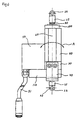
- Figures 1 and 2 show an example corresponding to the Invention of a first embodiment of a linear drive with an electrically operated motor that is controlled by a Trunnion mechanism is supported as one of the Vibration support mechanisms.
- a screw or spindle 60 is supported by a support block 30 supports so that the spindle 60 is not in Moves in the direction of a spindle axis 69, but in the Spindle axis using two angled bearings 31 (one is 31a and the other is 31b) rotates.
- the bearings 31 are held in the support block 30, hold a crown part 61a at an end portion 61 of the spindle 60, and on the support block 30 fastened by a bearing nut 32.
- a motor 40 is screwed to the support block 30 attached, with a motor axis 41 in an opening the end piece 61 of the spindle is inserted, and by attached a set of screws, which is not in Figure 1 is shown.
- the spindle 60 is a so-called ball spindle, and one Nut or nut 70 couples to the spindle 60.
- the nut has two pins 71 with a guide recess 91st couple, which is carried out on a cylinder cover 90 and is parallel to the screw axis 69. Accordingly, the nut 70 moves linearly in Corresponds to a rotation of the spindle 60.
- An output shaft 80 is connected to the nut 70 and is guided by a bearing 101 that in an end cover 100 is held.
- the engine 40 is covered by an engine cover 50, to keep dust and water out.
- An electric one Wiring for driving the motor can go inside the engine cover 50 are guided.
- a swing axis 11 of a trunnion mechanism is provided to meet the condition on the support block 30 "and on the plane containing the spindle axis 69 "as the drive side support member. This satisfies the conditions that no bending torque as shown by an arrow A results from any part of the drive when the output shaft 80 actuates the load and carries a reaction force. This therefore represents the best and ideal way to support the drive in such a way that the support block 30 plays the role of the support part of the drive.
- the swing axis on the extended part the support block 30 attached to the support block 30 can be offered.
- the supportive effect is the same as described above.
- Figures 3 and 4 show an example of another Embodiment according to the present invention, the one Has linear drive with an electric motor, the is supported by a Clevis mechanism that is also one of the vibration support mechanisms.
- An arm portion 20 of the Clevis mechanism is listed that has a portion 21, wherein a bearing recess with a Swing axis 22 is provided.
- the arm part plays the role of the portion 21 with the support block 30 to connect and is attached to the support block by means of screws attached.
- the swing axis 22 is here in the Provided spindle axis 69 level.
- the support block 30 for the purpose of Strength preferably made of steel. Thick Aluminum can also be used.
- the engine cover 50 and the cylinder cover 90 are for the purpose of light weight, preferably thin Made of aluminum. Plastic materials can also be used for be used for the same purpose.
- Figures 3 and 4 show another type of Output shaft 80 actuating end.
- This type of Output shaft 80 is more effective together with the support methods of this invention.
- On Actuating end 25 is located with a bearing recess 26 itself at the end of the output shaft 80, and the center line the bearing recess 26 is in the plane that the Center line of the bearing recess 23 and the spindle axis 69 includes.
- the output shaft 80 can be the thinnest Dimension in combination with the Support method of this invention and the Actuation end 25.
- Figures 5 and 6 show further examples of the Combination between the drive and the Support method of this invention.
- the drive motor is turned 180 degrees, and the The length of the drive is shortened.
Landscapes
- Engineering & Computer Science (AREA)
- General Engineering & Computer Science (AREA)
- Power Engineering (AREA)
- Mechanical Engineering (AREA)
- Transmission Devices (AREA)
- Connection Of Motors, Electrical Generators, Mechanical Devices, And The Like (AREA)
Applications Claiming Priority (2)
| Application Number | Priority Date | Filing Date | Title |
|---|---|---|---|
| JP30476999 | 1999-10-27 | ||
| JP30476999A JP2001124170A (ja) | 1999-10-27 | 1999-10-27 | リニアアクチュエータの支持点設置方式 |
Publications (2)
| Publication Number | Publication Date |
|---|---|
| EP1096175A2 true EP1096175A2 (fr) | 2001-05-02 |
| EP1096175A3 EP1096175A3 (fr) | 2004-01-28 |
Family
ID=17937012
Family Applications (1)
| Application Number | Title | Priority Date | Filing Date |
|---|---|---|---|
| EP00122830A Withdrawn EP1096175A3 (fr) | 1999-10-27 | 2000-10-20 | Actionneur linéaire |
Country Status (3)
| Country | Link |
|---|---|
| US (1) | US6619147B1 (fr) |
| EP (1) | EP1096175A3 (fr) |
| JP (1) | JP2001124170A (fr) |
Cited By (2)
| Publication number | Priority date | Publication date | Assignee | Title |
|---|---|---|---|---|
| EP1661846A3 (fr) * | 2004-11-17 | 2007-05-09 | Jürgen Zimmermann | Actionneur |
| DE102006026478B4 (de) * | 2005-06-08 | 2017-10-19 | Koito Manufacturing Co., Ltd. | Fahrzeugscheinwerfer |
Families Citing this family (14)
| Publication number | Priority date | Publication date | Assignee | Title |
|---|---|---|---|---|
| JP2003170381A (ja) * | 2001-11-30 | 2003-06-17 | Seiko Epson Corp | 操作装置 |
| WO2006133479A1 (fr) * | 2005-06-15 | 2006-12-21 | Razorback Vehicles Corporation Limited | Cylindre pneumatique ou hydraulique |
| TWM288913U (en) * | 2005-09-16 | 2006-03-21 | Tricore Corp | Linear actuator with stepping motor |
| US7748308B2 (en) * | 2005-09-26 | 2010-07-06 | Unico, Inc. | Pneumatic biasing of a linear actuator and implementations thereof |
| EP1840311A1 (fr) * | 2006-03-31 | 2007-10-03 | Valeo Sicherheitssysteme GmbH | Mécanisme de reglage a broche linéaire |
| US20070295128A1 (en) * | 2006-05-19 | 2007-12-27 | Erikson Keith W | Lead screw actuator with torsional anti-backlash nut |
| US7891265B2 (en) * | 2006-11-16 | 2011-02-22 | Haydon Kerk Motion Solutions, Inc. | Motor assembly with anti-backlash nut and thermal insensitive mechanism |
| US8079578B2 (en) * | 2007-09-05 | 2011-12-20 | Hgs Aerospace, Inc. | Universal holding fixture |
| US20090249910A1 (en) * | 2008-04-04 | 2009-10-08 | Kerk Motion Products, Inc. | Lead screw device |
| EP2199513B1 (fr) * | 2008-12-19 | 2013-05-01 | Valeo Sicherheitssysteme GmbH | Actionneur avec entraînement à vis et écrou |
| JP5427647B2 (ja) * | 2010-03-01 | 2014-02-26 | Ckd株式会社 | 電動アクチュエータ |
| JP5648997B2 (ja) * | 2010-09-16 | 2015-01-07 | カヤバ工業株式会社 | リニアアクチュエータ |
| JP5914031B2 (ja) * | 2012-02-17 | 2016-05-11 | Ntn株式会社 | 電動リニアアクチュエータ |
| US9689251B2 (en) | 2014-05-08 | 2017-06-27 | Unico, Inc. | Subterranean pump with pump cleaning mode |
Family Cites Families (9)
| Publication number | Priority date | Publication date | Assignee | Title |
|---|---|---|---|---|
| US2320953A (en) * | 1941-04-25 | 1943-06-01 | Massey Harris Co Ltd | Electric power lift |
| US2459982A (en) * | 1944-12-13 | 1949-01-25 | Boeing Co | Retractable shock absorbing strut |
| US2562689A (en) * | 1948-06-21 | 1951-07-31 | Earl Hovey C | Screw and nut transmission |
| US2682780A (en) * | 1953-02-11 | 1954-07-06 | Hupp Corp | Convertible top lift actuator |
| US2769430A (en) * | 1953-08-31 | 1956-11-06 | Gen Motors Corp | Actuator with dual locking means |
| US3682283A (en) * | 1970-03-02 | 1972-08-08 | Mitumasa Sato | Motor-driven actuator and safety overload mechanism therefor |
| US3798983A (en) * | 1972-05-15 | 1974-03-26 | W Smith | Adaptable gear housing for linear actuator construction |
| US4307799A (en) * | 1979-12-05 | 1981-12-29 | Andco Actuator Products, Inc. | Linear actuator |
| US4858481A (en) * | 1985-05-13 | 1989-08-22 | Brunswick Valve & Control, Inc. | Position controlled linear actuator |
-
1999
- 1999-10-27 JP JP30476999A patent/JP2001124170A/ja active Pending
-
2000
- 2000-10-20 EP EP00122830A patent/EP1096175A3/fr not_active Withdrawn
- 2000-10-26 US US09/697,254 patent/US6619147B1/en not_active Expired - Fee Related
Non-Patent Citations (1)
| Title |
|---|
| None |
Cited By (2)
| Publication number | Priority date | Publication date | Assignee | Title |
|---|---|---|---|---|
| EP1661846A3 (fr) * | 2004-11-17 | 2007-05-09 | Jürgen Zimmermann | Actionneur |
| DE102006026478B4 (de) * | 2005-06-08 | 2017-10-19 | Koito Manufacturing Co., Ltd. | Fahrzeugscheinwerfer |
Also Published As
| Publication number | Publication date |
|---|---|
| US6619147B1 (en) | 2003-09-16 |
| JP2001124170A (ja) | 2001-05-08 |
| EP1096175A3 (fr) | 2004-01-28 |
Similar Documents
| Publication | Publication Date | Title |
|---|---|---|
| EP1096175A2 (fr) | Actionneur linéaire | |
| DE3416938C2 (de) | Von einem Elektromotor angetriebenes, eine Längsbewegung ausführendes Stellglied | |
| DE60012616T2 (de) | Elektrische und mechanische Kraftfahrzeuglenkeinrichtung | |
| DE202015006083U1 (de) | Hubwindenanordnung | |
| CH666728A5 (de) | Rotor einer windkraftanlage. | |
| DE112021006252T5 (de) | Fahrzeughöheneinstellvorrichtung | |
| EP2187097A1 (fr) | Entraînement linéaire | |
| DE102023120475B4 (de) | Antriebsvorrichtung für einen Roboter sowie Roboter mit einer solchen Antriebsvorrichtung | |
| DE69908873T2 (de) | Rotorblatt, insbesondere für einen heckrotor eines hubschraubers | |
| EP0785129B1 (fr) | Propulseur cycloidal, notamment pour propulsion de bateaux | |
| DE4002791C2 (de) | Antriebsanlage für ein Fahrzeug, insbesondere für ein Vollkettenfahrzeug | |
| DE102009029877A1 (de) | Torquemotor mit Brems- und/oder Halteeinrichtung | |
| EP4339059A1 (fr) | Attelage central pour véhicule ferroviaire et véhicule ferroviaire doté d'un tel attelage central | |
| DE69114688T2 (de) | Industrieroboter mit mehrfachem antrieb. | |
| DE2025621A1 (de) | Elektromotorisch angetriebenes Werkzeug | |
| EP3523160A1 (fr) | Ensemble transmission pour un entraînement à broche, entraînement à broche et siège de véhicule | |
| DE711124C (de) | Einrichtung zum Antrieb von Walzen, insbesondere Walzen fuer Papiermaschinen | |
| DE10234738A1 (de) | Aktuator | |
| DE4217128A1 (de) | Deckenversorgungseinheit | |
| DE2810970C3 (de) | Hydrostatische Hilfskraftlenkeinrichtung für Fahrzeuge | |
| EP4303466B1 (fr) | Actionneur linéaire électromécanique doté d'un moteur à arbre creux | |
| DE102024209979B3 (de) | Drehbare Patientenliege für RT-Anwendungen | |
| DE102023121376B4 (de) | Verbinder, Linearantrieb, Lenksystem sowie Fahrzeug | |
| DE2300812A1 (de) | Faltpropeller fuer segeljachten mit hilfsmotor | |
| DE69018433T2 (de) | Rettungswerkzeug mit Schraubantrieb. |
Legal Events
| Date | Code | Title | Description |
|---|---|---|---|
| PUAI | Public reference made under article 153(3) epc to a published international application that has entered the european phase |
Free format text: ORIGINAL CODE: 0009012 |
|
| AK | Designated contracting states |
Kind code of ref document: A2 Designated state(s): AT BE CH CY DE DK ES FI FR GB GR IE IT LI LU MC NL PT SE |
|
| AX | Request for extension of the european patent |
Free format text: AL;LT;LV;MK;RO;SI |
|
| RAP1 | Party data changed (applicant data changed or rights of an application transferred) |
Owner name: WITTENSTEIN GMBH & CO. KG |
|
| RAP1 | Party data changed (applicant data changed or rights of an application transferred) |
Owner name: WITTENSTEIN AG |
|
| PUAL | Search report despatched |
Free format text: ORIGINAL CODE: 0009013 |
|
| AK | Designated contracting states |
Kind code of ref document: A3 Designated state(s): AT BE CH CY DE DK ES FI FR GB GR IE IT LI LU MC NL PT SE |
|
| AX | Request for extension of the european patent |
Extension state: AL LT LV MK RO SI |
|
| 17P | Request for examination filed |
Effective date: 20040211 |
|
| AKX | Designation fees paid |
Designated state(s): AT BE CH CY DE DK ES FI FR GB GR IE IT LI LU MC NL PT SE |
|
| STAA | Information on the status of an ep patent application or granted ep patent |
Free format text: STATUS: THE APPLICATION IS DEEMED TO BE WITHDRAWN |
|
| 18D | Application deemed to be withdrawn |
Effective date: 20080501 |