EP1096178A2 - Dispositif et méthode de commande de changement de vitesse pour transmission automatique - Google Patents
Dispositif et méthode de commande de changement de vitesse pour transmission automatique Download PDFInfo
- Publication number
- EP1096178A2 EP1096178A2 EP99126175A EP99126175A EP1096178A2 EP 1096178 A2 EP1096178 A2 EP 1096178A2 EP 99126175 A EP99126175 A EP 99126175A EP 99126175 A EP99126175 A EP 99126175A EP 1096178 A2 EP1096178 A2 EP 1096178A2
- Authority
- EP
- European Patent Office
- Prior art keywords
- speed
- engagement
- engagement element
- shifting
- hydraulic pressure
- Prior art date
- Legal status (The legal status is an assumption and is not a legal conclusion. Google has not performed a legal analysis and makes no representation as to the accuracy of the status listed.)
- Granted
Links
- 230000005540 biological transmission Effects 0.000 title claims abstract description 59
- 238000000034 method Methods 0.000 title claims description 13
- 230000004913 activation Effects 0.000 claims abstract description 17
- 230000001133 acceleration Effects 0.000 claims description 7
- 230000003247 decreasing effect Effects 0.000 claims description 5
- XDDAORKBJWWYJS-UHFFFAOYSA-N glyphosate Chemical compound OC(=O)CNCP(O)(O)=O XDDAORKBJWWYJS-UHFFFAOYSA-N 0.000 claims description 3
- 230000003213 activating effect Effects 0.000 claims 2
- 230000008859 change Effects 0.000 abstract description 21
- 230000035939 shock Effects 0.000 abstract description 12
- 238000012545 processing Methods 0.000 description 20
- 238000010276 construction Methods 0.000 description 11
- 230000007246 mechanism Effects 0.000 description 7
- 230000002441 reversible effect Effects 0.000 description 7
- 238000010586 diagram Methods 0.000 description 6
- 239000006185 dispersion Substances 0.000 description 5
- 230000001052 transient effect Effects 0.000 description 4
- 230000009467 reduction Effects 0.000 description 3
- 230000004044 response Effects 0.000 description 3
- 230000032683 aging Effects 0.000 description 2
- 230000008901 benefit Effects 0.000 description 2
- 230000007423 decrease Effects 0.000 description 2
- 230000003111 delayed effect Effects 0.000 description 2
- 238000012544 monitoring process Methods 0.000 description 2
- 231100000681 Certain safety factor Toxicity 0.000 description 1
- 230000006399 behavior Effects 0.000 description 1
- 230000000593 degrading effect Effects 0.000 description 1
- 230000001419 dependent effect Effects 0.000 description 1
- 238000011161 development Methods 0.000 description 1
- 230000018109 developmental process Effects 0.000 description 1
- 230000000694 effects Effects 0.000 description 1
- 238000005265 energy consumption Methods 0.000 description 1
- 238000005516 engineering process Methods 0.000 description 1
- 230000007717 exclusion Effects 0.000 description 1
- 238000002474 experimental method Methods 0.000 description 1
- 239000000446 fuel Substances 0.000 description 1
- 230000006870 function Effects 0.000 description 1
- 238000009499 grossing Methods 0.000 description 1
- 238000009434 installation Methods 0.000 description 1
- 238000009877 rendering Methods 0.000 description 1
Images


Classifications
-
- F—MECHANICAL ENGINEERING; LIGHTING; HEATING; WEAPONS; BLASTING
- F16—ENGINEERING ELEMENTS AND UNITS; GENERAL MEASURES FOR PRODUCING AND MAINTAINING EFFECTIVE FUNCTIONING OF MACHINES OR INSTALLATIONS; THERMAL INSULATION IN GENERAL
- F16H—GEARING
- F16H61/00—Control functions within control units of change-speed- or reversing-gearings for conveying rotary motion ; Control of exclusively fluid gearing, friction gearing, gearings with endless flexible members or other particular types of gearing
- F16H61/04—Smoothing ratio shift
- F16H61/0437—Smoothing ratio shift by using electrical signals
-
- F—MECHANICAL ENGINEERING; LIGHTING; HEATING; WEAPONS; BLASTING
- F16—ENGINEERING ELEMENTS AND UNITS; GENERAL MEASURES FOR PRODUCING AND MAINTAINING EFFECTIVE FUNCTIONING OF MACHINES OR INSTALLATIONS; THERMAL INSULATION IN GENERAL
- F16H—GEARING
- F16H59/00—Control inputs to control units of change-speed- or reversing-gearings for conveying rotary motion
- F16H59/68—Inputs being a function of gearing status
- F16H2059/6807—Status of gear-change operation, e.g. clutch fully engaged
-
- F—MECHANICAL ENGINEERING; LIGHTING; HEATING; WEAPONS; BLASTING
- F16—ENGINEERING ELEMENTS AND UNITS; GENERAL MEASURES FOR PRODUCING AND MAINTAINING EFFECTIVE FUNCTIONING OF MACHINES OR INSTALLATIONS; THERMAL INSULATION IN GENERAL
- F16H—GEARING
- F16H61/00—Control functions within control units of change-speed- or reversing-gearings for conveying rotary motion ; Control of exclusively fluid gearing, friction gearing, gearings with endless flexible members or other particular types of gearing
- F16H61/04—Smoothing ratio shift
- F16H2061/0444—Smoothing ratio shift during fast shifting over two gearsteps, e.g. jumping from fourth to second gear
-
- F—MECHANICAL ENGINEERING; LIGHTING; HEATING; WEAPONS; BLASTING
- F16—ENGINEERING ELEMENTS AND UNITS; GENERAL MEASURES FOR PRODUCING AND MAINTAINING EFFECTIVE FUNCTIONING OF MACHINES OR INSTALLATIONS; THERMAL INSULATION IN GENERAL
- F16H—GEARING
- F16H61/00—Control functions within control units of change-speed- or reversing-gearings for conveying rotary motion ; Control of exclusively fluid gearing, friction gearing, gearings with endless flexible members or other particular types of gearing
- F16H61/04—Smoothing ratio shift
- F16H2061/0451—Smoothing ratio shift during swap-shifts, i.e. gear shifts between different planetary units, e.g. with double transitions shift involving three or more friction members
-
- F—MECHANICAL ENGINEERING; LIGHTING; HEATING; WEAPONS; BLASTING
- F16—ENGINEERING ELEMENTS AND UNITS; GENERAL MEASURES FOR PRODUCING AND MAINTAINING EFFECTIVE FUNCTIONING OF MACHINES OR INSTALLATIONS; THERMAL INSULATION IN GENERAL
- F16H—GEARING
- F16H61/00—Control functions within control units of change-speed- or reversing-gearings for conveying rotary motion ; Control of exclusively fluid gearing, friction gearing, gearings with endless flexible members or other particular types of gearing
- F16H61/04—Smoothing ratio shift
- F16H2061/0455—Smoothing ratio shift during shifts involving three or more shift members, e.g. release of 3-4 clutch, 2-4 brake and apply of forward clutch C1
-
- F—MECHANICAL ENGINEERING; LIGHTING; HEATING; WEAPONS; BLASTING
- F16—ENGINEERING ELEMENTS AND UNITS; GENERAL MEASURES FOR PRODUCING AND MAINTAINING EFFECTIVE FUNCTIONING OF MACHINES OR INSTALLATIONS; THERMAL INSULATION IN GENERAL
- F16H—GEARING
- F16H2200/00—Transmissions for multiple ratios
- F16H2200/20—Transmissions using gears with orbital motion
- F16H2200/2097—Transmissions using gears with orbital motion comprising an orbital gear set member permanently connected to the housing, e.g. a sun wheel permanently connected to the housing
-
- F—MECHANICAL ENGINEERING; LIGHTING; HEATING; WEAPONS; BLASTING
- F16—ENGINEERING ELEMENTS AND UNITS; GENERAL MEASURES FOR PRODUCING AND MAINTAINING EFFECTIVE FUNCTIONING OF MACHINES OR INSTALLATIONS; THERMAL INSULATION IN GENERAL
- F16H—GEARING
- F16H59/00—Control inputs to control units of change-speed- or reversing-gearings for conveying rotary motion
- F16H59/36—Inputs being a function of speed
- F16H59/46—Inputs being a function of speed dependent on a comparison between speeds
-
- F—MECHANICAL ENGINEERING; LIGHTING; HEATING; WEAPONS; BLASTING
- F16—ENGINEERING ELEMENTS AND UNITS; GENERAL MEASURES FOR PRODUCING AND MAINTAINING EFFECTIVE FUNCTIONING OF MACHINES OR INSTALLATIONS; THERMAL INSULATION IN GENERAL
- F16H—GEARING
- F16H61/00—Control functions within control units of change-speed- or reversing-gearings for conveying rotary motion ; Control of exclusively fluid gearing, friction gearing, gearings with endless flexible members or other particular types of gearing
- F16H61/02—Control functions within control units of change-speed- or reversing-gearings for conveying rotary motion ; Control of exclusively fluid gearing, friction gearing, gearings with endless flexible members or other particular types of gearing characterised by the signals used
- F16H61/0202—Control functions within control units of change-speed- or reversing-gearings for conveying rotary motion ; Control of exclusively fluid gearing, friction gearing, gearings with endless flexible members or other particular types of gearing characterised by the signals used the signals being electric
- F16H61/0204—Control functions within control units of change-speed- or reversing-gearings for conveying rotary motion ; Control of exclusively fluid gearing, friction gearing, gearings with endless flexible members or other particular types of gearing characterised by the signals used the signals being electric for gearshift control, e.g. control functions for performing shifting or generation of shift signal
- F16H61/0213—Control functions within control units of change-speed- or reversing-gearings for conveying rotary motion ; Control of exclusively fluid gearing, friction gearing, gearings with endless flexible members or other particular types of gearing characterised by the signals used the signals being electric for gearshift control, e.g. control functions for performing shifting or generation of shift signal characterised by the method for generating shift signals
-
- F—MECHANICAL ENGINEERING; LIGHTING; HEATING; WEAPONS; BLASTING
- F16—ENGINEERING ELEMENTS AND UNITS; GENERAL MEASURES FOR PRODUCING AND MAINTAINING EFFECTIVE FUNCTIONING OF MACHINES OR INSTALLATIONS; THERMAL INSULATION IN GENERAL
- F16H—GEARING
- F16H61/00—Control functions within control units of change-speed- or reversing-gearings for conveying rotary motion ; Control of exclusively fluid gearing, friction gearing, gearings with endless flexible members or other particular types of gearing
- F16H61/04—Smoothing ratio shift
- F16H61/06—Smoothing ratio shift by controlling rate of change of fluid pressure
- F16H61/061—Smoothing ratio shift by controlling rate of change of fluid pressure using electric control means
-
- F—MECHANICAL ENGINEERING; LIGHTING; HEATING; WEAPONS; BLASTING
- F16—ENGINEERING ELEMENTS AND UNITS; GENERAL MEASURES FOR PRODUCING AND MAINTAINING EFFECTIVE FUNCTIONING OF MACHINES OR INSTALLATIONS; THERMAL INSULATION IN GENERAL
- F16H—GEARING
- F16H61/00—Control functions within control units of change-speed- or reversing-gearings for conveying rotary motion ; Control of exclusively fluid gearing, friction gearing, gearings with endless flexible members or other particular types of gearing
- F16H61/04—Smoothing ratio shift
- F16H61/08—Timing control
-
- F—MECHANICAL ENGINEERING; LIGHTING; HEATING; WEAPONS; BLASTING
- F16—ENGINEERING ELEMENTS AND UNITS; GENERAL MEASURES FOR PRODUCING AND MAINTAINING EFFECTIVE FUNCTIONING OF MACHINES OR INSTALLATIONS; THERMAL INSULATION IN GENERAL
- F16H—GEARING
- F16H61/00—Control functions within control units of change-speed- or reversing-gearings for conveying rotary motion ; Control of exclusively fluid gearing, friction gearing, gearings with endless flexible members or other particular types of gearing
- F16H61/68—Control functions within control units of change-speed- or reversing-gearings for conveying rotary motion ; Control of exclusively fluid gearing, friction gearing, gearings with endless flexible members or other particular types of gearing specially adapted for stepped gearings
- F16H61/684—Control functions within control units of change-speed- or reversing-gearings for conveying rotary motion ; Control of exclusively fluid gearing, friction gearing, gearings with endless flexible members or other particular types of gearing specially adapted for stepped gearings without interruption of drive
- F16H61/686—Control functions within control units of change-speed- or reversing-gearings for conveying rotary motion ; Control of exclusively fluid gearing, friction gearing, gearings with endless flexible members or other particular types of gearing specially adapted for stepped gearings without interruption of drive with orbital gears
Definitions
- the present invention relates to a shift control apparatus for an automatic transmission according to the preamble of claim 1 and to a shift control method according to the preamble of claim 26.
- the present invention relates to a technique for smoothly performing shift requiring disengagement and engagement of two different engagement elements between shift stages (simultaneous grip change of four elements).
- engagement elements for up-shift and down-shift basically includes additional engagement of another engagement element or disengagement of at least one engagement element being engaged. If the aforementioned operation cannot be performed because of the gear train construction, one engagement element that has been already engaged is disengaged so as to engage another engagement element, that is, performing so called grip change operation of engagement elements.
- an automatic transmission has been increasingly employed a multi-stage shifting mechanism so as to improve drivability and reduce the fuel cost for decreasing energy consumption.
- Such multi-stage shifting has been generally achieved by adding an acceleration or deceleration stage using an overdrive or under-drive gear to a shift mechanism consisting of a multi-staged planetary gear set.
- EP-0434525B1 as generic prior art a technology for achieving multi-stages by employing an input to Ravigneaux type of planetary gear set as two systems of high/low to achieve multi-stages.
- the shifting speed conforming to the running state of a vehicle can be selected from a wider range of choices, thus causing the requirement for complicated grip change of four elements as well as simple grip change of two elements.
- a so-called skip shift from a number of shift stages to a particular shift stage at one time.
- how to control sequence or timing of engagement and disengagement of each engagement element becomes a key issue.
- the failure of this control if any, may cause the problem of degrading smooth advancement of shift operatedwiththetransmissionmechanism.
- shift continuity is lost, there is another problem of causing stepwise shocks during shifting, worsening of shocks at the end of shifting or an necessary increase of a shifting.
- the shift control apparatus for automatic transmission is capable of preventing retardation of shifting while minimizing shock during shifting by smoothing the advancing shift that requires engagement and disengagement of four engagement elements.
- the automatic transmission has brakes, clutches and /or one-way-clutches as engaging elements.
- disengagement of the fourth engagement element is started after disengagement of the first engagement element has been started; engagement of the fourth engagement element is started after engagement of the third engagement element has been completed, thereby making it possible to minimize a shift state in which all of the four engagement elements slip, and maximize the shifting time in which one engagement state is engaged.
- disengagement of the second engagement element is started before completing engagement of the third engagement element, thereby making it possible to perform shifting which prevents a transient state in which two engagement elements are completely engaged with each other simultaneously.
- disengagement of the second engagement element is started just before completing engagement of the third engagement element (complete engagement), thus making it possible to substantially shorten the period in which four engagement elements slip.
- retardation of shift caused by the start of engaging the third engagement element is offset by blow of the engine owing to slip of the second engagement element, thus making it possible to smoothen the entire shift.
- hydraulic pressure is controlled based on a reference value indicating an advancement state of a detected shift, making it possible to control each engagement element accurately at a target timing.
- the operation of the second engagement element is controlled according to an engagement state of the first engagement element until the second engagement element starts disengaging, thus making it possible to timely start disengaging the second engagement element, and improve shift continuity more significantly.
- the operation of the second engagement element can be adjusted by controlling characteristics of the second engagement element having a hydraulic pressure of a hydraulic servo lowered until it starts disengaging, thus making it possible to properly perform timing adjustment relative to engagement start of the third engagement element conforming to judgment of the shifting state further appropriately.
- the operation of the second engagement element can be adjusted by controlling a start timing of lowering the hydraulic pressure of a hydraulic servo for a second engagement element until it starts disengaging, thus making it possible to perform timing adjustment relative to engagement start of the third engagement element more properly conforming to judgment of shift state.
- shifting from the first speed to the second speed is switched by shifting from the third speed to the second speed achieved by operating two engagement elements via shifting from the first speed to the second speed achieved by operating two engagement elements.
- disengagement of the second engagement element for shifting from the third speed to the second speed is controlled according to a state of shifting from the first speed to the third speed, rendering continuity to shifting. This makes it possible to ensure driving comfort without making the driver uncomfortable.
- lowering of the hydraulic pressure of the hydraulic servo for operating the second engagement element to be disengaged is started in accordance with the input/output revolution as an index that varies during shifting to a predetermined speed.
- start of shifting to the second speed can be performed without a time lag, thus reducing the shifting time.
- the revving of the engine owing to excessive decrease in the hydraulic pressure of the engagement element, that is, slipping, can be suppressed using torque (engagement force) of the third engagement element to be engaged.
- torque engagement force
- a sensor for detecting a torque is not required to be additionally provided, thus ensuring cost reduction.
- the start of lowering the hydraulic pressure to the second engagement element to be disengaged after the elapse of a predetermined time from the start of shifting to a predetermined speed lowering of the hydraulic pressure of the second engagement element can be started with a very simple construction, thus eliminating the need for an increase in memory capacity of the control apparatus.
- a time elapsing until the second engagement element starts slipping is set, and a revolution for starting the lowering of the hydraulic pressure to an engagement element to be disengaged from the set time is calculated by revolution acceleration.
- lowering degree of the hydraulic pressure applied to the second engagement element to be disengaged is reduced by a predetermined quantity as a state of shifting to a predetermined speed advances.
- the hydraulic pressure to the engagement element becomes relatively higher in the state where the shifting is not advanced, the revving of the engine or the like in the middle of shifting to a predetermined speed can be prevented.
- shifting to the second speed can be started with no time lag.
- a standby hydraulic pressure to an engagement element to be disengaged can be theoretically set to the hydraulic pressure in accordance with an input torque to be inputted to the transmission such that the engagement element can be maintained without slipping.
- the hydraulic pressure has been conventionally set to include a marginal safety factor in consideration of dispersion in engagement properties or aging among individual transmissions. If the safety rate is an excessively large value, the start of shifting to a predetermined speed will be delayed. On the other hand, if it is an excessively small value, the engagement element slips to cause the engine to revving when the dispersion exceeds the safety factor. Therefore, the safety factor is sequentially reduced from the maximum value to the minimum value according to the degree of advancement of shifting such that delay in the start of shifting and revving of the engine at the end of shifting can be prevented.
- the response to a kick-down shifting can be improved, thus making it possible to cope with the driver's request promptly.
- shifting from the first speed to the second speed is switched by shifting from the third speed to the second speed achieved by operating two engagement elements via shifting from the first speed to the second speed achieved by operating two engagement elements.
- shifting can be continuously performed by controlling the hydraulic pressure of the hydraulic servo for the engagement element to be disengaged during shifting from the third speed to the second speed. This makes it possible to improve driving comfort without making the driver uncomfortable.
- a third speed is set between the first and second speed, and the hydraulic pressure of the hydraulic servo for an engagement element to be disengaged during shifting from the third to the second speeds is controlled according to a state of shift to the second shift stage.
- shifting from the third speed to the second speed can be performed merely by simply operating the second engagement element on the disengagement side, simplifying the control.
- the third engagement element is engaged and controlled according to a state of shifting that varies depending on the engagement state of the first engagement element, preventing unnecessary revving of the engine or tie-ups.
- Tie-ups means a state in which an engagement element is engaged is too early phase in a grip change.
- the fourth engagement element is engaged and controlled according to a state of shifting that varies depending on the engagement state of the first engagement element, preventing unnecessary revving of the engine or tie-ups.
- the engagement element is engaged and controlled according to a state of shifting that varies depending on the engagement state of the third engagement element, preventing the increase in shifting time or unnecessary tie-ups and the like.
- control of the fourth engagement element is started after completing engagement of the third engagement element so as to reliably prevent unnecessary tie-ups.
- control of the fourth engagement element is started simultaneously with the start of controlling the third engagement element, thus making it possible to reduce the shifting time. Additionally the fourth engagement element is maintained at a predetermined low pressure with no torque until a predetermined timing, that is, at a hydraulic pressure corresponding to a spring load, thus preventing unnecessary tie-ups.
- Figs. 1 to 11 shows a first embodiment of an automatic transmission to which a shift control apparatus of the present invention has been applied.
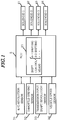
- Fig. 1 is a block diagramof a system configuration of a signal system of the control apparatus.
- this control apparatus is provided with an electronic control unit (ECU) 2 as a core element thereof; various sensors 31-34 as input means for inputting various information thereto, i.e., engine (E/G) revolution sensors 31 for detecting an engine revolution of a vehicle; a throttle opening sensor 32 for detecting an engine load; a shift input shaft revolution sensor 33 for detecting input rotation of the shift; and a vehicle speed sensor 34 for detecting a vehicle speed from output shaft rotation of the shift.
- ECU electronice control unit
- various sensors 31-34 as input means for inputting various information thereto, i.e., engine (E/G) revolution sensors 31 for detecting an engine revolution of a vehicle; a throttle opening sensor 32 for detecting an engine load; a shift input shaft revolution sensor 33 for detecting input rotation of the shift; and a vehicle speed sensor 34 for detecting a vehicle speed from output shaft rotation of the shift.
- E/G engine revolution sensors 31 for detecting an engine revolution of a vehicle
- throttle opening sensor 32 for detecting an engine load
- the control apparatus is further composed of a plurality of solenoids as output means activated by an output of a driving signal based on control information, that is, solenoids 1 to 4 as actuators of solenoid valves 41 to 44 arranged at a hydraulic control unit described later in detail with reference to Fig. 5.
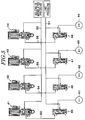
- Fig. 2 is a skeleton diagram of a 6-gear train for a front engine rear wheel drive (FR) vehicle as an example of a shift mechanism control by the above mentioned control apparatus.
- This gear train is composed of a shift mechanism of forward 6-speed stage and 1 reverse stage consisting of a combination of a torque converter 7 with a lockup clutch, a planetary gear set G of Ravigneaux type including a speed reducing gear G1 of simple planetary type.
- the planetary gear set G consisting essentially of the shift mechanism includes two sun gears S2 and S3 each having different diameter; one ring gear R2; a long pinion gear P2 externally geared with a large-diameter sun gear S2 and internally geared with the ring gear R2; a short pinion gear P3 externally geared with a small-diameter sun gear S3 and externally geared with the long pinion gear P2; and a gear set of Ravigneaux type consisting of a carrier C2 for supporting the pinion gears both P2 and P3.
- the small-diameter sun gear S3 of the planetary gear set G is coupled to a multi-plate configured clutch (C-1) (hereinafter, a reference numeral is given immediately following each engagement element); the large-diameter sun gear S2 is coupled with a multi-plate configuration clutch C-3, can be engagingly locked with an automatic transmission case 10 by means of a brake B-1 composed of a band brake, and further, can be engagingly locked with the automatic transmission case 10 by means of a one-way clutch F-1 parallel thereto and a multi-plate configured brake B-2.
- a carrier C2 is coupled with an input shaft 11 via clutch C-2, as an engagement element of the multi-plate configuration.
- This carrier can be engagingly locked with the transmission case 10 by means of the multi-plate configuredbrake B-3, and can be unidirectionally rotated and engagingly locked with the transmission case 10 by means of a one-way clutch F-2.
- a ring gear R2 is coupled with an output shaft 19.
- a deceleration planetary gear G1 is composed of a simple planetary gear, a ring gear R1 as its input element is coupled with the input shaft 11, a carrier C1 as an output element is coupled with the short-diameter sun gear S3 via the clutch C-1, and is coupled with the large-diameter sun gear S2 via the clutch C-3, and a sun gear Sl as a fixing element for obtaining resistance force is fixed to the transmission case 10.
- a relationship between engagement elements that is, between engagement and disengagement ofclutches, brakes, andone-wayclutchesandshift stages is shown in an engagement chart of Fig. 3.
- the mark ⁇ designates engagement
- no-mark designates disengagement
- the mark ⁇ designates engagement for engine brake achievement
- the mark ⁇ designates engagement that does not directly influence achievement of a shift stage.
- Fig. 4 is a speed graph showing a relationship between a shift stage achieved by engagement of each of the clutches, brakes, and one-way clutches ( ⁇ designates engagement thereof) and revolution rate of each shift element at that time.
- a first speed (1st) is achieved by engagement between clutch C-1 and brake B3 (in the illustrative embodiment, as is evident by referring to the activation chart, automatic engagement of one-way clutch F-2 is employed instead of engagement of brake B-3.
- Reasons why this engagement is employed and why this engagement corresponds to engagement of brake B-3 are as follows:
- the one-way clutch F-2 for releasing engagement force itself together with engagement of brake B-1 is employed to avoid complicated hydraulic control for grip change of brakes B-3 and B-1 during 1 ⁇ 2 shifting described later in detail and to simplify disengagement control of brake B-3 which is identical to engagement of brake B-3).
- a second speed (2nd) is achieved by engagement between clutch C-1 and one-way clutch F-1 corresponding to engagement between clutch C-1 and brake B-1 and engagement of brake B-2 that enables these engagements (a reason why these engagements correspond to engagement of brake B-1 will be described later in detail).
- rotation decelerated from input shaft 11 via deceleration planetary gear G1 is inputted to small-diameter sun gear S3 via clutch C-1; the resistance force of large-diameter sun gear S2 engagingly locked by engagement between brake B-2 and one-way clutch F-1 is obtained, and deceleration rotation of ring gear R2 is outputted to the output shaft 19.
- the deceleration rate is lower than the first speed (1st) as shown in Fig. 4.
- a third speed (3rd) is achieved by simultaneous engagement of clutches C-1 and C-3.
- rotation decelerated from an input shaft 11 via deceleration planetary gear G1 is inputted to a large-diameter sun gear S2 and a small-diameter sun gear S3 simultaneously via clutches C-1 and C-3; planetary gear set G is directly connected, and rotation of the ring gear R2 that is the same as input rotation for both of the sun gears is outputted to the output shaft 19 as rotation decelerated with respect to the rotation of input shaft 11.
- a fourth speed (4th) is achieved by simultaneous engagement of clutches C-1 and C-2.
- rotation decelerated from the input shaft 11 via deceleration planetary gear G1 is inputted to the small-diameter sun gear 53 via clutch C-1 whilenon-decelerationrotationinputtedfromtheinputshaft 11 via clutch C-2 is inputted to carrier C2.
- Intermediate rotation of these two inputted rotations are outputted to the output shaft 19 as rotation of ring gear slightly decelerated for rotation of input shaft 11.
- a fifth speed (5th) is achieved by simultaneous engagement of clutches C-2 and C-3.
- rotation decelerated from the input shaft 11 via deceleration planetary gear G1 is inputted to the large-diameter sun gear S2 via clutch C-3 while non-deceleration rotation inputted from the input shaft 11 via clutch C-2 is inputted to carrier C2.
- Rotation slightly accelerated to be higher than that of the input shaft 11 of the ring gear R2 is outputted to the output shaft 19.
- a sixth speed (6th) is achieved by engagement of clutch C-2 and brake B-1.
- non-deceleration rotation is inputted from the input shaftll to carrier C2 only via clutch C-2, resistance force is obtained for sun gear S2 engagingly locked by engagement of brake B-1, and the further accelerated rotation of the ring gear R2 is outputted to the output shaft 19.
- Reverse stage (R) is achieved by engagement between clutch C-3 and brake B-3.
- rotation decelerated from input shaft 11 via deceleration planetary gear G1 is inputted to the large-diameter sun gear S2 via clutch C-3; resistance force is obtained for carrier C2 engagingly locked by engagement of brake B-3, and reverse rotation of the ring gear R2 is outputted to the output shaft 19.
- the engagement direction of the one-way clutch F-1 coupled with the sun gear S2 is set along a resistance force torque support direction at the second speed of the large-diameter sun gear S2, thereby making it possible for one-way clutch to function in the substantially same manner as engagement of brake B-1.
- this sun gear is not only engaged to obtain an engine brake effect during the second gear stage, but also requires brake B-1 because the gear is a shifting element to be engagingly locked for achieving the sixth speed.
- the large-diameter sun gear S2 rotates in reverse direction to input rotation direction at the achievement of the first speed (1st).
- the sun gear rotates in the same direction as input rotation direction. Therefore, one-way clutch F-1 cannot be directly coupled with a fixing member, and thus, is constructed so that the effectiveness of an engagement state can be controlled in alignment with the brake B-2.
- Each of the thus achieved speeds becomes a proper speed step with its relatively constant intervals for each gear step as is qualitatively evident by referring to vertical intervals marked with ⁇ indicative of a speed ratio of the ring gear R2 on the speed graph of Fig. 4.
- This gear train does not require multiple grip change of engagement elements while upshifting/ downshifting between general adjacent speeds, but requires the grip change in a skip shifting.
- the downshift requiring skip shifting corresponds to 6 ⁇ 3 skip shift and 5 ⁇ 2 skip shift (however, in this shifting, the brake B-2 is always engaged for simplification of control in the second or higher speeds, and thus, automatic engagement of one-way clutch F-1 serves as engagement of brake B-1).
- a hydraulic control unit controls the thus constructed shift mechanism by operation of the hydraulic servo of each of clutches and brakes.
- the hydraulic servo of each engagement element is directly controlled individually by means of its own solenoid valve via a solenoid driving signal from electronic control unit 2 so as to achieve the above skip shifting easily.
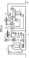
- Fig. 5 shows a specific circuit diagram. As shown in the drawing, in this hydraulic circuit, each of control valves 45 to 48 is connected in parallel to a line pressure oil passage 51 connected to a supply circuit of a line pressure (the maximum circuit pressure capable of engaging the engagement elements with each other according to a vehicle travel load) depicted by a block diagram (any specific construction is not shown). Each control valve is constructed to be activated at a controlled pressure according to the solenoid pressures applied by the respective solenoid valves 41 to 44.
- the hydraulic servo 61 of clutch C-1 is connected to a line pressure oil passage 51 via the C-1 control valve 45, and the spool end of the C-1 control valve 45 is connected to an oil passage 52 of a solenoid modulator pressure via a solenoid valve 41 (oil pressure in which a line pressure is reduced via the modulator valve via the solenoid valve 41).
- the C-1 control valve 45 is a spool valve provided with a land with both ends having different diameters. A solenoid signal pressure is appliedto a large-diameterlanderndagainst a springloadapplied to a small-diameter land.
- a drain port is closed at the large-diameter land; a line pressure oil passage 51 and a hydraulic servo 61 are communicated with each other while a space between an IN port communicating with the line pressure oil passage 51 and an OUT port communicating with a hydraulic servo 61 is throttled by the small-diameter land; the IN port is closed at the small-diameter land by disengagement of the solenoid pressure; and the hydraulic servo 61 is drain-connected by releasing a drain port at the large-diameter land.
- the solenoid valve 41 is an always opened linear solenoid valve.
- a construction is adopted such that throttle between the solenoid modulator pressure oil passage 52 and the solenoid pressure oil passage 53 is adjusted at a load applied to a plunger against a spring load applied to one end of a spool having a land at both ends thereof, and a drain quantity of the solenoid pressure oil passage 53 is adjusted, thus adjusting the solenoid pressure.
- a parallel circuit configuration consisting of similar control valves 46, 47, and 48; solenoid valves 42, 43, and 44; and solenoid pressure oil passages 54, 55, and 56 for communicating these valves with each other.
- the thus constructed automatic transmission requires activation of four engagement elements (clutches C-1, C-2, and C-3; and brake B-1) , for example, during 6 ⁇ 3 shifting in which when a first shifting position is set to a sixth speed, a third speed separated by two gears from the sixth speed is a second shifting position.
- a first shifting position (sixth speed) is achieved by engagement of the first and second engagement elements (brake B-1 and clutch C-2), and a second shifting position is achieved by engagement of the third and fourth engagement elements (clutches C-1 and C-3).
- a first shifting position is a fifth speed
- it when attempting shifting from the fifth speed to the second speed separated by two stages, it also requires activation of four engagement elements (clutches C-1, C-2, and C-3, and one-way clutch F-1) .
- a first engagement element is clutch C-2
- a second engagement element is clutch C-3
- a third engagement element is clutch C-1
- a fourth engagement element is a one-way clutch F-1.
- Such disengagement and engagement of these engagement elements may include a transient slip state leading to complete disengagement/engagement. Therefore, starting disengagement denotes that the engagement elements start slipping. In terms of engagement elements in which this starting is operated by hydraulic pressure, starting disengagement denotes that slipping is started by lowering the engagement force. In terms of a one-way clutch free of hydraulic operation, starting disengagement denotes that the clutch becomes free along with a change in rotational direction of a rotating member. Similarly, completing engagement denotes that the engagement elements no longer slip. Therefore, completing engagement denotes that the engagement elements operated by hydraulic pressure never slip due to the increase in engagement force, and that engagement elements free of hydraulic operation are locked with the rotational direction change of the rotation member.
- the shift control means 21 is further achieved by activation of two engagement elements (clutch C-1 and brake B-1) of the above four engagement elements for a first shifting position (sixth speed or fifth speed) and a second shifting position (third speed or second speed); the means 21 sets a third shifting position (fourth speed or third speed) in which the second shifting position (third speed or second speed) is achieved by activation of the remaining two engagement elements; and the means 21 switches shifting from the first shifting position (sixth speed or fifth speed) to the second shifting position (third speed or second speed) to shift from the third shifting position (fourth speed or third speed) to the second shifting position (third speed or second speed) via shifting from the first shifting position (sixth speed or fifth speed) to the third shifting position (fourth speed or third speed).
- four engagement elements are: clutch C-1 engaged during shifting to the third shifting position ( fourth speed or third speed); brake B-1 or clutch C-2 disengaged during the shifting; clutch C-3 or one-way clutch F-1 engaged during shifting to the second shifting position (third speed or second speed); and clutch C-2 or clutch C-3 disengaged during the shifting.
- the shift control means 21 is constructed as a program in the control apparatus; shifting is performed by controlling the hydraulic servos 61 to 64 for each engagement element through activation of the solenoid valve 41 to 44 using a solenoid driving signal outputted based on the program.
- shifting is performed by controlling the hydraulic servos 61 to 64 for each engagement element through activation of the solenoid valve 41 to 44 using a solenoid driving signal outputted based on the program.
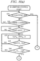
- a control flow of the shift control means 21 will be described for each engagement element.
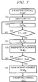
- servo activation control subroutine processing is performed in step S12 .
- This processing is intended to maintain the subsequent piston stroke pressure for reducing a space between a first fill of hydraulic pressure for filling the inside of a hydraulic servo cylinder of clutch C-1 and a hydraulic servo piston and friction member of an engagement element, and is well known as being generally performed for clutch engagement.
- an advancing state (Shift R) is judged as an index for judging advancement of shifting in step S13 (Shift R >S _ End 1).
- This shift advancing state can be the index for judging an input shaft revolution or a hydraulic pressure of the hydraulic servo, and however, in the illustrative embodiment, the input/output shaft revolution is represented as the index expressed by the formula below.
- Shift R (transmission input revolution - gear ratio before shifting x transmission output revolution) x 100 / transmission output revolution x (gear ratio after shifting - gear ratio before shifting) [%]
- the Shift R may be set to, for example, 70% and is calculated based on a detected value by the transmission input shaft revolution sensor 33 and the vehicle sensor 34 shown in Fig. 1.
- a pressure increase for starting engagement of clutch C-1 is started in step S14 (sweep-up at a gradient of dP c1 a).
- this processing denotes that a drive signal current value for solenoid 1 is controlled; the solenoid valve 41 shown in Fig.
- step S15 processing for increasing pressure up to a line pressure is performed to reliably maintain engagement of clutch C-1 in step S16 (sweep-up at a gradient of dP c1 b). During this period, it is repeatedly judged whether or not the servo hydraulic pressure reaches a line pressure in the next step S17 (P c1 > P FULL ) . Thus, when the judgment in step S17 is Yes, 6-4 shifting control for controlling engagement of clutch C-1 ends.
- This processing is intended to prevent revving of the engine due to difference among individual transmission units or dispersion in activation in clutch C-1 caused by aging.
- This constant pressure maintaining time is monitored in the next step S23, and is continued until the judgment becomes Yes (timer t > t _ standby) .
- step S26 when the degree of advancement is judged Yes in step S26 (Shift R > S _ End 2), low-pressure processing is performed for completely removing the servo hydraulic pressure of brake B-1 in the next step S27 (sweep-down at a gradient of dP Ri d).
- This processing itself is completed by solenoid valve 3 reaching a full output, and thus, 6-4 shift control for brake B-1 disengagement ends without performing monitoring judgment in particular.
- step S31 end of 6-4 shifting is judged in step S31.
- step S32 it is judged whether or not a shifting instruction to a third speed is established (3rd judgment). In this manner, the above shifting is discriminated from shifting to another speed.
- judgment of the shift advancing state (Shift R) is started for determining a start timing of lowering the servo hydraulic pressure of clutch C-2 in step S33.
- an indicator for judgment of the shift advancing state is set to the value (Shift R_S) based on a revolution of the shift input shaft.
- a predetermined hydraulic pressure includes a hydraulic pressure (P c2 _ OS) corresponding to the safety factor in the hydraulic pressure (P c2 _ to) corresponding to an input torque to clutch C-2.
- the input torque can be obtained by calculating an engine torque from a map indicating the degree of opening of throttle and the engine revolution; calculating a speed ratio from the input and output rotation frequencies of a torque converter; and multiplying the resultant engine torque by the speed ratio.
- the input torque is converted into a hydraulic pressure by dividing it by a multiple of the piston receiving pressure area, the number of friction members, effective radius, and frictional coefficient of the hydraulic servo for an engagement element, and adding the piston stroke pressure to that value.
- the hydraulic pressure corresponding to the safety factor (P c2 _ OS) is decreased from P c2 a to P c2 b in accordance with the advancement of shift.
- disengagement (slip) of clutch C-2 is started by setting P c2 b to 0. It is the most important aspect of the present invention to set this time point to a point before 100% of shift advancement. This point will be described in detail relative to an engagement (slip) start timing of clutch C-1.
- judgment of shift advancement state (Shift R) is made for judging a stage preceding fourth speed synchronization in the next step S35 (Shift R > S _ End 3).
- step S37 as the initial step for 4-3 shifting control, while the servo pressure (P c2 ) of clutch C-2 is subjected to sweep-down processing at a gradient of dP c2 c, judgment of shift advancement state (Shift R) is performed in step S38 (Shift R > S _ End 2). Then, sweep-down is continued until the judgment becomes Yes.
- step S39 low-pressure processing is performed in step S39 to completely remove the servo hydraulic pressure of clutch C-2 (sweep-down at a gradient of P c2 d). This processing itself is completed by the solenoid valve 2 reaching full output, and 4-3 shifting control ends for C-2 clutch disengagement without performing monitoring judgment in particular. Thus, C-2 disengagement control ends.
- This control is substantially the same as the aforementioned engagement control of clutch C-1 except different start timing.
- servo activation control subroutine processing is performed in step S52.
- This processing is intended for maintaining the subsequent piston stroke pressure for reducing a space between the first fill of the hydraulic pressure for filling the inside of the hydraulic servo cylinder of clutch C-3 and the hydraulic servo piston and the frictional member of an engagement element, and is well known to be generally performed for clutch engagement.
- an advancing state (Shift R) is judged as an index for judging advancement of shift in step S53 (Shift R > S _ End 1).
- step S55 processing for increasing a pressure to a line pressure is performed to reliably maintain engagement of clutch C-3 (sweep-up at a gradient of dP c3 b) in step S56. During this period, it is repeatedly judged whether or not the servo hydraulic pressure reaches the line pressure (P c1 > P FULL ) in the next step S57. Thus, when the judgment in step S57 becomes Yes, 4-3 shifting control ends for controlling engagement of clutch C-3.
- Fig. 11 is a timing chart showing a relationship between the servo hydraulic pressure and the input shaft revolution with respect to activation of four engagement elements by the aforementioned 6 ⁇ 3 shift control.
- the engagement element revolution is positive when the rotation side element rotates in the same direction as engine rotation, and is negative when it rotates in reverse direction.
- a side in which the output element side causes acceleration rotation in engine rotation direction with respect to clutch input rotation is defined to be positive, and the reverse side is defined to be negative.
- engagement control of clutch C-1 and disengagement control of brake B-1 are started simultaneously.
- the servo hydraulic pressure of brake B-1 When the servo hydraulic pressure of brake B-1 is increased to a first fill pressure, the servo hydraulic pressure of brake B-1 is temporarily set to a pressure that is slightly lower than a line pressure at the same time. Then, the pressure is further lowered to a predetermined pressure. In this manner, 6-4 shifting is started, and the input shaft revolution is started toincrease.
- the servo hydraulic pressure of brake B-1 is lowered at a constant gradient; the servo hydraulic pressure of clutch C-1 is maintained to a piston stroke pressure, and clutch C-1 enters an engagement standby state. At this time, as is evident by referring to Fig.
- brake B-1 starts slipping, whereby sun gear S3 is oriented in deceleration direction, and sun gear S2 is oriented in acceleration direction around an engagement point of clutch C-2 being engaged.
- a rotation element side of brake B-1 start rotating in positive direction from a state where engagement equals 0; and an output element side of clutch C-3 is accelerated from negative rotation on the output element with respect to deceleration rotation on the input element side, and rotates in positive direction.
- clutch C-1 is decelerated in a direction identical to the engine rotation at the same speed from a state of positive rotation significantly accelerated with respect to the engine rotation.
- the servo hydraulic pressure of clutch C-1 is switched such that the pressure is increased to the line pressure.
- the servo hydraulic pressure of clutch C-2 during pressure fall control is controlled so as to be a hydraulic pressure suitable to reach the point preceding to the disengagement start by its reduction control when the judgment of a state preceding fourth gear stage synchronization is Yes (S _ End 3) , and thus, a second stage control state in which a gradient is changed from this stage is obtained.
- clutch C-2 slips, and negative rotation occurs.
- clutch C-1 decelerating in a state where a slip is decelerated from a disengagement deceleration state turns to 0 rotation of engagement.
- rotation of clutch C-3 is continuously increased.
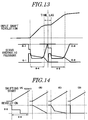
- Fig. 13 is a timing chart showing a conventional two-staged shifting of 6-4 and 4-3 in comparison with the above 6-4-3 shifting.
- a substantial shifting period is the period indicated by the bi-directional arrows 6-4 and 4-3.
- a period indicated as a time lag in the drawing occurs when shifting is not performed substantially continuously.
- a period indicated by the bi-directional arrows 6-4 and 4-3 becomes continuous, making it possible to reduce the shifting period corresponding to the above time lag.
- disengagement of clutch C-2 is started after disengagement start of brake B-1, and engagement of clutch C-1 is completed. Then, engagement of clutch C-3 is completed, thereby maintaining engagement until disengagement start of one engagement element, i.e., clutch C-2 through a shifting period and maintaining engagement from completion of engagement of clutch C-1. In this manner, a shifting period in which engagement is maintained is expanded, and a period in which all of the four engagement elements is slipping is minimized. Moreover, before completing engagement of clutch C-1, disengagement of clutch C-2 is started, thereby obtaining a shift state where two elements are not completely engaged simultaneously during the shift. Thus, continuous shifting free from two-stage shifting can be performed while shifting is advanced in ideal state.
- the hydraulic pressure for clutch C-2 is lowered by a predetermined quantity as a state of shifting to the third shifting position (fourth speed) is advanced.
- engine revving or the like in the middle of shifting to the third shifting position (fourth speed) can be prevented.
- the hydraulic pressure for clutch C-2 is lowered, thus making it possible to start shifting to the second shifting position (third speed) with no time lag.
- clutch C-2 when a standby hydraulic pressure for clutch C-2 is set, clutch C-2 can be theoretically maintained without slipping by setting the standby hydraulic pressure to a hydraulic pressure according to an input torque to be inputted to the transmission. Actually, it is well known to set a margin of a certain safety factor in consideration of dispersion or the like in hardware system. If the safety factor is excessively large, shifting start from the third shifting position (fourth speed) to the second shifting position (third speed) will be delayed. In contrast, if the safety factor is excessively small, in the case where dispersion in hardware system is greater than the safety factor, clutch C-2 slips, and engine revving occurs.
- the above safety factor is sequentially reduced from the maximum value according to the degree of advancement of shifting from the first shifting position (sixth speed) to the third shifting position (fourth speed), thereby making it possible to prevent the delay of the start of shifting to the second shifting position (third speed), and reliably prevent an occurrence of engine revving at the end of shift to the third shifting position (fourth speed).
- control of the servo hydraulic pressure of brake B-1 is lowered to a hydraulic pressure according to an input torque at the same time as shifting start, so that brake B-1 slips, and thus, the input revolution increases immediately. Therefore, this activation is not only helpful to reduce the actual shifting time, but also causes quick shift feeling. In particular, the above activation effectively works in order to improve the response in kick-down shifting and driving comfort, and serves as a skip shifting to respond to the driver's request quickly.
- Fig. 14 (A) - (D) shows a modified example of the characteristics, in which the servo hydraulic pressure of clutch C-2 is swept down from the start of shifting to the fourth speed (rotation change start).
- Fig. 14(A) shows a characteristic example when hydraulic pressure is lower stepwise and maintained;
- Fig. 14 (B) shows an example when hydraulic pressure is lowered at a predetermined gradient; and
- Fig. 14 (C) shows an example when a lowering gradient is changed; and Fig. 14 (D) shows an example when hydraulic pressure is lowered to a predetermined pressure, and maintained there.
- a start timing of lowering the hydraulic pressure may be obtained when issuing a shift instruction.
- the lowering characteristics of hydraulic pressure can adopt various embodiments without limitation to characteristics of the first embodiment.
- FIG. 15 shows a construction of the second embodiment in which the start timing of lowering the hydraulic pressure is changed.
- it is constructed such that lowering of the hydraulic pressure (P c2 ) of clutch C-2 to be disengaged during 4-3 shifting is started when the hydraulic pressure (P c1 ) of clutch C-1 to be engaged at 6-4 shifting exceeds a predetermined value (P c1 s).
- the initial hydraulic pressure (P c2 ) of the low pressure is set to P c2 to + P c2 a.
- the characteristics indicated by the dashed line of the drawing shows the hydraulic pressure characteristics when a safety factor is not considered.
- the start timing of lowering the hydraulic pressure can be controlled by judgment based on an increase in servo hydraulic pressure of clutch C-1 to be specifically engaged.
- Fig. 16 shows a construction of the third embodiment in which lowering of the hydraulic pressure (P c2 ) of clutch C-2 to be disengaged at 4-3 shifting is timer-controlled.
- shift advancement is estimated by counting using a timer (t) started at the start of 6-4 shifting, and lowering of the hydraulic pressure is started in comparison with a predetermined time (Time 1) set in advance in accordance with a timing before synchronization of the fourth speed.
- This predetermined time (Time 1) may be stored in a memory of the shift apparatus in the form of a map.
- the characteristics indicated by the dashed line of the drawing show the hydraulic pressure characteristics when the safety factor is not considered.
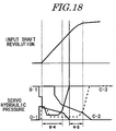
- Fig. 17 shows a construction of the fourth embodiment in which lowering of the hydraulic pressure (P c2 ) to be disengaged at 4-3 shifting is controlled based on the input/output shaft revolution of the transmission.
- a time (T) elapsing until clutch C-2 starts slipping is set in advance through experiment or the like. Then a change of input shaft rotation within the time (T) is obtained by detecting an acceleration of the input rotation ( ⁇ Nt) during 6-4 shifting, thereby obtaining the number of changes that occurred in the revolution.
- the output shaft revolution of the transmission when 6-4 shifting is started is multiplied by a gear ratio after shifting (fourth speed), whereby the input shaft revolution of the shifting is predicted at the end of 6-4 shifting.
- the characteristics indicated by the dashed line in the figure shows the hydraulic pressure characteristics when the safety factor is not considered.
- Fig. 18 is a timing chart showing the fifth embodiment in which the above control is changed.
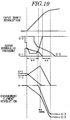
- Fig. 19 is a timing chart showing 5 ⁇ 2 (5-3-2) shifting.
- clutch C-2 is disengaged and controlled in a similar control method in place of brake B-1 in the first embodiment
- clutch C-3 is disengaged and controlled in the similar method in place of clutch C-2.
- engagement of brake B-1 to be substituted for clutch C-3 is switched to automatic engagement of the one-way clutch F-1, thus making it non-controllable.
- the rotation of each engagement element is substituted by a description through inquiry between a graph of the engagement element revolution depicted by a method similar to the timing chart shown in Fig. 11 of the first embodiment and a speed graph of Fig. 4.
- shifting in shifting from the third shifting position (third speed) to the second shifting position (second speed), shifting can be performed merely by manipulating clutch C-3 as a second engagement element on the disengagement side, thus making it possible to achieve simplified control.
- the one-way clutch F-1 is automatically locked at the same time as complete disengagement of clutch C-2, thus ending shifting, and making it possible to shorten the shifting period.
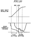
- Fig. 20 Although it does not apply to the exemplified gear train, there is shown a timing chart showing shifting in the case of gear train in which the one-way clutch engagement is employed in place of brake engagement at the third shifting position in reverse to the above engagement relationship.
- synchronization with the third shifting position in the first shifting position can be judged by locking of the one-way clutch constituting the third engagement element.
- hydraulic pressure control for engagement is directed to control of the servo pressure that is only an engagement element during the second shift stage, thus making control simpler.
- This shifting control apparatus includes shift control means for starting disengagement of a second engagement element C-2 after starting disengagement of a first engagement element B-1; completing engagement of a fourth engagement element C-3 after completing engagement of a third engagement element C-1; and starting disengagement of a second engagement element C-2 before completing engagement of a third engagement element C-1.
- This shifting control apparatus includes shift control means for starting disengagement of a second engagement element C-2 after starting disengagement of a first engagement element B-1; completing engagement of a fourth engagement element C-3 after completing engagement of a third engagement element C-1; and starting disengagement of a second engagement element C-2 before completing engagement of a third engagement element C-1.
Landscapes
- Engineering & Computer Science (AREA)
- General Engineering & Computer Science (AREA)
- Mechanical Engineering (AREA)
- Control Of Transmission Device (AREA)
- Structure Of Transmissions (AREA)
Applications Claiming Priority (2)
| Application Number | Priority Date | Filing Date | Title |
|---|---|---|---|
| JP31172199 | 1999-11-01 | ||
| JP31172199A JP4665274B2 (ja) | 1999-11-01 | 1999-11-01 | 自動変速機の変速制御装置 |
Publications (3)
| Publication Number | Publication Date |
|---|---|
| EP1096178A2 true EP1096178A2 (fr) | 2001-05-02 |
| EP1096178A3 EP1096178A3 (fr) | 2003-11-19 |
| EP1096178B1 EP1096178B1 (fr) | 2006-06-14 |
Family
ID=18020683
Family Applications (1)
| Application Number | Title | Priority Date | Filing Date |
|---|---|---|---|
| EP99126175A Expired - Lifetime EP1096178B1 (fr) | 1999-11-01 | 1999-12-29 | Dispositif et méthode de commande de changement de vitesse pour transmission automatique |
Country Status (5)
| Country | Link |
|---|---|
| US (1) | US6270444B1 (fr) |
| EP (1) | EP1096178B1 (fr) |
| JP (1) | JP4665274B2 (fr) |
| KR (1) | KR100643076B1 (fr) |
| DE (1) | DE69931922T2 (fr) |
Cited By (8)
| Publication number | Priority date | Publication date | Assignee | Title |
|---|---|---|---|---|
| EP1308649A3 (fr) * | 2001-10-31 | 2004-12-08 | Aisin Aw Co., Ltd. | Dispositif de commande d'embrayage de pontage pour transmission automatique |
| EP1219868A3 (fr) * | 2000-12-28 | 2007-09-05 | Aisin Aw Co., Ltd. | Dispositif de commande de changement de vitesses pour transmission automatique |
| EP1431625A4 (fr) * | 2001-09-28 | 2007-10-03 | Jatco Ltd | Dispositif de commande de changement de vitesse pour boite de vitesses automatique |
| EP1336773A3 (fr) * | 2002-02-18 | 2008-04-23 | Aisin Aw Co., Ltd. | Dispositif de commande de véhicule |
| WO2008126813A3 (fr) * | 2007-04-06 | 2009-06-11 | Toyota Motor Co Ltd | Véhicule, procédé de commande et appareil de commande pour une transmission automatique |
| EP2133597A3 (fr) * | 2008-06-11 | 2010-10-06 | JATCO Ltd | Appareil de contrôle hydraulique pour une transmission automatique |
| DE10321961B4 (de) * | 2002-05-17 | 2014-04-30 | Aisin Aw Co., Ltd. | Schaltsteuergerät für ein Automatikgetriebe |
| DE10321474B4 (de) * | 2002-05-20 | 2016-03-03 | Aisin Aw Co., Ltd. | Schaltsteuereinrichtung für Automatikgetriebe |
Families Citing this family (37)
| Publication number | Priority date | Publication date | Assignee | Title |
|---|---|---|---|---|
| WO2000029765A1 (fr) * | 1998-11-16 | 2000-05-25 | Yanmar Diesel Engine Co., Ltd. | Procede de regulation de la pression hydraulique dans un mecanisme de changement de vitesse avec un embrayage hydraulique |
| JP4524917B2 (ja) * | 2000-12-28 | 2010-08-18 | アイシン・エィ・ダブリュ株式会社 | 自動変速機の変速制御装置 |
| JP4770021B2 (ja) | 2000-12-28 | 2011-09-07 | アイシン・エィ・ダブリュ株式会社 | 自動変速機の変速制御装置 |
| JP4929528B2 (ja) * | 2001-03-22 | 2012-05-09 | アイシン精機株式会社 | 自動変速機の油圧制御装置 |
| JP2002295663A (ja) * | 2001-03-30 | 2002-10-09 | Aisin Aw Co Ltd | 自動変速機の変速制御装置 |
| KR100412739B1 (ko) * | 2001-12-27 | 2003-12-31 | 현대자동차주식회사 | 차량용 자동 변속기의 6속 변속 제어방법 |
| JP2004052807A (ja) * | 2002-07-16 | 2004-02-19 | Jatco Ltd | 自動変速機用歯車変速装置 |
| KR100489094B1 (ko) * | 2002-12-05 | 2005-05-12 | 현대자동차주식회사 | 6속 자동 변속기의 변속 경로 제어 방법 |
| JP4210681B2 (ja) * | 2005-10-03 | 2009-01-21 | ジヤトコ株式会社 | 自動変速機の制御装置 |
| JP4604951B2 (ja) * | 2005-10-07 | 2011-01-05 | トヨタ自動車株式会社 | 自動変速機の制御装置 |
| KR100680641B1 (ko) * | 2005-12-12 | 2007-02-08 | 현대자동차주식회사 | 6속 자동변속기의 유압제어시스템 |
| JP4257328B2 (ja) * | 2005-12-26 | 2009-04-22 | ジヤトコ株式会社 | 自動変速機の制御装置 |
| DE102006026601A1 (de) * | 2006-06-08 | 2007-12-13 | Zf Friedrichshafen Ag | Verfahren zum Betreiben eines Antriebsstrangs |
| DE102006026597A1 (de) * | 2006-06-08 | 2007-03-29 | Zf Friedrichshafen Ag | Verfahren zum Betreiben eines Antriebsstrangs |
| US7713170B2 (en) * | 2006-07-31 | 2010-05-11 | Hyundai Motor Company | Shift control method of automatic transmission |
| JP4760631B2 (ja) | 2006-09-08 | 2011-08-31 | トヨタ自動車株式会社 | 自動変速機の制御装置、制御方法およびその方法をコンピュータに実現させるプログラムならびにそのプログラムを記録した記録媒体 |
| JP4162024B2 (ja) | 2006-09-13 | 2008-10-08 | トヨタ自動車株式会社 | 車両用自動変速機の制御装置 |
| JP4894424B2 (ja) * | 2006-09-14 | 2012-03-14 | トヨタ自動車株式会社 | 自動変速機の制御装置 |
| US7894965B2 (en) * | 2006-11-29 | 2011-02-22 | Chrysler Group Llc | Swap shift control scheme for an automatic transmission |
| KR100887960B1 (ko) * | 2007-08-07 | 2009-03-12 | 현대자동차주식회사 | 자동변속기의 변속 제어 방법 |
| JP2009097619A (ja) * | 2007-10-16 | 2009-05-07 | Toyota Motor Corp | 自動変速機の制御装置および制御方法 |
| KR100969366B1 (ko) * | 2007-11-15 | 2010-07-09 | 현대자동차주식회사 | 자동변속기의 변속 제어 방법 |
| JP5031591B2 (ja) * | 2008-01-08 | 2012-09-19 | 本田技研工業株式会社 | 変速機 |
| US8113989B2 (en) * | 2008-10-02 | 2012-02-14 | Ford Global Technologies, Llc | Control of sequential downshifts in a transmission |
| JP4750840B2 (ja) * | 2008-12-08 | 2011-08-17 | ジヤトコ株式会社 | 自動変速機の制御装置 |
| JP4750839B2 (ja) * | 2008-12-08 | 2011-08-17 | ジヤトコ株式会社 | 自動変速機の制御装置 |
| JP5012969B2 (ja) * | 2010-07-20 | 2012-08-29 | トヨタ自動車株式会社 | 自動変速機の制御装置 |
| JP4978727B2 (ja) * | 2010-11-15 | 2012-07-18 | トヨタ自動車株式会社 | 自動変速機の制御装置、制御方法およびその方法をコンピュータに実現させるプログラムならびにそのプログラムを記録した記録媒体 |
| JP5905580B2 (ja) * | 2012-08-09 | 2016-04-20 | ジヤトコ株式会社 | 自動変速機の制御装置及び制御方法 |
| KR101896311B1 (ko) * | 2012-09-20 | 2018-09-07 | 현대자동차 주식회사 | 변속기의 제어방법 및 이를 수행하는 변속시스템 |
| US9217502B2 (en) * | 2013-01-17 | 2015-12-22 | Stanley Wierzbowski | Electronic transmission control system |
| WO2014141368A1 (fr) * | 2013-03-11 | 2014-09-18 | トヨタ自動車株式会社 | Dispositif de commande pour transmission automatique |
| JP6432565B2 (ja) * | 2016-07-20 | 2018-12-05 | トヨタ自動車株式会社 | 自動変速機の制御装置 |
| JP6380478B2 (ja) * | 2016-07-21 | 2018-08-29 | トヨタ自動車株式会社 | 自動変速機の制御装置 |
| KR101924367B1 (ko) | 2017-06-07 | 2018-12-03 | 현대 파워텍 주식회사 | 자동 변속기의 킥다운 변속 제어 장치 및 방법 |
| JP7131417B2 (ja) * | 2019-02-01 | 2022-09-06 | トヨタ自動車株式会社 | 車両の制御装置 |
| JP7239348B2 (ja) * | 2019-02-28 | 2023-03-14 | トヨタ自動車株式会社 | 自動変速機の制御装置 |
Citations (1)
| Publication number | Priority date | Publication date | Assignee | Title |
|---|---|---|---|---|
| EP0434525B1 (fr) | 1989-12-18 | 1994-07-06 | Pierre André Georges Lepelletier | Transmission automatique multivitesses pour véhicule automobile |
Family Cites Families (11)
| Publication number | Priority date | Publication date | Assignee | Title |
|---|---|---|---|---|
| JPS61127959A (ja) * | 1984-11-22 | 1986-06-16 | Toyota Motor Corp | 車両用自動変速機の変速制御方法 |
| US4727774A (en) * | 1985-07-31 | 1988-03-01 | Aisin-Warner Kabushiki Kaisha | Cut-back pressure control device for multi-speed automatic transmission |
| JP2879861B2 (ja) * | 1991-06-14 | 1999-04-05 | 本田技研工業株式会社 | 自動変速機の変速制御方法 |
| JP2850615B2 (ja) * | 1992-01-07 | 1999-01-27 | 日産自動車株式会社 | 自動変速機の変速制御装置 |
| JPH05315898A (ja) * | 1992-05-13 | 1993-11-26 | Yokogawa Electric Corp | トリガ同期回路 |
| JPH06185604A (ja) * | 1992-12-15 | 1994-07-08 | Mazda Motor Corp | 自動変速機の変速制御装置 |
| JP3094747B2 (ja) * | 1993-09-29 | 2000-10-03 | アイシン・エィ・ダブリュ株式会社 | 自動変速機の制御装置 |
| JP3429588B2 (ja) * | 1995-01-10 | 2003-07-22 | 三菱電機株式会社 | 自動変速機の変速制御装置 |
| JP3470508B2 (ja) * | 1996-05-29 | 2003-11-25 | トヨタ自動車株式会社 | 自動変速機の変速制御装置 |
| JP3861328B2 (ja) * | 1996-06-19 | 2006-12-20 | アイシン・エィ・ダブリュ株式会社 | 自動変速機の制御装置 |
| US5682792A (en) * | 1996-06-28 | 1997-11-04 | Caterpillar Inc. | Dependent latching system for a transmission |
-
1999
- 1999-11-01 JP JP31172199A patent/JP4665274B2/ja not_active Expired - Lifetime
- 1999-12-17 KR KR1019990058631A patent/KR100643076B1/ko not_active Expired - Fee Related
- 1999-12-20 US US09/466,872 patent/US6270444B1/en not_active Expired - Lifetime
- 1999-12-29 EP EP99126175A patent/EP1096178B1/fr not_active Expired - Lifetime
- 1999-12-29 DE DE69931922T patent/DE69931922T2/de not_active Expired - Lifetime
Patent Citations (1)
| Publication number | Priority date | Publication date | Assignee | Title |
|---|---|---|---|---|
| EP0434525B1 (fr) | 1989-12-18 | 1994-07-06 | Pierre André Georges Lepelletier | Transmission automatique multivitesses pour véhicule automobile |
Cited By (9)
| Publication number | Priority date | Publication date | Assignee | Title |
|---|---|---|---|---|
| EP1219868A3 (fr) * | 2000-12-28 | 2007-09-05 | Aisin Aw Co., Ltd. | Dispositif de commande de changement de vitesses pour transmission automatique |
| EP1431625A4 (fr) * | 2001-09-28 | 2007-10-03 | Jatco Ltd | Dispositif de commande de changement de vitesse pour boite de vitesses automatique |
| EP1308649A3 (fr) * | 2001-10-31 | 2004-12-08 | Aisin Aw Co., Ltd. | Dispositif de commande d'embrayage de pontage pour transmission automatique |
| EP1336773A3 (fr) * | 2002-02-18 | 2008-04-23 | Aisin Aw Co., Ltd. | Dispositif de commande de véhicule |
| DE10321961B4 (de) * | 2002-05-17 | 2014-04-30 | Aisin Aw Co., Ltd. | Schaltsteuergerät für ein Automatikgetriebe |
| DE10321474B4 (de) * | 2002-05-20 | 2016-03-03 | Aisin Aw Co., Ltd. | Schaltsteuereinrichtung für Automatikgetriebe |
| WO2008126813A3 (fr) * | 2007-04-06 | 2009-06-11 | Toyota Motor Co Ltd | Véhicule, procédé de commande et appareil de commande pour une transmission automatique |
| EP2133597A3 (fr) * | 2008-06-11 | 2010-10-06 | JATCO Ltd | Appareil de contrôle hydraulique pour une transmission automatique |
| US8202186B2 (en) | 2008-06-11 | 2012-06-19 | Jatco Ltd | Hydraulic control apparatus for automatic transmission |
Also Published As
| Publication number | Publication date |
|---|---|
| KR20010049142A (ko) | 2001-06-15 |
| US6270444B1 (en) | 2001-08-07 |
| EP1096178B1 (fr) | 2006-06-14 |
| JP4665274B2 (ja) | 2011-04-06 |
| DE69931922D1 (de) | 2006-07-27 |
| DE69931922T2 (de) | 2007-01-11 |
| KR100643076B1 (ko) | 2006-11-13 |
| JP2001132835A (ja) | 2001-05-18 |
| EP1096178A3 (fr) | 2003-11-19 |
Similar Documents
| Publication | Publication Date | Title |
|---|---|---|
| EP1096178B1 (fr) | Dispositif et méthode de commande de changement de vitesse pour transmission automatique | |
| US6832976B2 (en) | Shift control apparatus for automatic transmission | |
| EP1219869B1 (fr) | Dispositif de commande de changement de vitesses pour transmission automatique | |
| JP4691816B2 (ja) | 自動変速機の制御装置 | |
| EP1906061B1 (fr) | Métode de commande de rétrogradage pour une transmission | |
| US6503165B1 (en) | Hydraulic control device for automatic transmission | |
| EP2136109A2 (fr) | Système de contrôle de changement de vitesse d'une transmission automatique | |
| US6955629B2 (en) | Shift control apparatus for an automatic transmission | |
| EP1249644B1 (fr) | Dispositif de commande de changement de vitesse pour des transmissions automatiques | |
| JP4201111B2 (ja) | 自動変速機のロックアップ制御装置 | |
| JP3130615B2 (ja) | 自動変速機のサーボ油圧制御装置 | |
| JP3872640B2 (ja) | 自動変速機の変速制御装置 | |
| JPH023768A (ja) | 自動変速機の変速制御装置 | |
| JP5007984B2 (ja) | 自動変速機の変速制御装置 | |
| JP3938840B2 (ja) | 自動変速機の再変速禁止制御装置 | |
| US20020028728A1 (en) | Apparatus and method for controlling automatic transmission | |
| JPH10318364A (ja) | 自動変速機のセレクト制御装置 | |
| JP4353776B2 (ja) | 自動変速機の制御方法 | |
| JPH06341526A (ja) | 自動変速機の変速制御装置 | |
| JP2008106829A (ja) | 車両用自動変速機の変速制御装置 | |
| JPH1137271A (ja) | 自動変速機の変速油圧制御装置 |
Legal Events
| Date | Code | Title | Description |
|---|---|---|---|
| PUAI | Public reference made under article 153(3) epc to a published international application that has entered the european phase |
Free format text: ORIGINAL CODE: 0009012 |
|
| AK | Designated contracting states |
Kind code of ref document: A2 Designated state(s): AT BE CH CY DE DK ES FI FR GB GR IE IT LI LU MC NL PT SE |
|
| AX | Request for extension of the european patent |
Free format text: AL;LT;LV;MK;RO;SI |
|
| PUAL | Search report despatched |
Free format text: ORIGINAL CODE: 0009013 |
|
| AK | Designated contracting states |
Kind code of ref document: A3 Designated state(s): AT BE CH CY DE DK ES FI FR GB GR IE IT LI LU MC NL PT SE |
|
| AX | Request for extension of the european patent |
Extension state: AL LT LV MK RO SI |
|
| 17P | Request for examination filed |
Effective date: 20040514 |
|
| AKX | Designation fees paid |
Designated state(s): DE FR GB |
|
| 17Q | First examination report despatched |
Effective date: 20041102 |
|
| GRAP | Despatch of communication of intention to grant a patent |
Free format text: ORIGINAL CODE: EPIDOSNIGR1 |
|
| GRAS | Grant fee paid |
Free format text: ORIGINAL CODE: EPIDOSNIGR3 |
|
| GRAA | (expected) grant |
Free format text: ORIGINAL CODE: 0009210 |
|
| AK | Designated contracting states |
Kind code of ref document: B1 Designated state(s): DE FR GB |
|
| REG | Reference to a national code |
Ref country code: GB Ref legal event code: FG4D |
|
| REF | Corresponds to: |
Ref document number: 69931922 Country of ref document: DE Date of ref document: 20060727 Kind code of ref document: P |
|
| ET | Fr: translation filed | ||
| PLBE | No opposition filed within time limit |
Free format text: ORIGINAL CODE: 0009261 |
|
| STAA | Information on the status of an ep patent application or granted ep patent |
Free format text: STATUS: NO OPPOSITION FILED WITHIN TIME LIMIT |
|
| 26N | No opposition filed |
Effective date: 20070315 |
|
| REG | Reference to a national code |
Ref country code: FR Ref legal event code: PLFP Year of fee payment: 17 |
|
| REG | Reference to a national code |
Ref country code: FR Ref legal event code: PLFP Year of fee payment: 18 |
|
| REG | Reference to a national code |
Ref country code: FR Ref legal event code: PLFP Year of fee payment: 19 |
|
| PGFP | Annual fee paid to national office [announced via postgrant information from national office to epo] |
Ref country code: DE Payment date: 20181218 Year of fee payment: 20 |
|
| PGFP | Annual fee paid to national office [announced via postgrant information from national office to epo] |
Ref country code: FR Payment date: 20181120 Year of fee payment: 20 Ref country code: GB Payment date: 20181227 Year of fee payment: 20 |
|
| REG | Reference to a national code |
Ref country code: DE Ref legal event code: R071 Ref document number: 69931922 Country of ref document: DE |
|
| REG | Reference to a national code |
Ref country code: GB Ref legal event code: PE20 Expiry date: 20191228 |
|
| PG25 | Lapsed in a contracting state [announced via postgrant information from national office to epo] |
Ref country code: GB Free format text: LAPSE BECAUSE OF EXPIRATION OF PROTECTION Effective date: 20191228 |