EP1096181A2 - Joint de culasse à couches multiples comportant une couche externe - Google Patents
Joint de culasse à couches multiples comportant une couche externe Download PDFInfo
- Publication number
- EP1096181A2 EP1096181A2 EP00115944A EP00115944A EP1096181A2 EP 1096181 A2 EP1096181 A2 EP 1096181A2 EP 00115944 A EP00115944 A EP 00115944A EP 00115944 A EP00115944 A EP 00115944A EP 1096181 A2 EP1096181 A2 EP 1096181A2
- Authority
- EP
- European Patent Office
- Prior art keywords
- cylinder head
- head gasket
- combustion chamber
- chamber surround
- cylinder
- Prior art date
- Legal status (The legal status is an assumption and is not a legal conclusion. Google has not performed a legal analysis and makes no representation as to the accuracy of the status listed.)
- Granted
Links
- 238000002485 combustion reaction Methods 0.000 claims abstract description 70
- 239000010410 layer Substances 0.000 claims abstract description 38
- 239000002346 layers by function Substances 0.000 claims abstract description 10
- 239000011324 bead Substances 0.000 claims description 17
- 239000000463 material Substances 0.000 claims description 13
- 238000007789 sealing Methods 0.000 claims description 13
- 239000008186 active pharmaceutical agent Substances 0.000 claims description 6
- 239000011248 coating agent Substances 0.000 claims description 4
- 238000000576 coating method Methods 0.000 claims description 4
- 125000006850 spacer group Chemical group 0.000 claims description 4
- 229910000639 Spring steel Inorganic materials 0.000 claims description 2
- 229910000831 Steel Inorganic materials 0.000 claims description 2
- 230000006698 induction Effects 0.000 claims description 2
- 229910001220 stainless steel Inorganic materials 0.000 claims description 2
- 239000010935 stainless steel Substances 0.000 claims description 2
- 239000010959 steel Substances 0.000 claims description 2
- 239000011521 glass Substances 0.000 description 4
- 230000003068 static effect Effects 0.000 description 3
- 238000010276 construction Methods 0.000 description 2
- 238000011161 development Methods 0.000 description 2
- 230000018109 developmental process Effects 0.000 description 2
- 238000005553 drilling Methods 0.000 description 2
- 230000003993 interaction Effects 0.000 description 2
- XLYOFNOQVPJJNP-UHFFFAOYSA-N water Substances O XLYOFNOQVPJJNP-UHFFFAOYSA-N 0.000 description 2
- 230000009286 beneficial effect Effects 0.000 description 1
- 230000015572 biosynthetic process Effects 0.000 description 1
- 230000001419 dependent effect Effects 0.000 description 1
- 230000000694 effects Effects 0.000 description 1
- 238000000034 method Methods 0.000 description 1
- 230000007704 transition Effects 0.000 description 1
Images

Classifications
-
- F—MECHANICAL ENGINEERING; LIGHTING; HEATING; WEAPONS; BLASTING
- F16—ENGINEERING ELEMENTS AND UNITS; GENERAL MEASURES FOR PRODUCING AND MAINTAINING EFFECTIVE FUNCTIONING OF MACHINES OR INSTALLATIONS; THERMAL INSULATION IN GENERAL
- F16J—PISTONS; CYLINDERS; SEALINGS
- F16J15/00—Sealings
- F16J15/02—Sealings between relatively-stationary surfaces
- F16J15/06—Sealings between relatively-stationary surfaces with solid packing compressed between sealing surfaces
- F16J15/08—Sealings between relatively-stationary surfaces with solid packing compressed between sealing surfaces with exclusively metal packing
- F16J15/0818—Flat gaskets
- F16J15/0825—Flat gaskets laminated
-
- F—MECHANICAL ENGINEERING; LIGHTING; HEATING; WEAPONS; BLASTING
- F16—ENGINEERING ELEMENTS AND UNITS; GENERAL MEASURES FOR PRODUCING AND MAINTAINING EFFECTIVE FUNCTIONING OF MACHINES OR INSTALLATIONS; THERMAL INSULATION IN GENERAL
- F16J—PISTONS; CYLINDERS; SEALINGS
- F16J15/00—Sealings
- F16J15/02—Sealings between relatively-stationary surfaces
- F16J15/06—Sealings between relatively-stationary surfaces with solid packing compressed between sealing surfaces
- F16J15/08—Sealings between relatively-stationary surfaces with solid packing compressed between sealing surfaces with exclusively metal packing
- F16J15/0818—Flat gaskets
- F16J2015/0837—Flat gaskets with an edge portion folded over a second plate or shim
-
- F—MECHANICAL ENGINEERING; LIGHTING; HEATING; WEAPONS; BLASTING
- F16—ENGINEERING ELEMENTS AND UNITS; GENERAL MEASURES FOR PRODUCING AND MAINTAINING EFFECTIVE FUNCTIONING OF MACHINES OR INSTALLATIONS; THERMAL INSULATION IN GENERAL
- F16J—PISTONS; CYLINDERS; SEALINGS
- F16J15/00—Sealings
- F16J15/02—Sealings between relatively-stationary surfaces
- F16J15/06—Sealings between relatively-stationary surfaces with solid packing compressed between sealing surfaces
- F16J15/08—Sealings between relatively-stationary surfaces with solid packing compressed between sealing surfaces with exclusively metal packing
- F16J15/0818—Flat gaskets
- F16J2015/0856—Flat gaskets with a non-metallic coating or strip
Definitions
- the present invention relates to a multi-layer cylinder head gasket with openings corresponding to a number of combustion chambers of an internal combustion engine with inserted Cylinder liners and with a combustion chamber surround arranged towards an opening wherein the combustion chamber surround at least one functional position of the cylinder head gasket surrounds, a full bead (5) of the functional position within the combustion chamber surround (2) (3) is arranged.
- Cylinder head gaskets are used for gas as well as water and oil sealing Transitions of lines and cylinder bore from a first to a second material.
- the combustion chamber gas seal is subject to high levels Conditions. To be able to guarantee a statically sufficient tightness, are certain surface pressures necessary, which require a force distribution such that the majority of the available screw forces are targeted in the area of Combustion chamber sealing is initiated.
- static load add an additional, superimposed dynamic load, whereby at the combustion force generated in the combustion chamber every work cycle of the internal combustion engine relieves the pressure on the combustion chamber seal.
- cylinder head gaskets of various types are known. For example, going from JP 62-206258 out a cylinder head gasket having a seal envelope as a fire ring in the form of a Umkröpfung. A full bead is arranged in this crimp, the bulge of which either points towards the valves or away from them. From US 5,280,929 a cylinder head gasket is known which provides a seal for several cylinders. A sealing of the cylinder head gasket provides a flange, in which two or more layers are arranged, a bead being arranged inside the flange.
- the cylinder head gasket is dimensioned with respect to the internal passages in such a way that the flanging extends into the respective passage between the cylinder head and the cylinder block.
- a cylinder head gasket is known from US Pat. No. 4,898,396, which has a flange with a full bead arranged in the flange. The flanging serves as sealing of the combustion chamber and defines the cylinder bore.
- a cylinder head gasket is known from US Pat. No. 5,161,809 in which material thicknesses of an end plate and a plate connected to it are to be coordinated with one another in such a way that a surface tension suitable for sealing is generated.
- the object of the present invention is to provide a cylinder head gasket which a good sealing effect with static as well as dynamic forces guaranteed and on the other with the construction of diesel engines in particular used cylinder liners is tunable.
- a multi-layer cylinder head gasket according to the invention has openings corresponding to one Number of combustion chambers of an internal combustion engine and one towards an opening arranged combustion chamber surround, the combustion chamber surround at least one Functional position of the cylinder head gasket includes, within the combustion chamber surround a full bead of the functional layer is arranged.
- the cylinder head gasket has one Outer layer, which is arranged separately from the combustion chamber surround, the External position with the cylinder head gasket detached from the combustion chamber surround at least one other layer of the cylinder head gasket is connected. This decoupling
- the outer location of the combustion chamber surround enables a particularly high degree of flexibility Cylinder head gasket while providing a high pressing force.
- Both a corrugated functional layer and a distance layer can be used as the outer layer used.
- the distance layer is designed without additional beads and is therefore flat.
- a first edge of the outer layer is directly a second edge of the Facing the combustion chamber, with both edges separating a gap that is preferably at least 0.3 millimeters.
- Flanging is expediently used as the combustion chamber surround, in which following additional configurations of the cylinder head gasket such a flanging exemplary.
- the flanging has a height that is between 0 mm and 0.3 mm is larger compared to a remaining height of the cylinder head gasket, preferably this difference in height is between 0.1 and 0.2 mm, in particular approximately 0.15 mm.
- this difference in height is between 0.1 and 0.2 mm, in particular approximately 0.15 mm.
- the cylinder head gasket which is adapted to the forces acting on the diesel engine, is constructed so that the flanging is made of a pullable stainless steel sheet, the full bead in a spring steel sheet is arranged and the cylinder head gasket a spacer in Form of a steel sheet for adjusting the thickness of the cylinder head gasket, which can be found in the Flanging extends into it.
- a first material thickness DM of the flanging has a relationship to one second material thickness DS of the outer layer of DM: DS of approximately 1: 1.2 to 1: 1.5.
- the first material thickness DM has a size of approximately 0.2 mm
- the second Material thickness DS a size of about 0.25 mm.
- this type of Construction of the cylinder head gasket that the flanging in relation to the outer layer provides great flexibility.
- This degree of freedom is at least 0.3 mm. This allows relative movements to be exerted along the cylinder head gasket are compensated for by the elastic behavior of the cylinder head gasket.
- a special stiffness of the combustion chamber seal can be achieved by the Flanging is at least partially hardened, especially by means of induction hardening.
- an area of the flanging can be made more rigid than one other area, so that the flare itself the rigidity of the gas-sealing Areas of the cylinder head gasket decisively determined.
- at least one outer surface of the flanging has a friction-reducing and / or sealing coating. This ensures that a long lifespan with a cylinder head gasket can be achieved because the wear on the gasket itself is caught in particular by the coating.
- a geometry of the flanging preferably has an approximately perpendicular one Web, whose extension is approximately parallel to an extension of the cylinder liner runs.
- the flanging is particularly rigid from a certain area educated. This can prevent deformation of this area, so that the forces occurring over the other areas of the flanging as well as in the Flanging arranged layers are included.
- Another embodiment of the Flanging provides that the geometry of the flanging is V-shaped. The legs of the V are flexible, either partially or as a whole.
- Another embodiment of the geometry of the flanging is curved so that a Extension of a first and a second end of the flanging along one Extending the flanging would lead to an overlap. This leads to one that the flexibility of the flanging is made available. On the other hand this geometry also serves to secure the components of the cylinder head gasket. In the event of of a break, the flanging remains on the rest of the part due to the shape of the bead Cylinder head gasket attached and cannot get into the combustion chamber.
- the constructive design of the cylinder head gasket described above allows a high degree of adaptability to differently designed internal combustion engines.
- a cylinder head gasket allows one separate arrangement of a one-piece combustion chamber enclosure to an opening in the Cylinder head gasket for a combustion chamber.
- the arrangement ensures a one-piece Combustion chamber surround around a cylinder that the statically set attraction forces this cylinder only largely affected this individual combustion chamber surround. The pulling forces acting on the other cylinders can thus affect the respective ones there The combustion chamber surround can be adjusted.
- One between the combustion chamber surrounds In contrast, any interference that occurs occurs.
- Another Design provides that at least two openings of the cylinder head gaskets each have assigned a combustion chamber surround, which are integrally connected to one another, quasi in the form of "glasses".
- the combustion chamber surround in the form of the flanging is particularly so dimensioned that their longitudinal dimension less than / equal to a wall thickness of Cylinder liner is.
- the flanging its arrangement in relation to the cylinder bore and the flexibility provided by the full bead as well as by a Extension of their material layer from the cylinder liner in the area between Cylinder head and engine block are particularly good options for dynamic Forces during operation of a diesel engine, for example.
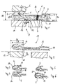
- Figure 1 shows a first cylinder head gasket 1 in cross section.
- the first Cylinder head gasket 1 has a seal, not shown Combustion chamber as a combustion chamber surround a flange 2.
- the flange 2 is out of one piece. It includes a first functional layer 3 and a first spacing layer 4.
- the first functional layer 3 has a full bead 5.
- the full bead 5 is between the flanging 2 arranged.
- the full bead 5 interacts with the flanging 2 and through Decoupling an outer layer 10 from the flange 2 ensures that a seal between a cylinder head 6 and a cylinder block 7 of a not shown Diesel engine 8 even with the high forces occurring there, both statically and in particular dynamic, remains guaranteed.
- the outer layer 10 is from the flanging 2 separated, that is, not included in this and therefore not directly with it connected. This enables flexible balancing of dynamic forces in particular between flanging 2 and the outer layer 10, since these are mutually movable. For this there is a first edge 22 of the outer layer 10 and a second edge 23 of the flanging 2 directly opposite one another, whereby a gap 24 between the edges 22, 23 forms. This gap 24 is preferably at least 0.3 millimeters wide, so that at one Compensating movement between the outer layer 10 and the flanging 2 preferably cannot collide.
- the flanging 2 has inherent flexibility, indicated by the arrow, preferably to compensate for occurring dynamic forces.
- the flexibility of full bead 5 and flanging 2 are expediently coordinated so that the full bead 5 in Fatigue strength range lying close to a total deformation low vibration amplitudes of a few micrometers.
- the first functional layer 3 a level 9 on the one hand a further seal, for example for a Provides water drilling or oil drilling.
- the first Functional position 3 with this level formation also an additional flexibility.
- the first functional layer 3 of the cylinder head gasket 1 has the outer layer 10 approximately on the same Position like the first intermediate layer 3 a step 9 for sealing.
- the first distance position 4 is preferably used to adapt the seal thickness to the motor.
- a suitable dimensioning can be selected by selecting the material thickness of the components used Reach cylinder head gasket 1.
- a first thickness DM of the flanging material is available then in a certain ratio to a second thickness DS of the outer layer 10.
- Outer layer 10 is fixed in the cylinder head gasket 1, this has a connection to the first distance layer 4 and the first functional layer 3 by means of a weld 26.
- the layers 3, 4, 10 can also be connected by other suitable means and methods take place, for example by means of a rivet, the removal of the arrangement of the Connection to the gap 24 - again the spring behavior of the cylinder head gasket 1 influenced.
- Figure 2 shows a second cylinder head gasket 12. This has only one position, which is in the Flanging 2 extends: a second functional layer 13.
- the flanging has one Longitudinal dimension LE, which approximately has a wall thickness DL of the cylinder liner 11 matches. As shown in Figure 2, the longitudinal dimension LE is even somewhat shorter.
- the Wall thickness DL of the cylinder liner 11 is determined by the inner and outer edges of the Defined cylinder liner 11, wherein the inner edge 19 an interior of a Cylinder bore 30 is facing.
- the flanging 2 is therefore completely on the Cylinder liner 11 on without over the inner or outer edge of the Cylinder sleeve 11 to extend beyond.
- the flanging also has a first end 14 and a second end 15. The first end 14 closes exactly with the cylinder liner 11 from.
- the second end 15, however, is shortened so that a certain distance remains.
- the outer layer 10 in this example of the second cylinder head gasket 12 is a second
- Figure 3 shows a flare 2, which is approximately U-shaped.
- a connecting bridge 16 a first leg 17 and a second leg 18 are rounded, especially as a semicircle.
- Figure 4 shows a flange 2, which is also U-shaped.
- the connecting web 16 is however just executed. In this way, a particularly rigid geometry of a Win flanging in this area.
- Figure 5 shows a V-shaped flanging which is particularly flexible.
- FIG. 6 shows a flanging 2, its first end 14 and its second end 15 in their respective extension, which is indicated by dashed lines, would overlap. Furthermore, the flanging has a coating 21 that reduces friction and / or has sealing-promoting properties.
- FIG. 7 shows an arrangement of individual, one-piece combustion chamber surrounds 2 Cylinder head gasket, not shown.
- the combustion chamber surrounds 2 are separated from each other and therefore do not touch. This is illustrated in the next figure 8 clear.
- Figure 8 shows a sectional view along the section VII-VII of Figure 7. Both in one piece Combustion chamber surrounds 2 in the form of flanges each have their interior a full bead 5.
- FIG. 9 shows an arrangement of interconnected combustion chamber surrounds 2 Cylinder head gasket, not shown. These are so connected that they result in a geometrical figure of a "pair of glasses", these "glasses” not having two openings is limited, as is also indicated in FIG. 8. The exact structure of these "glasses” is clear in Figure 10.
- FIG. 10 shows a sectional view along the section IX-IX from FIG. 9.
- the two Combustion chamber surrounds 2 are interconnected, so that, as shown, the A cylinder chamber housing facing a closed combustion chamber surround side 28.
- the closed combustion chamber bezel side 28 may also be the cylinder head, which is not is shown facing.
Landscapes
- Engineering & Computer Science (AREA)
- General Engineering & Computer Science (AREA)
- Mechanical Engineering (AREA)
- Gasket Seals (AREA)
Applications Claiming Priority (2)
| Application Number | Priority Date | Filing Date | Title |
|---|---|---|---|
| DE19951530A DE19951530A1 (de) | 1999-10-26 | 1999-10-26 | Mehrlagige Zylinderkopfdichtung mit Außenlage |
| DE19951530 | 1999-10-26 |
Publications (3)
| Publication Number | Publication Date |
|---|---|
| EP1096181A2 true EP1096181A2 (fr) | 2001-05-02 |
| EP1096181A3 EP1096181A3 (fr) | 2003-01-29 |
| EP1096181B1 EP1096181B1 (fr) | 2004-09-22 |
Family
ID=7926912
Family Applications (1)
| Application Number | Title | Priority Date | Filing Date |
|---|---|---|---|
| EP00115944A Expired - Lifetime EP1096181B1 (fr) | 1999-10-26 | 2000-07-25 | Joint de culasse à couches multiples comportant une couche externe |
Country Status (3)
| Country | Link |
|---|---|
| EP (1) | EP1096181B1 (fr) |
| DE (2) | DE19951530A1 (fr) |
| ES (1) | ES2223352T3 (fr) |
Cited By (2)
| Publication number | Priority date | Publication date | Assignee | Title |
|---|---|---|---|---|
| DE102004007034A1 (de) * | 2004-02-12 | 2005-07-14 | Daimlerchrysler Ag | Zylinderkopfdichtung für eine Brennkraftmaschine |
| US11703013B1 (en) * | 2022-03-03 | 2023-07-18 | Caterpillar Inc. | Engine head gasket having anti-preignition wrap and method of making same |
Families Citing this family (1)
| Publication number | Priority date | Publication date | Assignee | Title |
|---|---|---|---|---|
| DE10244853B4 (de) | 2002-09-26 | 2005-06-23 | Federal-Mogul Sealing Systems Gmbh | Mehrlagige Zylinderkopfdichtung |
Citations (4)
| Publication number | Priority date | Publication date | Assignee | Title |
|---|---|---|---|---|
| JPS62206258A (ja) | 1986-03-05 | 1987-09-10 | Sanshin Ind Co Ltd | エンジン燃焼室のシ−ル構造 |
| US4898396A (en) | 1988-08-11 | 1990-02-06 | Ishikawa Gasket Co., Ltd. | Steel laminate gasket |
| US5161809A (en) | 1990-07-16 | 1992-11-10 | Nippon Leakless Industry Co., Ltd. | Metal gasket |
| US5280929A (en) | 1988-04-22 | 1994-01-25 | Ishikawa Gasket Co., Ltd. | Steel laminate gasket with reduced hole |
Family Cites Families (4)
| Publication number | Priority date | Publication date | Assignee | Title |
|---|---|---|---|---|
| US4325559A (en) * | 1980-05-12 | 1982-04-20 | Felt Products Mfg. Co. | Erosion resistant gasket |
| JPS61160549A (ja) * | 1985-01-10 | 1986-07-21 | Nippon Raintsu Kk | メタルガスケツト |
| DE19539245C2 (de) * | 1995-10-21 | 1997-09-18 | Payen Goetze Gmbh | Dichtungssystem für Brennkraftmaschinen zur Abdichtung eines Spaltes zwischen Zylinderkopf und Zylinderblech einer Brennkraftmaschine |
| DE19808544C2 (de) * | 1998-02-28 | 2000-02-03 | Elringklinger Gmbh | Zylinderkopfdichtung |
-
1999
- 1999-10-26 DE DE19951530A patent/DE19951530A1/de not_active Withdrawn
-
2000
- 2000-07-25 EP EP00115944A patent/EP1096181B1/fr not_active Expired - Lifetime
- 2000-07-25 DE DE50007868T patent/DE50007868D1/de not_active Expired - Lifetime
- 2000-07-25 ES ES00115944T patent/ES2223352T3/es not_active Expired - Lifetime
Patent Citations (4)
| Publication number | Priority date | Publication date | Assignee | Title |
|---|---|---|---|---|
| JPS62206258A (ja) | 1986-03-05 | 1987-09-10 | Sanshin Ind Co Ltd | エンジン燃焼室のシ−ル構造 |
| US5280929A (en) | 1988-04-22 | 1994-01-25 | Ishikawa Gasket Co., Ltd. | Steel laminate gasket with reduced hole |
| US4898396A (en) | 1988-08-11 | 1990-02-06 | Ishikawa Gasket Co., Ltd. | Steel laminate gasket |
| US5161809A (en) | 1990-07-16 | 1992-11-10 | Nippon Leakless Industry Co., Ltd. | Metal gasket |
Cited By (2)
| Publication number | Priority date | Publication date | Assignee | Title |
|---|---|---|---|---|
| DE102004007034A1 (de) * | 2004-02-12 | 2005-07-14 | Daimlerchrysler Ag | Zylinderkopfdichtung für eine Brennkraftmaschine |
| US11703013B1 (en) * | 2022-03-03 | 2023-07-18 | Caterpillar Inc. | Engine head gasket having anti-preignition wrap and method of making same |
Also Published As
| Publication number | Publication date |
|---|---|
| EP1096181A3 (fr) | 2003-01-29 |
| EP1096181B1 (fr) | 2004-09-22 |
| DE50007868D1 (de) | 2004-10-28 |
| DE19951530A1 (de) | 2001-05-10 |
| ES2223352T3 (es) | 2005-03-01 |
Similar Documents
| Publication | Publication Date | Title |
|---|---|---|
| DE69215452T3 (de) | Metalldichtung und Verfahren zu deren Herstellung | |
| DE69215460T2 (de) | Metalldichtung sowie Herstellungsverfahren dazu | |
| EP0740092B1 (fr) | Joint de culasse métallique | |
| DE19634964B4 (de) | Metalldichtung | |
| DE19829656B4 (de) | Metalldichtung | |
| DE102007022424B4 (de) | Metalldichtung | |
| EP3115656B1 (fr) | Joint plat | |
| EP1985897A1 (fr) | Joint plat métallique | |
| DE69203463T2 (de) | Brennkraftmaschine und metallische Abdichtung zur Anwendung in solcher Maschine. | |
| DE10060555A1 (de) | Flachdichtung für eine Kolbenkraft- oder Arbeitsmaschine | |
| DE69519546T2 (de) | Abdichtung | |
| EP1482218A1 (fr) | Joint de culasse | |
| EP3361080A1 (fr) | Ensemble joint de culasse, joint de culasse et carter de vilebrequin | |
| EP1643170B1 (fr) | Joint plat et sa méthode de fabrication | |
| EP1403572B1 (fr) | Joint de culasse à couches multiples | |
| EP1096181B1 (fr) | Joint de culasse à couches multiples comportant une couche externe | |
| DE19539245C2 (de) | Dichtungssystem für Brennkraftmaschinen zur Abdichtung eines Spaltes zwischen Zylinderkopf und Zylinderblech einer Brennkraftmaschine | |
| DE4321514A1 (de) | Abdichtung zweier Gehäuseteile | |
| DE102010013545A1 (de) | Abgasstrang-Flachdichtung | |
| EP2914882A1 (fr) | Joint d'étanchéité élastomère/métal à étanchéité intégrée contre les impuretés et les fluides | |
| EP2138745B1 (fr) | Joint de culasse | |
| DE19523825A1 (de) | Metallische Flachdichtung | |
| DE102017119307A1 (de) | Zylinderkopfdichtung | |
| DE10217877A1 (de) | Auspuffleitungs-Dichtung mit integrierter Wärmehülse | |
| DE4338074A1 (de) | Kolbenring mit "Y"-Querschnitt |
Legal Events
| Date | Code | Title | Description |
|---|---|---|---|
| PUAI | Public reference made under article 153(3) epc to a published international application that has entered the european phase |
Free format text: ORIGINAL CODE: 0009012 |
|
| AK | Designated contracting states |
Kind code of ref document: A2 Designated state(s): AT BE CH CY DE DK ES FI FR GB GR IE IT LI LU MC NL PT SE |
|
| AX | Request for extension of the european patent |
Free format text: AL;LT;LV;MK;RO;SI |
|
| PUAL | Search report despatched |
Free format text: ORIGINAL CODE: 0009013 |
|
| AK | Designated contracting states |
Designated state(s): AT BE CH CY DE DK ES FI FR GB GR IE IT LI LU MC NL PT SE |
|
| AX | Request for extension of the european patent |
Extension state: AL LT LV MK RO SI |
|
| 17P | Request for examination filed |
Effective date: 20030210 |
|
| 17Q | First examination report despatched |
Effective date: 20030528 |
|
| AKX | Designation fees paid |
Designated state(s): DE ES FR GB IT |
|
| GRAP | Despatch of communication of intention to grant a patent |
Free format text: ORIGINAL CODE: EPIDOSNIGR1 |
|
| RIN1 | Information on inventor provided before grant (corrected) |
Inventor name: RETIERE, ALAIN Inventor name: HEILIG, MARKUS Inventor name: KLINNER, MANFRED |
|
| GRAS | Grant fee paid |
Free format text: ORIGINAL CODE: EPIDOSNIGR3 |
|
| RIN1 | Information on inventor provided before grant (corrected) |
Inventor name: KLINNER, MANFRED Inventor name: RETIERE, ALAIN Inventor name: HEILIG, MARKUS |
|
| GRAA | (expected) grant |
Free format text: ORIGINAL CODE: 0009210 |
|
| RIN1 | Information on inventor provided before grant (corrected) |
Inventor name: RETIERE, ALAIN Inventor name: HEILIG, MARKUS Inventor name: KLINNER, MANFRED |
|
| AK | Designated contracting states |
Kind code of ref document: B1 Designated state(s): DE ES FR GB IT |
|
| REG | Reference to a national code |
Ref country code: GB Ref legal event code: FG4D Free format text: NOT ENGLISH |
|
| GBT | Gb: translation of ep patent filed (gb section 77(6)(a)/1977) |
Effective date: 20040906 |
|
| REG | Reference to a national code |
Ref country code: IE Ref legal event code: FG4D Free format text: GERMAN |
|
| REF | Corresponds to: |
Ref document number: 50007868 Country of ref document: DE Date of ref document: 20041028 Kind code of ref document: P |
|
| REG | Reference to a national code |
Ref country code: ES Ref legal event code: FG2A Ref document number: 2223352 Country of ref document: ES Kind code of ref document: T3 |
|
| REG | Reference to a national code |
Ref country code: IE Ref legal event code: FD4D |
|
| ET | Fr: translation filed | ||
| PLBE | No opposition filed within time limit |
Free format text: ORIGINAL CODE: 0009261 |
|
| STAA | Information on the status of an ep patent application or granted ep patent |
Free format text: STATUS: NO OPPOSITION FILED WITHIN TIME LIMIT |
|
| 26N | No opposition filed |
Effective date: 20050623 |
|
| PGFP | Annual fee paid to national office [announced via postgrant information from national office to epo] |
Ref country code: ES Payment date: 20070710 Year of fee payment: 8 |
|
| REG | Reference to a national code |
Ref country code: ES Ref legal event code: FD2A Effective date: 20080726 |
|
| PG25 | Lapsed in a contracting state [announced via postgrant information from national office to epo] |
Ref country code: ES Free format text: LAPSE BECAUSE OF NON-PAYMENT OF DUE FEES Effective date: 20080726 |
|
| PGFP | Annual fee paid to national office [announced via postgrant information from national office to epo] |
Ref country code: GB Payment date: 20090612 Year of fee payment: 10 |
|
| GBPC | Gb: european patent ceased through non-payment of renewal fee |
Effective date: 20100725 |
|
| PG25 | Lapsed in a contracting state [announced via postgrant information from national office to epo] |
Ref country code: GB Free format text: LAPSE BECAUSE OF NON-PAYMENT OF DUE FEES Effective date: 20100725 |
|
| REG | Reference to a national code |
Ref country code: FR Ref legal event code: PLFP Year of fee payment: 16 |
|
| PGFP | Annual fee paid to national office [announced via postgrant information from national office to epo] |
Ref country code: FR Payment date: 20150624 Year of fee payment: 16 |
|
| PGFP | Annual fee paid to national office [announced via postgrant information from national office to epo] |
Ref country code: DE Payment date: 20150731 Year of fee payment: 16 |
|
| PGFP | Annual fee paid to national office [announced via postgrant information from national office to epo] |
Ref country code: IT Payment date: 20150716 Year of fee payment: 16 |
|
| REG | Reference to a national code |
Ref country code: DE Ref legal event code: R119 Ref document number: 50007868 Country of ref document: DE |
|
| PG25 | Lapsed in a contracting state [announced via postgrant information from national office to epo] |
Ref country code: DE Free format text: LAPSE BECAUSE OF NON-PAYMENT OF DUE FEES Effective date: 20170201 Ref country code: FR Free format text: LAPSE BECAUSE OF NON-PAYMENT OF DUE FEES Effective date: 20160801 |
|
| REG | Reference to a national code |
Ref country code: FR Ref legal event code: ST Effective date: 20170331 |
|
| PG25 | Lapsed in a contracting state [announced via postgrant information from national office to epo] |
Ref country code: IT Free format text: LAPSE BECAUSE OF NON-PAYMENT OF DUE FEES Effective date: 20160725 |