EP1096227A1 - Gyromètre interferometrique en anneau à fibre optique, à hautes performances - Google Patents
Gyromètre interferometrique en anneau à fibre optique, à hautes performances Download PDFInfo
- Publication number
- EP1096227A1 EP1096227A1 EP00402953A EP00402953A EP1096227A1 EP 1096227 A1 EP1096227 A1 EP 1096227A1 EP 00402953 A EP00402953 A EP 00402953A EP 00402953 A EP00402953 A EP 00402953A EP 1096227 A1 EP1096227 A1 EP 1096227A1
- Authority
- EP
- European Patent Office
- Prior art keywords
- coil
- fiber
- doped
- optical fiber
- temperature
- Prior art date
- Legal status (The legal status is an assumption and is not a legal conclusion. Google has not performed a legal analysis and makes no representation as to the accuracy of the status listed.)
- Granted
Links
- 239000000835 fiber Substances 0.000 title claims abstract description 42
- 239000013307 optical fiber Substances 0.000 claims abstract description 18
- 230000003287 optical effect Effects 0.000 claims description 7
- 230000005670 electromagnetic radiation Effects 0.000 claims description 3
- 229910052691 Erbium Inorganic materials 0.000 claims description 2
- UYAHIZSMUZPPFV-UHFFFAOYSA-N erbium Chemical compound [Er] UYAHIZSMUZPPFV-UHFFFAOYSA-N 0.000 claims description 2
- 230000001902 propagating effect Effects 0.000 abstract description 3
- 230000006870 function Effects 0.000 description 10
- 238000004804 winding Methods 0.000 description 4
- 230000008901 benefit Effects 0.000 description 2
- 238000012937 correction Methods 0.000 description 2
- 239000003292 glue Substances 0.000 description 2
- 239000000463 material Substances 0.000 description 2
- 238000005259 measurement Methods 0.000 description 2
- 229910052751 metal Inorganic materials 0.000 description 2
- 239000002184 metal Substances 0.000 description 2
- 238000000034 method Methods 0.000 description 2
- 230000010363 phase shift Effects 0.000 description 2
- 230000008569 process Effects 0.000 description 2
- 230000005855 radiation Effects 0.000 description 2
- 229920000297 Rayon Polymers 0.000 description 1
- 229910052782 aluminium Inorganic materials 0.000 description 1
- XAGFODPZIPBFFR-UHFFFAOYSA-N aluminium Chemical compound [Al] XAGFODPZIPBFFR-UHFFFAOYSA-N 0.000 description 1
- 230000005540 biological transmission Effects 0.000 description 1
- 238000013461 design Methods 0.000 description 1
- 238000011161 development Methods 0.000 description 1
- 230000018109 developmental process Effects 0.000 description 1
- 238000010586 diagram Methods 0.000 description 1
- 230000000694 effects Effects 0.000 description 1
- 230000007717 exclusion Effects 0.000 description 1
- 229920006253 high performance fiber Polymers 0.000 description 1
- 239000002964 rayon Substances 0.000 description 1
- 230000009467 reduction Effects 0.000 description 1
Images

Classifications
-
- G—PHYSICS
- G01—MEASURING; TESTING
- G01C—MEASURING DISTANCES, LEVELS OR BEARINGS; SURVEYING; NAVIGATION; GYROSCOPIC INSTRUMENTS; PHOTOGRAMMETRY OR VIDEOGRAMMETRY
- G01C19/00—Gyroscopes; Turn-sensitive devices using vibrating masses; Turn-sensitive devices without moving masses; Measuring angular rate using gyroscopic effects
- G01C19/58—Turn-sensitive devices without moving masses
- G01C19/64—Gyrometers using the Sagnac effect, i.e. rotation-induced shifts between counter-rotating electromagnetic beams
- G01C19/72—Gyrometers using the Sagnac effect, i.e. rotation-induced shifts between counter-rotating electromagnetic beams with counter-rotating light beams in a passive ring, e.g. fibre laser gyrometers
- G01C19/721—Details, e.g. optical or electronical details
- G01C19/722—Details, e.g. optical or electronical details of the mechanical construction
-
- G—PHYSICS
- G02—OPTICS
- G02B—OPTICAL ELEMENTS, SYSTEMS OR APPARATUS
- G02B6/00—Light guides; Structural details of arrangements comprising light guides and other optical elements, e.g. couplings
- G02B6/44—Mechanical structures for providing tensile strength and external protection for fibres, e.g. optical transmission cables
- G02B6/4439—Auxiliary devices
- G02B6/4457—Bobbins; Reels
Definitions
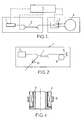
- the present invention relates to improvements brought to fiber optic ring gyros, which, as illustrated in FIG. 1 of the attached drawings, include a source of electromagnetic radiation 1 connected to a coupler 2 itself connected to a separator 3; the two branches of the separator 3 are connected respectively at the two ends of a ring guide constituted by a coil 4 of optical fiber which may have a diameter of at least 60 mm; how the gyrometer is provided by a connected electronic module 5 at source 1, at separator 3 and at the output of the coupler 2 where interference from counter propagating waves is detected having circulated in the coil 4.
- the invention is concerned with those of these gyrometers which are of interferometric type (IFOG) and which have high performances, in which the source 1 of electromagnetic radiation comprises, as illustrated in figure 2, a radiation generator electromagnetic 6 such as an LED diode, which is connected to a coupler 7 itself connected to a doped optical fiber 8, wound on several turns having a diameter of at least minus 60 mm, the free end of which is connected to a mirror 9; the output of the coupler 7 is connected, to through an optical diode 10, to the user (coupler 2 in Figure 1).
- a source of this type equipped with a fiber optical doped with erbium emits radiation having a wavelength close to 1.55 ⁇ m.
- the RL product and the factor ⁇ do not vary by the same amount with temperature, which induces a variation of the factor K s with temperature.
- the quantities R and L are parameters of the coil, whereas ⁇ is a parameter of the light source.
- the coil and the light source are physically separate from each other and can be separated from each other. As a result, they can be brought to different temperatures when the gyrometer is operating. Correcting the coefficient K s as a function of temperature would then require knowledge of two models (RL as a function of temperature, and ⁇ as a function of temperature) and two temperature values (that of the coil and that of the light source).
- the invention therefore aims to provide a original and simple solution that increases the precision of the gyrometer while implementing means simple and inexpensive that does not significantly affect the overall cost of the interferometric gyrometer.
- an interferometric gyrometer with high performance as mentioned above characterized, being arranged in accordance with the invention, in what the coil and the doped optical fiber are arranged in close proximity to each other and in contact thermal with each other.
- the optical fiber doped with the source is wound on the fiber coil and is in close thermal contact with it, and preferably it is rolled up on the middle region (middle of the height) of the coil so that the doped fiber is brought to the average temperature of the coil; preferably the doped optical fiber is wound externally to the middle region of the coil; advantageously she is wound in contiguous turns to obtain a optimal thermal uniformity.
- the fiber doped wound optics are glued to the coil, in particular with the same glue as that used to constitute the coil.
- the solution according to the invention proves to be particularly effective because it is the doped fiber from the source which induces the greatest variations in ⁇ with the temperature: now the doped fiber and the coil are approximately the same temperature and there is only one model to know (the quantity RL / ⁇ depending on the temperature).
- the solution according to the invention is revealed in economical because the assembly of the coil remains unchanged from the previous assembly: the coil is glued by its center on a metal support and a temperature sensor is fixed on this support. The assembly process and materials therefore do not need to be changed.
- the solution according to the invention incidentally leads to a substantial gain in space.
- optical fibers cannot be bent with radius of curvature too small (risk of breakage).
- the fiber optic coil of the interferometer has a diameter of around 70 mm and the doped fiber must not have radii of curvature less than 60 mm.
- these two fiber windings optics are relatively bulky and, being incorporated in two separate housings with related bodies respective, these boxes are installed side by side at their location of use by occupying an important place, whereas, in general, the space available for envisaged applications (missiles for example) is counted.
- the stability of the Sagnac coefficient as a function of temperature by producing the light source and / or the measurement coil ways such as scaling factor evolutions generated, due to temperature variations, by one and / or the other of these two components compensate for the less partially.
- Figure 3 shows a fiber optic ring interferometric gyrometer with high performance which retains the same components as the interferometric gyrometer of the prior art illustrated in Figures 1 and 2, these components being designated using the same reference numbers as in Figures 1 and 2.
- the optical fiber coil 4 of the interferometer and the doped fiber 8 are placed in the immediate vicinity l 'from each other and in thermal contact with each other.
- the simplest solution is, as illustrated in figure 4, to physically reunite the coil 4 and the doped fiber 8 and to wind said fiber doped 8 on coil 4 so that the transmission from one to the other is as easy and also total as possible.
- the doped fiber 8, wound on the coil be glued on it with the same glue as that joining the turns of the optical fiber of the coil.
- the doped fiber 8 is at the temperature coil average, it is expected to be rolled up on the middle or central region (middle of the height) of the coil.
- the easiest mounting in practice is to wrap the doped fiber around the middle region of the coil, that is to say outside of it.
- the doped fiber 8 is wound and glued around coil 4, then coil 4 mounted on a metal core 11 (for example aluminum) on which it is glued and a temperature sensor (not shown) is fixed on this core. The process of mounting the coil is not changed.
- the model is acquired with the gyrometer in operation.
- the optical head 12 (interferometric sub-assembly including the separator 3, the coil 4 and the doped fiber 8) is placed in a thermal enclosure at controllable temperature.
- the gyrometer is rotated with a predetermined speed, at the same time as the temperature is varied.
- the control means 5 measure, during a rotation, a voltage proportional to the Sagnac phase shift induced by the rotation.
- the speed of rotation being known, it is possible to associate a value of the coefficient K s with each temperature.
- the coefficients of the thermal model are placed in memory and, during operation, the value of the coefficient K s is corrected as a function of the temperature measured on the head optical. This improves the accuracy of the gyroscope.
Landscapes
- Physics & Mathematics (AREA)
- Engineering & Computer Science (AREA)
- Optics & Photonics (AREA)
- Electromagnetism (AREA)
- Power Engineering (AREA)
- General Physics & Mathematics (AREA)
- Radar, Positioning & Navigation (AREA)
- Remote Sensing (AREA)
- Gyroscopes (AREA)
Abstract
Description
- la figure 3 est un schéma synoptique illustrant un gyromètre interférométrique en anneau à fibre optique à hautes performances agencé conformément à l'invention ;
- la figure 4 est une vue schématique en coupe diamétrale d'un mode de réalisation préféré d'une partie du gyromètre de la figure 3.
Claims (8)
- Gyromètre interférométrique en anneau à fibre optique, comprenant une bobine de fibre optique (4), une source de rayonnement électromagnétique (1) qui comporte une fibre optique dopée (8) et qui est munie d'un séparateur pour envoyer dans la bobine (4) deux ondes contra-propagatives en provenance de la source (1), et un détecteur d'interférence (2) recevant les ondes contra-propagatives,
caractérisé en ce que la bobine (4) et la fibre optique dopée (8) sont disposées à proximité immédiate l'une de l'autre et en contact thermique l'une avec l'autre. - Gyromètre interférométrique selon la revendication 1, caractérisé en ce que la fibre optique dopée (8) de la source est enroulée sur la bobine de fibre (4) et est en contact thermique étroit avec celle-ci.
- Gyromètre interférométrique selon la revendication 2, caractérisé en ce que la fibre dopée (8) est enroulée sur la région médiane de la bobine (4).
- Gyromètre interférométrique selon la revendication 3, caractérisé en ce que la fibre optique dopée (8) est enroulée extérieurement à la région médiane de la bobine (4) .
- Gyromètre interférométrique selon l'une quelconque des revendications 2 à 4, caractérisé en ce que la fibre optique dopée (8) est enroulée à spires jointives.
- Gyromètre interférométrique selon l'une quelconque des revendications 2 à 5, caractérisé en ce que la fibre optique dopée (8) enroulée est collée sur la bobine (4).
- Gyromètre interférométrique en anneau à fibre optique, à haute performance, selon l'une quelconque des revendications précédentes, caractérisé en ce que la fibre optique (8) de la source (1) est dopée à l'erbium.
- Gyromètre interférométrique selon l'une quelconque des revendications précédentes, caractérisé en ce que la source lumineuse et/ou la bobine sont réalisées pour présenter de façons telles que les évolutions de facteur d'échelle générées, en raison de variations de la température, par l'un et/ou l'autre de ces composants se compensent au moins partiellement, ce grâce à quoi la variation du coefficient de Sagnac Ks en fonction de la température est réduite au moins partiellement.
Applications Claiming Priority (2)
| Application Number | Priority Date | Filing Date | Title |
|---|---|---|---|
| FR9913585A FR2800456B1 (fr) | 1999-10-29 | 1999-10-29 | Gyrometre en anneau a fibre optique, a hautes performances |
| FR9913585 | 1999-10-29 |
Publications (2)
| Publication Number | Publication Date |
|---|---|
| EP1096227A1 true EP1096227A1 (fr) | 2001-05-02 |
| EP1096227B1 EP1096227B1 (fr) | 2013-07-03 |
Family
ID=9551534
Family Applications (1)
| Application Number | Title | Priority Date | Filing Date |
|---|---|---|---|
| EP20000402953 Expired - Lifetime EP1096227B1 (fr) | 1999-10-29 | 2000-10-25 | Gyromètre interferometrique en anneau à fibre optique, à hautes performances |
Country Status (2)
| Country | Link |
|---|---|
| EP (1) | EP1096227B1 (fr) |
| FR (1) | FR2800456B1 (fr) |
Cited By (3)
| Publication number | Priority date | Publication date | Assignee | Title |
|---|---|---|---|---|
| CN101339093B (zh) * | 2008-08-29 | 2010-06-09 | 苏州光环科技有限公司 | 光纤陀螺用光纤环质量的测量方法及其装置 |
| WO2022028281A1 (fr) * | 2020-08-06 | 2022-02-10 | 大连理工大学 | Gyroscope à fibre optique interférométrique en lumière blanche basé sur une structure de polarisation de différence de chemin optique rhombique |
| CN116878479A (zh) * | 2023-09-06 | 2023-10-13 | 西安现代控制技术研究所 | 一种三自惯导用光纤陀螺仪 |
Citations (3)
| Publication number | Priority date | Publication date | Assignee | Title |
|---|---|---|---|---|
| US5394242A (en) | 1989-12-15 | 1995-02-28 | The Charles Stark Draper Laboratory, Inc. | Fiber optic resonant ring sensor and source |
| US5453836A (en) * | 1993-04-22 | 1995-09-26 | Agency For Defense Development | Fiber optic laser rotation sensor utilizing a fiber loop reflector |
| US5684590A (en) * | 1995-12-29 | 1997-11-04 | Honeywell Inc. | Fiber optic gyroscope source wavelength control |
-
1999
- 1999-10-29 FR FR9913585A patent/FR2800456B1/fr not_active Expired - Fee Related
-
2000
- 2000-10-25 EP EP20000402953 patent/EP1096227B1/fr not_active Expired - Lifetime
Patent Citations (3)
| Publication number | Priority date | Publication date | Assignee | Title |
|---|---|---|---|---|
| US5394242A (en) | 1989-12-15 | 1995-02-28 | The Charles Stark Draper Laboratory, Inc. | Fiber optic resonant ring sensor and source |
| US5453836A (en) * | 1993-04-22 | 1995-09-26 | Agency For Defense Development | Fiber optic laser rotation sensor utilizing a fiber loop reflector |
| US5684590A (en) * | 1995-12-29 | 1997-11-04 | Honeywell Inc. | Fiber optic gyroscope source wavelength control |
Cited By (5)
| Publication number | Priority date | Publication date | Assignee | Title |
|---|---|---|---|---|
| CN101339093B (zh) * | 2008-08-29 | 2010-06-09 | 苏州光环科技有限公司 | 光纤陀螺用光纤环质量的测量方法及其装置 |
| WO2022028281A1 (fr) * | 2020-08-06 | 2022-02-10 | 大连理工大学 | Gyroscope à fibre optique interférométrique en lumière blanche basé sur une structure de polarisation de différence de chemin optique rhombique |
| US11692827B2 (en) | 2020-08-06 | 2023-07-04 | Dalian University Of Technology | White light interferometric fiber-optic gyroscope based on rhombic optical path difference bias structure |
| CN116878479A (zh) * | 2023-09-06 | 2023-10-13 | 西安现代控制技术研究所 | 一种三自惯导用光纤陀螺仪 |
| CN116878479B (zh) * | 2023-09-06 | 2023-12-29 | 西安现代控制技术研究所 | 一种三自惯导用光纤陀螺仪 |
Also Published As
| Publication number | Publication date |
|---|---|
| FR2800456B1 (fr) | 2001-12-28 |
| EP1096227B1 (fr) | 2013-07-03 |
| FR2800456A1 (fr) | 2001-05-04 |
Similar Documents
| Publication | Publication Date | Title |
|---|---|---|
| EP0108671A1 (fr) | Dispositif de mesure de température et/ou d'intensité électrique à effet Faraday | |
| EP0033048A1 (fr) | Interféromètre à cavité optique accordable comprenant une fibre optique monomode et application au filtrage et à la spectrographie | |
| EP0079268A1 (fr) | Interferomètre de type Michelson à miroir photoréfractif | |
| WO2000049368A1 (fr) | Dispositif de detection de mouvement d'activation pour gyrolaser | |
| EP0656545B1 (fr) | Magnétomètre à polarisation lumineuse et à champ de radiofréquence couplés | |
| WO1994029674A1 (fr) | Capteur a fibre optique reconfigurable | |
| EP0806675A1 (fr) | Capteur de tension électro-optique à fibre optique | |
| EP1096227B1 (fr) | Gyromètre interferometrique en anneau à fibre optique, à hautes performances | |
| EP0018873B1 (fr) | Dispositif compact de couplage optique et gyromètre interferométrique à fibre optique comportant un tel dispositif | |
| WO2014096636A1 (fr) | Dispositif de mesure interférométrique comportant un interféromètre de filtrage | |
| EP0108012A1 (fr) | Dispositif de mesure d'intensité électrique à effet Faraday | |
| FR2828278A1 (fr) | Capteur de deplacement angulaire et son application dans une direction assistee pour vehicule automobile | |
| EP0077259A1 (fr) | Procédé et dispositif de mesure du diamètre effectif du mode guide dans une fibre optique monomode | |
| EP3666665B1 (fr) | Dispositif deployable avec controle de longueur deployee d'une structure deployable | |
| EP0943906B1 (fr) | Capteur d'effort à fibre optique, procédé de fabrication d'un tel capteur, et dispositif de détection d'effort utilisant ce capteur | |
| FR2765964A1 (fr) | Dispositif optique de mesure de distance avec une grande precision | |
| WO2022123182A1 (fr) | Dispositif de mesure de deplacement mecanique d'une piece | |
| EP0511119B1 (fr) | Capteur de vibrations à fibre optique et accéléromètre utilisant un tel capteur | |
| EP0938644B1 (fr) | Gyrometre a fibre optique multimode, a resolution et a stabilite ameliorees | |
| FR2643466A1 (fr) | Dispositif pour le controle et l'ajustement de l'alignement modal de fibres optiques | |
| EP0448415A1 (fr) | Dispositif de détection à distance d'une grandeur physique, fonctionnant en réflexion | |
| FR2647897A1 (fr) | Procede et capteur optique pour la determination de la position d'un corps mobile | |
| EP0591912B1 (fr) | Interféromètre, comprenant un ensemble intégré et un miroir séparés l'un de l'autre par une région de mesure | |
| EP1018636B1 (fr) | Gyroscope à fibre optique | |
| Ono et al. | A small-sized, compact, open-loop fibre-optic gyroscope with stabilised scale factor |
Legal Events
| Date | Code | Title | Description |
|---|---|---|---|
| PUAI | Public reference made under article 153(3) epc to a published international application that has entered the european phase |
Free format text: ORIGINAL CODE: 0009012 |
|
| AK | Designated contracting states |
Kind code of ref document: A1 Designated state(s): DE FR GB |
|
| AX | Request for extension of the european patent |
Free format text: AL;LT;LV;MK;RO;SI |
|
| 17P | Request for examination filed |
Effective date: 20010321 |
|
| AKX | Designation fees paid |
Free format text: DE FR GB |
|
| RAP1 | Party data changed (applicant data changed or rights of an application transferred) |
Owner name: SAGEM DEFENSE SECURITE |
|
| 17Q | First examination report despatched |
Effective date: 20080624 |
|
| GRAP | Despatch of communication of intention to grant a patent |
Free format text: ORIGINAL CODE: EPIDOSNIGR1 |
|
| GRAS | Grant fee paid |
Free format text: ORIGINAL CODE: EPIDOSNIGR3 |
|
| GRAA | (expected) grant |
Free format text: ORIGINAL CODE: 0009210 |
|
| AK | Designated contracting states |
Kind code of ref document: B1 Designated state(s): DE FR GB |
|
| REG | Reference to a national code |
Ref country code: GB Ref legal event code: FG4D Free format text: NOT ENGLISH |
|
| REG | Reference to a national code |
Ref country code: DE Ref legal event code: R096 Ref document number: 60048103 Country of ref document: DE Effective date: 20130829 |
|
| RAP2 | Party data changed (patent owner data changed or rights of a patent transferred) |
Owner name: SAGEM DEFENSE SECURITE |
|
| PLBE | No opposition filed within time limit |
Free format text: ORIGINAL CODE: 0009261 |
|
| STAA | Information on the status of an ep patent application or granted ep patent |
Free format text: STATUS: NO OPPOSITION FILED WITHIN TIME LIMIT |
|
| 26N | No opposition filed |
Effective date: 20140404 |
|
| REG | Reference to a national code |
Ref country code: DE Ref legal event code: R097 Ref document number: 60048103 Country of ref document: DE Effective date: 20140404 |
|
| REG | Reference to a national code |
Ref country code: FR Ref legal event code: CA Effective date: 20140805 |
|
| REG | Reference to a national code |
Ref country code: FR Ref legal event code: PLFP Year of fee payment: 16 |
|
| PGFP | Annual fee paid to national office [announced via postgrant information from national office to epo] |
Ref country code: GB Payment date: 20150924 Year of fee payment: 16 |
|
| PGFP | Annual fee paid to national office [announced via postgrant information from national office to epo] |
Ref country code: DE Payment date: 20150922 Year of fee payment: 16 |
|
| REG | Reference to a national code |
Ref country code: FR Ref legal event code: PLFP Year of fee payment: 17 |
|
| REG | Reference to a national code |
Ref country code: FR Ref legal event code: CD Owner name: SAGEM DEFENSE SECURITE, FR Effective date: 20170126 |
|
| REG | Reference to a national code |
Ref country code: DE Ref legal event code: R119 Ref document number: 60048103 Country of ref document: DE |
|
| GBPC | Gb: european patent ceased through non-payment of renewal fee |
Effective date: 20161025 |
|
| PG25 | Lapsed in a contracting state [announced via postgrant information from national office to epo] |
Ref country code: DE Free format text: LAPSE BECAUSE OF NON-PAYMENT OF DUE FEES Effective date: 20170503 Ref country code: GB Free format text: LAPSE BECAUSE OF NON-PAYMENT OF DUE FEES Effective date: 20161025 |
|
| REG | Reference to a national code |
Ref country code: FR Ref legal event code: PLFP Year of fee payment: 18 |
|
| REG | Reference to a national code |
Ref country code: FR Ref legal event code: PLFP Year of fee payment: 19 |
|
| PGFP | Annual fee paid to national office [announced via postgrant information from national office to epo] |
Ref country code: FR Payment date: 20190919 Year of fee payment: 20 |