EP1096302A1 - Projecteur a cristaux liquides - Google Patents
Projecteur a cristaux liquides Download PDFInfo
- Publication number
- EP1096302A1 EP1096302A1 EP99926939A EP99926939A EP1096302A1 EP 1096302 A1 EP1096302 A1 EP 1096302A1 EP 99926939 A EP99926939 A EP 99926939A EP 99926939 A EP99926939 A EP 99926939A EP 1096302 A1 EP1096302 A1 EP 1096302A1
- Authority
- EP
- European Patent Office
- Prior art keywords
- liquid crystal
- color range
- light
- layer
- dichroic
- Prior art date
- Legal status (The legal status is an assumption and is not a legal conclusion. Google has not performed a legal analysis and makes no representation as to the accuracy of the status listed.)
- Granted
Links
Images


Classifications
-
- H—ELECTRICITY
- H04—ELECTRIC COMMUNICATION TECHNIQUE
- H04N—PICTORIAL COMMUNICATION, e.g. TELEVISION
- H04N9/00—Details of colour television systems
- H04N9/12—Picture reproducers
- H04N9/31—Projection devices for colour picture display, e.g. using electronic spatial light modulators [ESLM]
- H04N9/3102—Projection devices for colour picture display, e.g. using electronic spatial light modulators [ESLM] using two-dimensional electronic spatial light modulators
- H04N9/3105—Projection devices for colour picture display, e.g. using electronic spatial light modulators [ESLM] using two-dimensional electronic spatial light modulators for displaying all colours simultaneously, e.g. by using two or more electronic spatial light modulators
-
- H—ELECTRICITY
- H04—ELECTRIC COMMUNICATION TECHNIQUE
- H04N—PICTORIAL COMMUNICATION, e.g. TELEVISION
- H04N9/00—Details of colour television systems
- H04N9/12—Picture reproducers
- H04N9/31—Projection devices for colour picture display, e.g. using electronic spatial light modulators [ESLM]
- H04N9/3141—Constructional details thereof
- H04N9/315—Modulator illumination systems
- H04N9/3167—Modulator illumination systems for polarizing the light beam
-
- G—PHYSICS
- G02—OPTICS
- G02F—OPTICAL DEVICES OR ARRANGEMENTS FOR THE CONTROL OF LIGHT BY MODIFICATION OF THE OPTICAL PROPERTIES OF THE MEDIA OF THE ELEMENTS INVOLVED THEREIN; NON-LINEAR OPTICS; FREQUENCY-CHANGING OF LIGHT; OPTICAL LOGIC ELEMENTS; OPTICAL ANALOGUE/DIGITAL CONVERTERS
- G02F1/00—Devices or arrangements for the control of the intensity, colour, phase, polarisation or direction of light arriving from an independent light source, e.g. switching, gating or modulating; Non-linear optics
- G02F1/01—Devices or arrangements for the control of the intensity, colour, phase, polarisation or direction of light arriving from an independent light source, e.g. switching, gating or modulating; Non-linear optics for the control of the intensity, phase, polarisation or colour
- G02F1/13—Devices or arrangements for the control of the intensity, colour, phase, polarisation or direction of light arriving from an independent light source, e.g. switching, gating or modulating; Non-linear optics for the control of the intensity, phase, polarisation or colour based on liquid crystals, e.g. single liquid crystal display cells
- G02F1/133—Constructional arrangements; Operation of liquid crystal cells; Circuit arrangements
- G02F1/1333—Constructional arrangements; Manufacturing methods
- G02F1/1335—Structural association of cells with optical devices, e.g. polarisers or reflectors
- G02F1/133528—Polarisers
- G02F1/133533—Colour selective polarisers
-
- H—ELECTRICITY
- H04—ELECTRIC COMMUNICATION TECHNIQUE
- H04N—PICTORIAL COMMUNICATION, e.g. TELEVISION
- H04N5/00—Details of television systems
- H04N5/74—Projection arrangements for image reproduction, e.g. using eidophor
- H04N5/7416—Projection arrangements for image reproduction, e.g. using eidophor involving the use of a spatial light modulator, e.g. a light valve, controlled by a video signal
- H04N5/7441—Projection arrangements for image reproduction, e.g. using eidophor involving the use of a spatial light modulator, e.g. a light valve, controlled by a video signal the modulator being an array of liquid crystal cells
Definitions
- the present invention relates to a liquid crystal projector device incorporating a reflection type liquid crystal panel designed for realizing a greater compactness by reducing the number of parts.
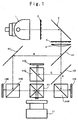
- the conventional liquid crystal projector device using the reflection type liquid crystal panel is designed so that, for example as shown in Fig.1, a white light from a light source 1 is condensed by lens arrays 2, 5 and a lens 6; the condensed light is separated into the lights for three colors coming within a red color range, a green color range and a blue color range respectively; s-polarized light components of the different color ranges are separated by polarizing beam splitters (PBS) 44R, 44G and 44B to incident on a reflection type liquid crystal panels for the ranges of red color, green color and blue color 10R, 10G and 10B respectively; image-forming lights having p-polarized light components of different color ranges, which have been modulated and reflected to be output, are synthesized by a cross dichroic prism 45 to be projected on a screen through a projection lens 11.
- PBS polarizing beam splitters
- the present invention was made in consideration of such problem and designed not only to reduce the dimensions of the device by providing an optical block having a dichroic reflection characteristic and a retarding characteristic so that the plane of polarization of the light ray of specified wavelength range can be rotated 90° the plane of polarization of the light ray of specified wavelength range to reduce the number of parts that results in the reduction of the dimensions of the device but also make the three reflection type liquid crystal panels compatible with one another by using a 1/2 retarding plate.
- the liquid crystal projector device of the present invention which is primarily designed so that the white light, coming from the light source, is separated into the lights of red color range, green color range and blue color range and polarized respectively; the separated and polarized light rays are made to incident on three pieces of reflection type liquid crystal panels for red color range, green color range and blue color range respectively; the image-forming lights modulated and reflected by the reflection type liquid crystal panels are synthesized for projection; wherein an optical unit designed for rotating 90° the plane of polarization of a specified light ray out of those of the three color ranges is provided so that either the light ray of a color range, whose plane of polarization has been rotated 90°, outputted from the optical unit or the light ray of a color range, whose plane of polarization has not been rotated, is made to incident on each of the reflection type liquid crystal panels.
- the optical unit comprises a first dichroic layer, which permits the transmission of the light ray of a specified color range and reflects the light rays of other color ranges, a retarding layer for rotating 90° the plane of polarization of the light ray, which is allowed to pass through the first dichroic layer, and a total reflection layer for totally reflecting the light ray from the retarding layer.
- the optical unit may comprise a second dichroic layer designed for transmitting the light ray of a specified color range while reflecting the light rays of other color ranges, the retarding layer, for rotating 90° the plane of polarization of the light rays which has passed through the second dichroic layer and third dichroic layer having a predetermined gradient dichroic characteristic for reflecting the light rays coming from the retarding layer so that the difference in dichroic characteristic resulting from the difference in the angle of incidence to the second dichroic layer owing to being unparallel of the incident light.
- a reflection unit comprising a dichroic layer having a dichroic characteristic similar to that of the first dichroic layer or the second dichroic layer, a transmission layer, which will not cause the phase difference corresponding to the above-mentioned retarding layer, and a total reflection layer is provided before the optical unit in order to correct the optical path difference occurring in the optical unit.
- the first dichroic layer for s-polarization or the second dichroic layer for the same is used for a high transmittance characteristic that contributes to an effective utilization of the light rays.
- a 1/2 retarding plate for rotating 90° the plane of polarization of incident light is provided before the reflection type liquid crystal panel, which is similar to other two reflection type liquid crystal panels, for receiving the light ray reflected by the first dichroic layer or the second dichroic layer, whereby the common reflection type liquid crystal panels can be used.
- a polarization beam splitter provided for reflecting a light ray of a color range whose plane of polarization is not rotated by the optical unit while transmitting the light rays of other two color ranges whose planes of polarization are rotated by 90° respectively, a dichroic prism provided for making the light ray of one color range reflected by the polarization beam splitter incident on one of the reflection type liquid crystal panels, while transmitting one light ray of one color range out of the two light rays which have passed through the polarization beam splitter and reflecting the other so that the two light rays of the two different color ranges incident on two reflection type liquid crystal panels respectively, and the image-forming light rays, which are modulated and reflected by the two reflection type liquid crystal panels, synthesized by the dichroic prism and reflected by the polarization beam splitter to be projected on a screen through a projection lens together with an image-forming light ray, which has passed through the polarization beam splitter and then modulated and reflected by the
- the first dichroic layer or the second dichroic layer is one for reflecting the light ray of green color range and capable of making the characteristic of the dichroic prism milder.
- Fig.2 shows the liquid crystal projector device as the first embodiment of the present invention, wherein 1 represents a light source of the white light using a metal halide lamp or the like; 2 and 5, lens arrays for condensing the white light from the light source 1; 3, a total reflection mirror; 4, a polarization beam splitter (hereinafter referred to as s-polarized light PBS) for outputting the s-polarized light components of the white light from the light source 1; 6, a condenser lens for further condensing the white light from the lens array 5; 7, an optical unit for converting the component of the light ray of specific color range, e.g., red color range or blue color range, out of the white light from the condenser lens from the s-polarized light component to the r-polarized light component for reflection; 8, a PBS for reflecting the s-polarized light component of the light rays from the optical unit while transmitting p-polarized light component; 9, a dichroic prism for transmitting
- the s-polarized light PBS 4 comprises accumulated sub-blocks 4b of the PBS, each being equal in surface width w and thickness d and formed into a parallelogram inclined at 45°, and 1/2 retarding plates 4f arranged on the output planes of every other sub-blocks 4b.
- the s-polarized light PBS 4 composed as described above is designed to output only the s-polarized components of the light by being arranged so that the light rays outputted from the lenses of lens array 2 are condensed by the sub-blocks 4b which are not provided with the 1/2 retarding plates 4f, while the sub-blocks 4b with the 1/2 retarding plates prevent the incidence of light rays.
- the p-polarized light component is transmitted while the s-polarize component is reflected at the inclined boundary planes of the sub-blocks 4b.
- the plane of polarization of the transmitted p-polarized light component is converted into the plane of polarization of the s-polarized light component for output by the effect of the 1/2 retarding plate 4f.
- the reflected s-polarized light component is again reflected for output at the boundary planes of the sub-blocks 4b. In this way, only the s-polarized light components of light rays are permitted to passing through the s-polarized light PBS 4.
- the lens array 2 When the lens array 2 is arranged so that the outputs of the light therefrom are condensed by the sub-blocks 4b provided with the 1/2 retarding plates 4f, the p-polarized component which has passed through the boundary plane is outputted directly, while the s-polarized light components reflected by the boundary plane are reflected again to be converted into the p-polarized light components with respect to their planes of polarization, for being output. In this way, all the light rays passing through the s-polarized light PBS 4 are converted into the p-polarized light components.
- the white light, as naturally polarized light, from the light source 1 is condensed by two sets of lens arrays 2 and 5, having a total reflection mirror 3 and s-polarized light PBS 4 interposed in between respectively, and a condenser lens 6 to incident on an optical unit 7.
- the optical unit 7, as shown in Fig.4, is formed by accumulating a first dichroic layer 7a, a retarding layer 7b and a total reflection layer 7c, wherein, for example, the first dichroic layer 7a reflects the light of green color range while transmitting the light of blue color range and the light of red color range, and the retarding layer 7b rotates 90° the planes of polarization of the lights of the blue color range and red color range, which have passed through the first dichroic layer, while being reflected by the total reflection layer 7c (a total reflection mirror) for emission.
- the first dichroic layer 7a reflects the light of green color range while transmitting the light of blue color range and the light of red color range
- the retarding layer 7b rotates 90° the planes of polarization of the lights of the blue color range and red color range, which have passed through the first dichroic layer, while being reflected by the total reflection layer 7c (a total reflection mirror) for emission.
- the retarding layer 7b is a retarding plate that keeps unrotated the plane of polarization of the light of the green color range, while rotating 90° the planes of rotation of the lights of the blue color range and the red color range.
- the characteristic (dichroic characteristic) of the subsequent dichroic prism for separating the light of blue color range and the light of the red color range is set a mild level, the interference of the light incident on the reflection type liquid crystal panel 10B for the blue color range and the light incident on that for the red color range will not interfere with each other because of their wavelength ranges being sufficiently differentiated from each other.
- the light of blue color range is reflected by the dichroic prism 9 to incident on the reflection type liquid crystal panel 10B for blue color range to output the s-polarized image-forming light modulated by the blue color video signal.
- the light of red color range passes through the dichroic prism 9 to incident on the reflection type liquid crystal panel 10R for red color range to output s-polarized image-forming light modulated by the red color video signal.
- These image-forming lights of blue color range and red color range are synthesized by the dichroic prism and reflected by the PBS 8 to be projected on the screen through the projection lens 11 together with the image-forming light for green color range coming from the reflection type liquid crystal panel 10G passing through the PBS 8.
- the reflection type liquid crystal panel 10B for blue color range may be provided on the opposite side to the projection lens 11.
- a space sufficient for easy mounting the flange for the projection lens 11 can be provided between the projection lens 11 and the reflection type liquid crystal panel 10B.
- Fig.6 shows another example of the optical unit 7 designed to correct the difference in dichroic characteristic resulting from the difference in the angle of incidence (angle of incidence a ⁇ b ⁇ c) to the dichroic layer due to unparallel incident light rays.
- the dichroic layer has a characteristic that the smaller the incident angle, the longer the cut-off wavelength of the transmitting light ray and the shorter the cut-off wavelength of the reflected light ray. That is, as shown in Fig.6, at incident angle a, the cut-off wavelength of the transmitting light ray is longer than that at incident angle b (in terms of optical axis), while the cut-off wavelength of the reflected light ray becomes longer.
- the optical unit 7' comprises the second dichroic layer 7a', whose dichroic characteristic is inclined in the direction an arrow A, for transmitting the light rays of blue color range and red color range while reflecting the light ray of green color range, the retarding layer 7b, for rotating 90° the plane of polarization of the light ray that has passed through the second dichroic layer 7a', and the third dichroic layer 7c', whose dichroic characteristic for reflecting the light ray coming from the retarding layer 7b is inclined in the direction of an arrow A, whereby the characteristic of the dichroic layer (for cut-off wavelength) is continuously varied for correction.
- the reason for that the characteristic of the dichroic layer is inclined in the direction of the arrow is due to that, there is no significant difference in the incident angles at both ends (at front end and rear end in the figure) where the (optical unit 7') is perpendicular to the optical axes of the incident light rays, but, since the optical unit 7' is actually inclined 45° to the optical axis, there occurs a large difference in the incident angle due to that there occurs a difference in picture width (the difference between the upper left-hand end and the lower right-hand end), which is about 1.4 times (inverse sine 45°) the picture width where (the optical unit 7') is kept level.
- the differences in characteristic of both the dichroic layers due to the angle of incidence of the light ray can be corrected separately, and, simultaneously, the unnecessary components of the light ray which has passed through the second dichroic layer 7a can be omitted by letting them pass through the third dichroic layer 7c'.
- Fig.7 shows the liquid crystal projector device as a second embodiment of the present invention.
- the total reflection mirror 3 shown in Fig.2 is replaced with a reflection unit 31, which is provided before the optical unit 7 (or 7'). This is because of the necessity of correcting the disagreement of the irradiation areas resulting from the difference in the optical path between the light ray reflected by the first dichroic layer 7a of the optical unit 7 and the light ray reflected by the total reflection layer 7c.
- the reflection unit 31, as shown in Fig.8, comprises a dichroic layer 31a, having a characteristic similar to that of the first dichroic layer 7a (or the second dichroic layer 7a'), a transmitting layer 31b (a layer not producing phase difference), having a thickness equivalent to that of the retarding layer 7b, and a total reflection layer 31c.
- the light rays s' (the lights of blue color range and red color range), reflected by the total reflection layer 31c of the reflection unit 31, are made to be reflected by the total reflection layer 7c (or the third dichroic layer 7c') of the optical unit 7 (or 7')(to become a light rays p') whose optical paths substantially coincide with the optical path of the light ray s (a light ray of green color range), reflected by the dichroic layer 31a and the first dichroic layer 7a (or the second dichroic layer 7a'), so that the disagreement of the irradiation areas of the reflection type liquid crystal panels will not occur.
- the explanation of the numerals and symbols similar to those given in Fig.2 will be omitted here.
- s-polarized light PBS 4 is designed to transmit the s-polarized light component, and the dichroic layer 7a or 7a' for s-polarized light are provided on the surface of the optical unit 7a or 7a', because, as seen from Fig.9, the transmittance characteristic of the dichroic film (layer) varies depending on whether the transmitting light ray is the s-polarized light ray or the p-polarized light ray, and the transmittance of the light ray which has passed the retarding layer 7b, i.e., the p-polarized light ray, becomes high when the wavelength is within the range of about 380 nm or less and about 780 nm or more, entailing the rise of utilization rate of the wavelength range and resultant increase in the brightness of the projected picture. Further, since the s-polarized light PBS 4 transmits the s-polarized light, the dichroic layer for s-polarized light is also used with the reflection unit.
- the 1/2 retarding plate may be provided before the reflection type liquid crystal panel 10G for green color range in order to rotate 90° the plane of polarization of the s-polarized light ray for conversion into a p-polarized light ray, thereby enabling the p-polarized light incidence type reflection type liquid crystal panel, similar to the reflection type liquid crystal panels 10B and 10R, to be used as the reflection type liquid crystal panel 10G for making these three reflection type liquid crystal panels compatible with one another. Further, the s-polarized image-forming light, modulated and reflected by the reflection type liquid crystal panel 10G, is converted into a p-polarized light by the 1/2 retarding plate to pass through the PBS 8.
- the present invention is designed to take advantage of a reflection unit (an optical unit), comprising a dichroic layer, a retarding layer and a total reflection layer (or a dichroic layer) and having a dichroic characteristic and a retarding characteristic, to reduce the number of relatively costly PBS's, thereby providing a liquid crystal projector device featuring a lower cost and a smaller dimensions.
- a reflection unit an optical unit
- a dichroic layer comprising a dichroic layer, a retarding layer and a total reflection layer (or a dichroic layer) and having a dichroic characteristic and a retarding characteristic
Landscapes
- Engineering & Computer Science (AREA)
- Multimedia (AREA)
- Signal Processing (AREA)
- Liquid Crystal (AREA)
- Projection Apparatus (AREA)
- Video Image Reproduction Devices For Color Tv Systems (AREA)
- Transforming Electric Information Into Light Information (AREA)
Applications Claiming Priority (3)
| Application Number | Priority Date | Filing Date | Title |
|---|---|---|---|
| JP18835098A JP3573190B2 (ja) | 1998-07-03 | 1998-07-03 | 液晶プロジェクタ装置 |
| JP18835098 | 1998-07-03 | ||
| PCT/JP1999/003624 WO2000002084A1 (fr) | 1998-07-03 | 1999-07-05 | Projecteur a cristaux liquides |
Publications (3)
| Publication Number | Publication Date |
|---|---|
| EP1096302A1 true EP1096302A1 (fr) | 2001-05-02 |
| EP1096302A4 EP1096302A4 (fr) | 2003-01-29 |
| EP1096302B1 EP1096302B1 (fr) | 2005-02-02 |
Family
ID=16222096
Family Applications (1)
| Application Number | Title | Priority Date | Filing Date |
|---|---|---|---|
| EP99926939A Expired - Lifetime EP1096302B1 (fr) | 1998-07-03 | 1999-07-05 | Projecteur a cristaux liquides |
Country Status (6)
| Country | Link |
|---|---|
| US (1) | US6742897B1 (fr) |
| EP (1) | EP1096302B1 (fr) |
| JP (1) | JP3573190B2 (fr) |
| CA (1) | CA2336553C (fr) |
| DE (1) | DE69923561T2 (fr) |
| WO (1) | WO2000002084A1 (fr) |
Cited By (3)
| Publication number | Priority date | Publication date | Assignee | Title |
|---|---|---|---|---|
| US6995917B1 (en) * | 1999-04-08 | 2006-02-07 | Sharp Laboratories Of America, Inc. | Projection display system using polarized light |
| WO2011059879A1 (fr) * | 2009-11-11 | 2011-05-19 | Eastman Kodak Company | Combinateur de faisceaux à films minces et à compensation de phase |
| CN102377937A (zh) * | 2010-08-04 | 2012-03-14 | 株式会社日立国际电气 | 摄像装置 |
Families Citing this family (13)
| Publication number | Priority date | Publication date | Assignee | Title |
|---|---|---|---|---|
| US6550919B1 (en) * | 1999-03-26 | 2003-04-22 | Unaxis Balzers Aktiengesellschaft | Spectral light division and recombination configuration as well as process for the spectrally selective modulation of light |
| US6781640B1 (en) | 1999-11-15 | 2004-08-24 | Sharp Laboratories Of America, Inc. | Projection display having polarization compensator |
| US7101047B2 (en) | 2000-03-31 | 2006-09-05 | Sharp Laboratories Of America, Inc. | Projection display systems for light valves |
| JP3768381B2 (ja) * | 2000-05-11 | 2006-04-19 | 株式会社日立製作所 | 液晶プロジェクタ |
| JP4210425B2 (ja) * | 2000-12-08 | 2009-01-21 | 富士フイルム株式会社 | 光学素子 |
| US6739724B2 (en) | 2001-06-22 | 2004-05-25 | Seiko Epson Corporation | Illumination optical system and projector |
| JP2006145837A (ja) * | 2004-11-19 | 2006-06-08 | Nagano Kogaku Kenkyusho:Kk | 液晶プロジェクタ |
| JP4732089B2 (ja) | 2005-09-13 | 2011-07-27 | キヤノン株式会社 | 波長選択性偏光変換素子、投射表示光学系および画像投射装置 |
| JP2007163597A (ja) * | 2005-12-09 | 2007-06-28 | Canon Inc | 波長選択性偏光変換素子、照明光学系、投射表示光学系および画像投射装置 |
| US7821713B2 (en) * | 2007-05-18 | 2010-10-26 | 3M Innovative Properties Company | Color light combining system for optical projector |
| JP6043228B2 (ja) * | 2013-04-05 | 2016-12-14 | 浜松ホトニクス株式会社 | 光学モジュールおよび光照射装置 |
| JP6014538B2 (ja) * | 2013-04-05 | 2016-10-25 | 浜松ホトニクス株式会社 | 光学モジュール、光観察装置、及び光照射装置 |
| JP6014537B2 (ja) * | 2013-04-05 | 2016-10-25 | 浜松ホトニクス株式会社 | 光学モジュールおよび観察装置 |
Family Cites Families (17)
| Publication number | Priority date | Publication date | Assignee | Title |
|---|---|---|---|---|
| US5115305A (en) * | 1990-07-05 | 1992-05-19 | Baur Thomas G | Electrically addressable liquid crystal projection system with high efficiency and light output |
| JP2575558Y2 (ja) * | 1990-12-26 | 1998-07-02 | エルジー電子株式会社 | 液晶投写形ディスプレイの光学系構造 |
| JPH05323262A (ja) * | 1992-05-22 | 1993-12-07 | Fujitsu Ltd | 投写型液晶表示装置 |
| US5374968A (en) * | 1993-11-08 | 1994-12-20 | Greyhawk Systems, Inc. | Optics for a single-lens video projector with color-specific polarization channels |
| WO1996020422A1 (fr) * | 1994-12-28 | 1996-07-04 | Seiko Epson Corporation | Appareil d'eclairage en lumiere polarisee et dispositif d'affichage du type a projection |
| US6183091B1 (en) * | 1995-04-07 | 2001-02-06 | Colorlink, Inc. | Color imaging systems and methods |
| TW412656B (en) * | 1996-04-26 | 2000-11-21 | Hitachi Ltd | Liquid crystal display |
| JPH10142712A (ja) * | 1996-11-13 | 1998-05-29 | Matsushita Electric Ind Co Ltd | 投写型表示装置 |
| JP3444521B2 (ja) * | 1997-06-20 | 2003-09-08 | シャープ株式会社 | 投影型画像表示装置 |
| US6176586B1 (en) * | 1998-03-24 | 2001-01-23 | Minolta Co., Ltd. | Projection display apparatus |
| TW407222B (en) * | 1998-05-14 | 2000-10-01 | Primax Electronics Ltd | The projective display apparatus used to show the image |
| JP3622500B2 (ja) * | 1998-05-20 | 2005-02-23 | 株式会社富士通ゼネラル | 液晶プロジェクタ装置 |
| US6023370A (en) * | 1998-05-29 | 2000-02-08 | Primax Electronics Ltd. | Light polarizing device for generating a polarized light with different polarizations |
| JP3555451B2 (ja) * | 1998-06-22 | 2004-08-18 | ミノルタ株式会社 | 偏光変換ダイクロイックミラーと液晶プロジェクター |
| JP2000180792A (ja) * | 1998-12-10 | 2000-06-30 | Minolta Co Ltd | 照明光学系および投射型画像表示装置 |
| JP2001100155A (ja) * | 1999-09-30 | 2001-04-13 | Fujitsu General Ltd | 反射型液晶プロジェクタ |
| US6375330B1 (en) * | 1999-12-30 | 2002-04-23 | Gain Micro-Optics, Inc. | Reflective liquid-crystal-on-silicon projection engine architecture |
-
1998
- 1998-07-03 JP JP18835098A patent/JP3573190B2/ja not_active Expired - Fee Related
-
1999
- 1999-07-05 EP EP99926939A patent/EP1096302B1/fr not_active Expired - Lifetime
- 1999-07-05 US US09/720,234 patent/US6742897B1/en not_active Expired - Fee Related
- 1999-07-05 WO PCT/JP1999/003624 patent/WO2000002084A1/fr not_active Ceased
- 1999-07-05 CA CA002336553A patent/CA2336553C/fr not_active Expired - Fee Related
- 1999-07-05 DE DE69923561T patent/DE69923561T2/de not_active Expired - Fee Related
Cited By (4)
| Publication number | Priority date | Publication date | Assignee | Title |
|---|---|---|---|---|
| US6995917B1 (en) * | 1999-04-08 | 2006-02-07 | Sharp Laboratories Of America, Inc. | Projection display system using polarized light |
| WO2011059879A1 (fr) * | 2009-11-11 | 2011-05-19 | Eastman Kodak Company | Combinateur de faisceaux à films minces et à compensation de phase |
| US8305502B2 (en) | 2009-11-11 | 2012-11-06 | Eastman Kodak Company | Phase-compensated thin-film beam combiner |
| CN102377937A (zh) * | 2010-08-04 | 2012-03-14 | 株式会社日立国际电气 | 摄像装置 |
Also Published As
| Publication number | Publication date |
|---|---|
| CA2336553A1 (fr) | 2000-01-13 |
| JP3573190B2 (ja) | 2004-10-06 |
| EP1096302A4 (fr) | 2003-01-29 |
| DE69923561D1 (de) | 2005-03-10 |
| WO2000002084A1 (fr) | 2000-01-13 |
| CA2336553C (fr) | 2007-01-09 |
| EP1096302B1 (fr) | 2005-02-02 |
| DE69923561T2 (de) | 2005-08-04 |
| JP2000019455A (ja) | 2000-01-21 |
| US6742897B1 (en) | 2004-06-01 |
Similar Documents
| Publication | Publication Date | Title |
|---|---|---|
| JP3622500B2 (ja) | 液晶プロジェクタ装置 | |
| US6490087B1 (en) | Optical systems for reflective LCD's | |
| US5374968A (en) | Optics for a single-lens video projector with color-specific polarization channels | |
| JP3154691B2 (ja) | 投射装置 | |
| JP2951858B2 (ja) | 投影型カラー液晶表示装置 | |
| EP1096302B1 (fr) | Projecteur a cristaux liquides | |
| WO2001073485A1 (fr) | Ensemble prisme a rendement eleve pour projection d'images | |
| KR20060012613A (ko) | 고성능 단일 패널 및 두 개의 패널 투영 엔진 | |
| JP2001154268A (ja) | 光学エンジン及びそれを用いた液晶プロジェクタ | |
| JP3858723B2 (ja) | 光学ユニット及びそれを用いた投射型プロジェクタ装置 | |
| US20070216869A1 (en) | Projection type image display apparatus | |
| US6869184B2 (en) | Polarized-light converting unit and projector using the same | |
| JP2002131750A (ja) | 投写型表示装置 | |
| US7303283B2 (en) | Projection type display | |
| EP1762882B1 (fr) | Séparateur de faisceaux polarisant sélectif en longueur d'onde | |
| JPH0756167A (ja) | 偏光光源装置及びそれを用いた投写型液晶表示装置 | |
| JP3437035B2 (ja) | 単一偏光変換素子及び投射型表示装置 | |
| JP2674021B2 (ja) | 液晶プロジエクタ | |
| JPH11352478A (ja) | 液晶プロジェクタ装置 | |
| JP3659209B2 (ja) | 光学ユニット及びそれを用いた映像表示装置 | |
| JPH10161255A (ja) | 投写形液晶表示装置および液晶パネル | |
| JP5084041B2 (ja) | 投射型表示装置 | |
| JP2004012864A (ja) | 投射型画像表示装置 | |
| JP2004061599A (ja) | プロジェクタ | |
| JPH09261677A (ja) | 背面投写型液晶プロジェクタ装置 |
Legal Events
| Date | Code | Title | Description |
|---|---|---|---|
| PUAI | Public reference made under article 153(3) epc to a published international application that has entered the european phase |
Free format text: ORIGINAL CODE: 0009012 |
|
| 17P | Request for examination filed |
Effective date: 20010124 |
|
| AK | Designated contracting states |
Kind code of ref document: A1 Designated state(s): AT BE CH CY DE DK ES FI FR GB GR IE IT LI LU MC NL PT SE |
|
| A4 | Supplementary search report drawn up and despatched |
Effective date: 20021213 |
|
| RIC1 | Information provided on ipc code assigned before grant |
Ipc: 7H 04N 9/31 B Ipc: 7G 02F 1/1335 A |
|
| 17Q | First examination report despatched |
Effective date: 20030411 |
|
| GRAP | Despatch of communication of intention to grant a patent |
Free format text: ORIGINAL CODE: EPIDOSNIGR1 |
|
| RBV | Designated contracting states (corrected) |
Designated state(s): DE FR GB IT NL |
|
| GRAS | Grant fee paid |
Free format text: ORIGINAL CODE: EPIDOSNIGR3 |
|
| GRAA | (expected) grant |
Free format text: ORIGINAL CODE: 0009210 |
|
| AK | Designated contracting states |
Kind code of ref document: B1 Designated state(s): DE FR GB IT NL |
|
| PG25 | Lapsed in a contracting state [announced via postgrant information from national office to epo] |
Ref country code: IT Free format text: LAPSE BECAUSE OF FAILURE TO SUBMIT A TRANSLATION OF THE DESCRIPTION OR TO PAY THE FEE WITHIN THE PRESCRIBED TIME-LIMIT;WARNING: LAPSES OF ITALIAN PATENTS WITH EFFECTIVE DATE BEFORE 2007 MAY HAVE OCCURRED AT ANY TIME BEFORE 2007. THE CORRECT EFFECTIVE DATE MAY BE DIFFERENT FROM THE ONE RECORDED. Effective date: 20050202 |
|
| REG | Reference to a national code |
Ref country code: GB Ref legal event code: FG4D |
|
| REG | Reference to a national code |
Ref country code: IE Ref legal event code: FG4D |
|
| REF | Corresponds to: |
Ref document number: 69923561 Country of ref document: DE Date of ref document: 20050310 Kind code of ref document: P |
|
| PLBE | No opposition filed within time limit |
Free format text: ORIGINAL CODE: 0009261 |
|
| STAA | Information on the status of an ep patent application or granted ep patent |
Free format text: STATUS: NO OPPOSITION FILED WITHIN TIME LIMIT |
|
| ET | Fr: translation filed | ||
| 26N | No opposition filed |
Effective date: 20051103 |
|
| PGFP | Annual fee paid to national office [announced via postgrant information from national office to epo] |
Ref country code: DE Payment date: 20060629 Year of fee payment: 8 |
|
| PGFP | Annual fee paid to national office [announced via postgrant information from national office to epo] |
Ref country code: NL Payment date: 20060703 Year of fee payment: 8 |
|
| PGFP | Annual fee paid to national office [announced via postgrant information from national office to epo] |
Ref country code: GB Payment date: 20060705 Year of fee payment: 8 |
|
| PGFP | Annual fee paid to national office [announced via postgrant information from national office to epo] |
Ref country code: FR Payment date: 20060719 Year of fee payment: 8 |
|
| GBPC | Gb: european patent ceased through non-payment of renewal fee |
Effective date: 20070705 |
|
| NLV4 | Nl: lapsed or anulled due to non-payment of the annual fee |
Effective date: 20080201 |
|
| PG25 | Lapsed in a contracting state [announced via postgrant information from national office to epo] |
Ref country code: NL Free format text: LAPSE BECAUSE OF NON-PAYMENT OF DUE FEES Effective date: 20080201 Ref country code: DE Free format text: LAPSE BECAUSE OF NON-PAYMENT OF DUE FEES Effective date: 20080201 |
|
| PG25 | Lapsed in a contracting state [announced via postgrant information from national office to epo] |
Ref country code: GB Free format text: LAPSE BECAUSE OF NON-PAYMENT OF DUE FEES Effective date: 20070705 |
|
| REG | Reference to a national code |
Ref country code: FR Ref legal event code: ST Effective date: 20080331 |
|
| PG25 | Lapsed in a contracting state [announced via postgrant information from national office to epo] |
Ref country code: FR Free format text: LAPSE BECAUSE OF NON-PAYMENT OF DUE FEES Effective date: 20070731 |