EP1096354A2 - Wasser-Durchflussregler - Google Patents
Wasser-Durchflussregler Download PDFInfo
- Publication number
- EP1096354A2 EP1096354A2 EP00610111A EP00610111A EP1096354A2 EP 1096354 A2 EP1096354 A2 EP 1096354A2 EP 00610111 A EP00610111 A EP 00610111A EP 00610111 A EP00610111 A EP 00610111A EP 1096354 A2 EP1096354 A2 EP 1096354A2
- Authority
- EP
- European Patent Office
- Prior art keywords
- valve
- regulator
- pressure
- chamber
- piston
- Prior art date
- Legal status (The legal status is an assumption and is not a legal conclusion. Google has not performed a legal analysis and makes no representation as to the accuracy of the status listed.)
- Granted
Links
Images

Classifications
-
- F—MECHANICAL ENGINEERING; LIGHTING; HEATING; WEAPONS; BLASTING
- F16—ENGINEERING ELEMENTS AND UNITS; GENERAL MEASURES FOR PRODUCING AND MAINTAINING EFFECTIVE FUNCTIONING OF MACHINES OR INSTALLATIONS; THERMAL INSULATION IN GENERAL
- F16K—VALVES; TAPS; COCKS; ACTUATING-FLOATS; DEVICES FOR VENTING OR AERATING
- F16K31/00—Actuating devices; Operating means; Releasing devices
- F16K31/002—Actuating devices; Operating means; Releasing devices actuated by temperature variation
-
- G—PHYSICS
- G05—CONTROLLING; REGULATING
- G05D—SYSTEMS FOR CONTROLLING OR REGULATING NON-ELECTRIC VARIABLES
- G05D16/00—Control of fluid pressure
- G05D16/028—Controlling a pressure difference
-
- G—PHYSICS
- G05—CONTROLLING; REGULATING
- G05D—SYSTEMS FOR CONTROLLING OR REGULATING NON-ELECTRIC VARIABLES
- G05D16/00—Control of fluid pressure
- G05D16/04—Control of fluid pressure without auxiliary power
- G05D16/06—Control of fluid pressure without auxiliary power the sensing element being a flexible membrane, yielding to pressure, e.g. diaphragm, bellows, capsule
- G05D16/063—Control of fluid pressure without auxiliary power the sensing element being a flexible membrane, yielding to pressure, e.g. diaphragm, bellows, capsule the sensing element being a membrane
- G05D16/0644—Control of fluid pressure without auxiliary power the sensing element being a flexible membrane, yielding to pressure, e.g. diaphragm, bellows, capsule the sensing element being a membrane the membrane acting directly on the obturator
- G05D16/0655—Control of fluid pressure without auxiliary power the sensing element being a flexible membrane, yielding to pressure, e.g. diaphragm, bellows, capsule the sensing element being a membrane the membrane acting directly on the obturator using one spring-loaded membrane
-
- G—PHYSICS
- G05—CONTROLLING; REGULATING
- G05D—SYSTEMS FOR CONTROLLING OR REGULATING NON-ELECTRIC VARIABLES
- G05D23/00—Control of temperature
- G05D23/01—Control of temperature without auxiliary power
- G05D23/12—Control of temperature without auxiliary power with sensing element responsive to pressure or volume changes in a confined fluid
- G05D23/125—Control of temperature without auxiliary power with sensing element responsive to pressure or volume changes in a confined fluid the sensing element being placed outside a regulating fluid flow
- G05D23/126—Control of temperature without auxiliary power with sensing element responsive to pressure or volume changes in a confined fluid the sensing element being placed outside a regulating fluid flow using a capillary tube
Definitions
- the invention relates to a water regulator comprising a thermostatically controlled and a pressure controlled regulating unit, and where the thermostatically controlled unit comprises a sensor device and a valve device, said devices being connected via a capillary tube in such a manner that through the liquid pressure in the device the temperature around the sensor device will actuate the valve in the valve device and thereby the supply of the medium to be regulated by the sensor device.
- Regulators of this kind are used wherever a hot medium such as a district heating is used for heating purposes and where an automatic regulation of the supply of this medium and hence the temperature is desired.
- DOS 23 37 861 describing a thermostatic regulating valve based on a direct transmission of the expansion or contraction of a liquid by heating and cooling, respectively.
- a built-in safety function which may partly ensure against excess pressure and partly ensure that the valve adjusts itself to a predetermined position in case of a failure of the effect of the sensor liquid.
- US 3,917,164 describes a thermostatic regulating valve combined with a differential pressure regulator and furthermore with a combined humidity sensor and humidifier.
- the object of this regulator is to ensure a constant flow through the thermostatic valve at a given temperature and to automatically control the humidity from a heating/cooling surface.
- the capillary tube opens into a piston chamber in the valve device housing, the valve spindle in said chamber being arranged in such a manner that a pressure change within the piston chamber will move the spindle and thus a valve body mounted thereon relative to a valve seat of the valve, and that the pressure controlled unit comprises a further valve seat, which seat is arranged in the outlet opening of the valve seat of the regulator, and where a valve body may regulate the circulation of the heating medium independently of the position of the valve body of the regulator.
- a regulator is thereby obtained which can be used for regulating district heating installations, wherein the differential pressure is normally high, as well as hot water installations of any type in that the thermostatic regulating valve is combined with a pressure controlled valve which is controlled by the pressure drop occurring when a second independent water flow flows through a special pressure control module.
- This valve may therefore quite independently of temperature variations turn on and shut off the liquid flow.
- a regulator has accordingly been provided which can fit into all existing installations in that the regulator is adjustable according to installation and operational conditions.
- the regulator operates as a kind of all-purpose regulator resulting in substantial savings and at the same time a great simplification to the fitter who will only have to use a single type for different installations.
- an adjustable piston chamber volume by means of an externally adjustable piston, it is possible to achieve the desired limitation of the temperature range of the regulator.
- the spring By mounting the adjustable piston with a compression spring, as disclosed in claim 3, the spring power thereof retaining the piston within the chamber, the spring will operate as a safety spring in the event that a foreign body blocks the valve action. The same will be the case if a maladjustment of the regulator has been made. This will prevent overloading or perhaps bursting of the valve housing.
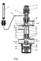
- Figs. 1 and 2 show examples of the regulator according to the invention.
- the pressure controlled regulator 21 is mounted as a valve with a valve housing 23 cooperating with a valve seat 22, which is placed opposite the thermostatically controlled valve 7, 9.
- the regulator operates as a combined regulator combining the advantages of a pressure controlled regulator and a thermostatically controlled regulator.
- the thermostat In periods of state where the heat exchanger is cold, the thermostat is fully open, but since the pressure control regulator 21 is closed, there is no circulation of the heating medium 20.
- the thermostatic valve 1, 3, 5, 7 ,13 and 17 of the regulator When hot water is not drawn off, the thermostatic valve 1, 3, 5, 7 ,13 and 17 of the regulator is open corresponding to the hot water temperature at the remote sensor 1 of the thermostat, whereas the pressure controlled part 23, 30, 34, 35, 36, 37, 38, 39 and 40 of the regulator is closed.
- the cold water slide valve 39 is not designed to keep tight so that the cold water pressure from the supply side of the cold water part may seep past the cold water slide valve 39 until the pressure on either side of the roller diaphragm 40 is equal. Subsequently, the compression spring will ensure that the roller diaphragm 40 and the cold water slide valve 39 is pressed back. This will ensure that the pressure cone 23 of the district heating part 31 is completely shut off.
- the cold water slide valve 39 is mounted on the spindle 30 together with the roller diaphragm 40, and at the other end of the spindle 30 the pressure cone 23 of the district heating part 31 is mounted.
- the cold water chamber 37 and the district heating chamber 28 are separated by two stuffing boxes 32 having a bored discharge 41 to the surroundings therebetween. This will ensure that a defective stuffing box 32 will not cause cold water and district heating water being mixed.
- the pressure cone 23 of the district heating part 31 will open for district heating circulation.
- the thermostatic valve 1, 3, 5, 7, 13 and 17 of the district heating part 31 will subsequently take over the control of the hot water temperature.
- the thermostatic valve 1, 3, 5, 7, 13 and 17 operates such that an increasing temperature in the remote sensor 1 makes the thermostatic cone 23 close against the seat 9, and a decreasing temperature in the remote sensor 1 makes the thermostatic cone 23 withdraw itself from the seat 9 and thereby open for district heating circulation.
- the thermostat starts to regulate such that the heating medium and the drawing off temperature are kept at the desired level irrespective of the drawing off volume.
- the sensor 1 cools off relatively quickly after the drawing off, depending of course on the temperature of the surroundings, but after a short period of time the thermostat is cool and the thermostat will then be open.
- the regulator since the regulator only allows district heating water to flow through the district heating part 31 of the regulator when hot water is drawn off, it may be necessary to provide the regulator with a by-pass function ensuring that the district heating supply pipe does not get cold since the waiting time for hot water is thereby unnecessarily prolonged. This may take place outside the regulator by providing a thermostatically controlled "short circuit" of the supply and outlet pipes of the district heating.
- This solution may, if desired, be fitted with a temperature regulation so that the by-pass temperature may be adjusted independently of the predetermined hot water temperature.
- Provision of by-pass may also take place by providing the regulator with a bore from the district heating supply pipe stub 29 and past the district heating pressure cone 23 into the chamber 27 in the district heating seat 9 between pressure cone 23 and thermostat cone 7 or perhaps by making a small bore in the district heating pressure cone 23 itself. No matter which of these two solutions are chosen, the temperature of the by-pass function will be controlled by the thermostatic valve of the regulator and the temperature therefore depends on the predetermined hot water temperature.
- a third solution may be to provide internally between the district heating supply pipe stub 29 and the district heating outlet pipe stub 26 of the regulator a small thermostatically controlled by-pass which, if so desired, may be provided with a temperature regulation.
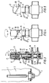
- the thermostatic unit comprises, as shown in fig. 3, a housing 5 wherein adjustment equipment has been mounted at the top and valve equipment at the bottom.
- the valve equipment comprises a valve body 7 cooperating with a valve seat 9 and thereby the circulation of the heat medium 20 to be regulated.
- valve body 7 is mounted on a spindle 6 which is slidable in an axially controlled manner in a packing 24 having a compression spring 8 between the free end of the spindle and the packing 24. This spring 8 maintains the valve body 7 in an open valve position.
- the free part of the spindle 6 extends into a chamber 4 into which a capillary tube 3 of a sensor unit opens.
- the sensor unit 1 is in the usual manner filled with liquid and the temperature conditions regulate the flow of liquid into the piston chamber in a generally known manner.
- the volume of the chamber 4 may be adjusted by means of an adjustment piston 10, the position of which within the chamber 4 may be varied.
- the screw 12 with piston 10 is slidable out of the chamber 4 against the spring power of a compression spring 14 in such a manner that any excess pressure within the chamber will make the piston 10 slide against the spring power.
- This device will accordingly operate as a safety device and prevent damage to the regulator which would at worst mean a burst of the housing 5.
- the object thereof is to be capable of restricting the movement of the pin 17 by means of a guide or a slide track 18, which is designed on a sleeve 15.
- This sleeve 15 operates as a scale tube in that externally thereof there are provided marks 19 for the position of the pin 17 in such a manner that this device may be used for adjustment of the temperature interval of the regulator.
- the sleeve 15 is slidably arranged on the housing 5 and can be retained in the desired position by means of a locking screw 16.
- Fig. 1 accordingly shows a position wherein the sleeve 15 is in its middle position allowing a 180° turn of the handle 13.
- the adjustment of the regulator takes place in the following manner.
- the desired temperature is achieved by turning the adjustment handle 13 by either limiting or locking which takes place by sliding the sleeve tube 15 on the housing. This takes place by loosening the screw 16 on the lateral side of the sleeve tube and turning the sleeve to the desired position and then tighten the screw.
- Limitation of a desired temperature interval takes place in a similar manner by sliding the sleeve tube 15 axially in its highest position, fig. 3, locking the adjustment handle 13 since the marking pin 17 is wedged in between two bevelled edges of the sleeve tube 15.
- the adjustment handle 13 can be turned about 180° whereas in its lowest position, fig. 2, it can be turned about 360°.
- the thermostat may advantageously be used for many different types of regulation in heating and hot water installations, for example floor heating installations, bathing installations etc.
- thermostatic valve 1, 3, 5, 7, 13 and 17 may if desired alternatively be replaced by an electronically controlled valve engine with spindle and cone thereby achieving an electronic control of the hot water temperature.
Landscapes
- Physics & Mathematics (AREA)
- Engineering & Computer Science (AREA)
- Fluid Mechanics (AREA)
- General Physics & Mathematics (AREA)
- Automation & Control Theory (AREA)
- General Engineering & Computer Science (AREA)
- Mechanical Engineering (AREA)
- Control Of Fluid Pressure (AREA)
- Temperature-Responsive Valves (AREA)
- Magnetically Actuated Valves (AREA)
Applications Claiming Priority (2)
| Application Number | Priority Date | Filing Date | Title |
|---|---|---|---|
| DK155199 | 1999-10-29 | ||
| DKPA199901551 | 1999-10-29 |
Publications (3)
| Publication Number | Publication Date |
|---|---|
| EP1096354A2 true EP1096354A2 (de) | 2001-05-02 |
| EP1096354A3 EP1096354A3 (de) | 2002-06-05 |
| EP1096354B1 EP1096354B1 (de) | 2005-11-30 |
Family
ID=8105989
Family Applications (1)
| Application Number | Title | Priority Date | Filing Date |
|---|---|---|---|
| EP00610111A Expired - Lifetime EP1096354B1 (de) | 1999-10-29 | 2000-10-27 | Wasser-Durchflussregler |
Country Status (3)
| Country | Link |
|---|---|
| EP (1) | EP1096354B1 (de) |
| AT (1) | ATE311626T1 (de) |
| DE (2) | DE29923039U1 (de) |
Cited By (7)
| Publication number | Priority date | Publication date | Assignee | Title |
|---|---|---|---|---|
| EP1422451A1 (de) * | 2002-11-20 | 2004-05-26 | Honeywell Ag | Ventilbaugruppe |
| WO2008089501A1 (de) | 2007-01-25 | 2008-07-31 | Herz Armaturen Ges.M.B.H. | Vorrichtung zur regelung der temperatur von brauchwasser |
| DE102009041799A1 (de) | 2009-08-17 | 2011-02-24 | Robert Bosch Gmbh | Schaltventil und Sicherheitssystem und Armatur |
| RU2455548C1 (ru) * | 2011-04-11 | 2012-07-10 | Аванян Эдуард Александрович | Регулятор расхода жидкости |
| EP2642170A1 (de) | 2012-03-21 | 2013-09-25 | Fugas Spa | Regler für Haushaltswasserdurchfluss und hydraulische Einheit damit |
| WO2018071947A1 (de) | 2016-10-20 | 2018-04-26 | Herz Armaturen Ges.M.B.H. | Vorrichtung zur regelung der temperatur von brauchwasser |
| CN113091120A (zh) * | 2021-04-15 | 2021-07-09 | 方靖 | 一种供热系统自力式温差平衡调节装置 |
Family Cites Families (3)
| Publication number | Priority date | Publication date | Assignee | Title |
|---|---|---|---|---|
| US2733865A (en) * | 1956-02-07 | ehlke | ||
| US2752931A (en) * | 1953-08-31 | 1956-07-03 | Penn Controls | Automatic shut-off for regulator valves and the like |
| US3294321A (en) * | 1964-02-21 | 1966-12-27 | Dole Valve Co | Zone thermostatic valve with multiple movable seats |
-
1999
- 1999-12-30 DE DE29923039U patent/DE29923039U1/de not_active Expired - Lifetime
-
2000
- 2000-10-27 EP EP00610111A patent/EP1096354B1/de not_active Expired - Lifetime
- 2000-10-27 DE DE60024396T patent/DE60024396D1/de not_active Expired - Lifetime
- 2000-10-27 AT AT00610111T patent/ATE311626T1/de active
Cited By (9)
| Publication number | Priority date | Publication date | Assignee | Title |
|---|---|---|---|---|
| EP1422451A1 (de) * | 2002-11-20 | 2004-05-26 | Honeywell Ag | Ventilbaugruppe |
| WO2008089501A1 (de) | 2007-01-25 | 2008-07-31 | Herz Armaturen Ges.M.B.H. | Vorrichtung zur regelung der temperatur von brauchwasser |
| RU2429424C2 (ru) * | 2007-01-25 | 2011-09-20 | Херц Арматурен Гез.М.Б.Х. | Устройство для регулирования температуры технической воды |
| DE102009041799A1 (de) | 2009-08-17 | 2011-02-24 | Robert Bosch Gmbh | Schaltventil und Sicherheitssystem und Armatur |
| RU2455548C1 (ru) * | 2011-04-11 | 2012-07-10 | Аванян Эдуард Александрович | Регулятор расхода жидкости |
| EP2642170A1 (de) | 2012-03-21 | 2013-09-25 | Fugas Spa | Regler für Haushaltswasserdurchfluss und hydraulische Einheit damit |
| WO2018071947A1 (de) | 2016-10-20 | 2018-04-26 | Herz Armaturen Ges.M.B.H. | Vorrichtung zur regelung der temperatur von brauchwasser |
| CN113091120A (zh) * | 2021-04-15 | 2021-07-09 | 方靖 | 一种供热系统自力式温差平衡调节装置 |
| CN113091120B (zh) * | 2021-04-15 | 2022-04-12 | 方靖 | 一种供热系统自力式温差平衡调节装置 |
Also Published As
| Publication number | Publication date |
|---|---|
| DE29923039U1 (de) | 2000-04-27 |
| EP1096354B1 (de) | 2005-11-30 |
| ATE311626T1 (de) | 2005-12-15 |
| DE60024396D1 (de) | 2006-01-05 |
| EP1096354A3 (de) | 2002-06-05 |
Similar Documents
| Publication | Publication Date | Title |
|---|---|---|
| US5623990A (en) | Temperature-controlled water delivery system | |
| US5148976A (en) | Thermostatic mixing valve | |
| US5323803A (en) | Instant hot water device | |
| CA2401988C (en) | Mixing valve | |
| CA2290913C (en) | Tempered water mixing system | |
| AU697940B2 (en) | A thermostatic faucet mixing valve | |
| US6575377B1 (en) | Mixing valve | |
| US6508406B1 (en) | Fail-safe proportional mixing valve | |
| AU2001241781A1 (en) | Mixing valve | |
| US4475684A (en) | Mixing valve | |
| CA2140466A1 (en) | Hydronic heating outdoor temperature reset supply water temperature control system | |
| GB2127529A (en) | Hot water heating installation | |
| RU2508510C1 (ru) | Система регулирования распределения текучей среды | |
| EP1096354B1 (de) | Wasser-Durchflussregler | |
| EP0448315A2 (de) | Thermostatisches Mischventil | |
| GB2265476A (en) | Hot water supply controller | |
| US20030052181A1 (en) | Supplemental hot water heat for forced air furnaces | |
| GB2306631A (en) | Domestic water heating apparatus | |
| DK200000320U3 (da) | Vandregulator | |
| PL176277B1 (pl) | Urządzenie do regulacji temperatury wody w instalacji wodnej | |
| US7343928B2 (en) | Regulator insert with hydraulic damping in outlet | |
| AU767118B2 (en) | Fail-safe proportional mixing valve | |
| JPS6051627B2 (ja) | 冷房給湯装置 | |
| JPS6145349Y2 (de) | ||
| US4346567A (en) | Heat pump control valve |
Legal Events
| Date | Code | Title | Description |
|---|---|---|---|
| PUAI | Public reference made under article 153(3) epc to a published international application that has entered the european phase |
Free format text: ORIGINAL CODE: 0009012 |
|
| AK | Designated contracting states |
Kind code of ref document: A2 Designated state(s): AT BE CH CY DE DK ES FI FR GB GR IE IT LI LU MC NL PT SE |
|
| AX | Request for extension of the european patent |
Free format text: AL;LT;LV;MK;RO;SI |
|
| PUAL | Search report despatched |
Free format text: ORIGINAL CODE: 0009013 |
|
| AK | Designated contracting states |
Kind code of ref document: A3 Designated state(s): AT BE CH CY DE DK ES FI FR GB GR IE IT LI LU MC NL PT SE |
|
| AX | Request for extension of the european patent |
Free format text: AL;LT;LV;MK;RO;SI |
|
| 17P | Request for examination filed |
Effective date: 20021205 |
|
| AKX | Designation fees paid |
Designated state(s): AT BE CH CY DE DK ES FI FR GB GR IE IT LI LU MC NL PT SE |
|
| AXX | Extension fees paid |
Extension state: LT Payment date: 20021205 Extension state: SI Payment date: 20021205 Extension state: MK Payment date: 20021205 Extension state: RO Payment date: 20021205 Extension state: LV Payment date: 20021205 Extension state: AL Payment date: 20021205 |
|
| RAP1 | Party data changed (applicant data changed or rights of an application transferred) |
Owner name: DANFOSS REDAN A/S |
|
| 17Q | First examination report despatched |
Effective date: 20041104 |
|
| GRAP | Despatch of communication of intention to grant a patent |
Free format text: ORIGINAL CODE: EPIDOSNIGR1 |
|
| GRAS | Grant fee paid |
Free format text: ORIGINAL CODE: EPIDOSNIGR3 |
|
| GRAA | (expected) grant |
Free format text: ORIGINAL CODE: 0009210 |
|
| AK | Designated contracting states |
Kind code of ref document: B1 Designated state(s): AT BE CH CY DE DK ES FI FR GB GR IE IT LI LU MC NL PT SE |
|
| AX | Request for extension of the european patent |
Extension state: AL LT LV MK RO SI |
|
| PG25 | Lapsed in a contracting state [announced via postgrant information from national office to epo] |
Ref country code: BE Free format text: LAPSE BECAUSE OF FAILURE TO SUBMIT A TRANSLATION OF THE DESCRIPTION OR TO PAY THE FEE WITHIN THE PRESCRIBED TIME-LIMIT Effective date: 20051130 Ref country code: CH Free format text: LAPSE BECAUSE OF FAILURE TO SUBMIT A TRANSLATION OF THE DESCRIPTION OR TO PAY THE FEE WITHIN THE PRESCRIBED TIME-LIMIT Effective date: 20051130 Ref country code: FI Free format text: LAPSE BECAUSE OF FAILURE TO SUBMIT A TRANSLATION OF THE DESCRIPTION OR TO PAY THE FEE WITHIN THE PRESCRIBED TIME-LIMIT Effective date: 20051130 Ref country code: LI Free format text: LAPSE BECAUSE OF FAILURE TO SUBMIT A TRANSLATION OF THE DESCRIPTION OR TO PAY THE FEE WITHIN THE PRESCRIBED TIME-LIMIT Effective date: 20051130 |
|
| REG | Reference to a national code |
Ref country code: CH Ref legal event code: EP Ref country code: GB Ref legal event code: FG4D |
|
| REG | Reference to a national code |
Ref country code: IE Ref legal event code: FG4D |
|
| REF | Corresponds to: |
Ref document number: 60024396 Country of ref document: DE Date of ref document: 20060105 Kind code of ref document: P |
|
| PG25 | Lapsed in a contracting state [announced via postgrant information from national office to epo] |
Ref country code: GR Free format text: LAPSE BECAUSE OF FAILURE TO SUBMIT A TRANSLATION OF THE DESCRIPTION OR TO PAY THE FEE WITHIN THE PRESCRIBED TIME-LIMIT Effective date: 20060228 Ref country code: DK Free format text: LAPSE BECAUSE OF FAILURE TO SUBMIT A TRANSLATION OF THE DESCRIPTION OR TO PAY THE FEE WITHIN THE PRESCRIBED TIME-LIMIT Effective date: 20060228 |
|
| REG | Reference to a national code |
Ref country code: SE Ref legal event code: TRGR |
|
| PG25 | Lapsed in a contracting state [announced via postgrant information from national office to epo] |
Ref country code: DE Free format text: LAPSE BECAUSE OF FAILURE TO SUBMIT A TRANSLATION OF THE DESCRIPTION OR TO PAY THE FEE WITHIN THE PRESCRIBED TIME-LIMIT Effective date: 20060301 |
|
| PG25 | Lapsed in a contracting state [announced via postgrant information from national office to epo] |
Ref country code: ES Free format text: LAPSE BECAUSE OF FAILURE TO SUBMIT A TRANSLATION OF THE DESCRIPTION OR TO PAY THE FEE WITHIN THE PRESCRIBED TIME-LIMIT Effective date: 20060313 |
|
| PG25 | Lapsed in a contracting state [announced via postgrant information from national office to epo] |
Ref country code: PT Free format text: LAPSE BECAUSE OF FAILURE TO SUBMIT A TRANSLATION OF THE DESCRIPTION OR TO PAY THE FEE WITHIN THE PRESCRIBED TIME-LIMIT Effective date: 20060502 |
|
| LTIE | Lt: invalidation of european patent or patent extension |
Effective date: 20051130 |
|
| REG | Reference to a national code |
Ref country code: CH Ref legal event code: PL |
|
| PLBE | No opposition filed within time limit |
Free format text: ORIGINAL CODE: 0009261 |
|
| STAA | Information on the status of an ep patent application or granted ep patent |
Free format text: STATUS: NO OPPOSITION FILED WITHIN TIME LIMIT |
|
| PG25 | Lapsed in a contracting state [announced via postgrant information from national office to epo] |
Ref country code: IE Free format text: LAPSE BECAUSE OF NON-PAYMENT OF DUE FEES Effective date: 20061027 |
|
| PG25 | Lapsed in a contracting state [announced via postgrant information from national office to epo] |
Ref country code: MC Free format text: LAPSE BECAUSE OF NON-PAYMENT OF DUE FEES Effective date: 20061031 |
|
| 26N | No opposition filed |
Effective date: 20060831 |
|
| EN | Fr: translation not filed | ||
| GBPC | Gb: european patent ceased through non-payment of renewal fee |
Effective date: 20061027 |
|
| REG | Reference to a national code |
Ref country code: IE Ref legal event code: MM4A |
|
| PG25 | Lapsed in a contracting state [announced via postgrant information from national office to epo] |
Ref country code: GB Free format text: LAPSE BECAUSE OF NON-PAYMENT OF DUE FEES Effective date: 20061027 |
|
| PG25 | Lapsed in a contracting state [announced via postgrant information from national office to epo] |
Ref country code: FR Free format text: LAPSE BECAUSE OF FAILURE TO SUBMIT A TRANSLATION OF THE DESCRIPTION OR TO PAY THE FEE WITHIN THE PRESCRIBED TIME-LIMIT Effective date: 20070119 |
|
| PG25 | Lapsed in a contracting state [announced via postgrant information from national office to epo] |
Ref country code: LU Free format text: LAPSE BECAUSE OF NON-PAYMENT OF DUE FEES Effective date: 20061027 |
|
| PG25 | Lapsed in a contracting state [announced via postgrant information from national office to epo] |
Ref country code: FR Free format text: LAPSE BECAUSE OF FAILURE TO SUBMIT A TRANSLATION OF THE DESCRIPTION OR TO PAY THE FEE WITHIN THE PRESCRIBED TIME-LIMIT Effective date: 20051130 Ref country code: CY Free format text: LAPSE BECAUSE OF FAILURE TO SUBMIT A TRANSLATION OF THE DESCRIPTION OR TO PAY THE FEE WITHIN THE PRESCRIBED TIME-LIMIT Effective date: 20051130 |
|
| PGFP | Annual fee paid to national office [announced via postgrant information from national office to epo] |
Ref country code: NL Payment date: 20191014 Year of fee payment: 20 Ref country code: SE Payment date: 20191010 Year of fee payment: 20 |
|
| PGFP | Annual fee paid to national office [announced via postgrant information from national office to epo] |
Ref country code: IT Payment date: 20191009 Year of fee payment: 20 |
|
| PGFP | Annual fee paid to national office [announced via postgrant information from national office to epo] |
Ref country code: AT Payment date: 20190925 Year of fee payment: 20 |
|
| REG | Reference to a national code |
Ref country code: NL Ref legal event code: MK Effective date: 20201026 |
|
| REG | Reference to a national code |
Ref country code: AT Ref legal event code: MK07 Ref document number: 311626 Country of ref document: AT Kind code of ref document: T Effective date: 20201027 |