EP1096355A2 - Agencement de pédale dans un véhicule automobile - Google Patents
Agencement de pédale dans un véhicule automobile Download PDFInfo
- Publication number
- EP1096355A2 EP1096355A2 EP00119399A EP00119399A EP1096355A2 EP 1096355 A2 EP1096355 A2 EP 1096355A2 EP 00119399 A EP00119399 A EP 00119399A EP 00119399 A EP00119399 A EP 00119399A EP 1096355 A2 EP1096355 A2 EP 1096355A2
- Authority
- EP
- European Patent Office
- Prior art keywords
- pedal
- carriage
- clutch
- arrangement according
- driver
- Prior art date
- Legal status (The legal status is an assumption and is not a legal conclusion. Google has not performed a legal analysis and makes no representation as to the accuracy of the status listed.)
- Withdrawn
Links
Images

Classifications
-
- G—PHYSICS
- G05—CONTROLLING; REGULATING
- G05G—CONTROL DEVICES OR SYSTEMS INSOFAR AS CHARACTERISED BY MECHANICAL FEATURES ONLY
- G05G1/00—Controlling members, e.g. knobs or handles; Assemblies or arrangements thereof; Indicating position of controlling members
- G05G1/30—Controlling members actuated by foot
- G05G1/40—Controlling members actuated by foot adjustable
- G05G1/405—Controlling members actuated by foot adjustable infinitely adjustable
-
- B—PERFORMING OPERATIONS; TRANSPORTING
- B60—VEHICLES IN GENERAL
- B60K—ARRANGEMENT OR MOUNTING OF PROPULSION UNITS OR OF TRANSMISSIONS IN VEHICLES; ARRANGEMENT OR MOUNTING OF PLURAL DIVERSE PRIME-MOVERS IN VEHICLES; AUXILIARY DRIVES FOR VEHICLES; INSTRUMENTATION OR DASHBOARDS FOR VEHICLES; ARRANGEMENTS IN CONNECTION WITH COOLING, AIR INTAKE, GAS EXHAUST OR FUEL SUPPLY OF PROPULSION UNITS IN VEHICLES
- B60K23/00—Arrangement or mounting of control devices for vehicle transmissions, or parts thereof, not otherwise provided for
- B60K23/02—Arrangement or mounting of control devices for vehicle transmissions, or parts thereof, not otherwise provided for for main transmission clutches
-
- B—PERFORMING OPERATIONS; TRANSPORTING
- B60—VEHICLES IN GENERAL
- B60K—ARRANGEMENT OR MOUNTING OF PROPULSION UNITS OR OF TRANSMISSIONS IN VEHICLES; ARRANGEMENT OR MOUNTING OF PLURAL DIVERSE PRIME-MOVERS IN VEHICLES; AUXILIARY DRIVES FOR VEHICLES; INSTRUMENTATION OR DASHBOARDS FOR VEHICLES; ARRANGEMENTS IN CONNECTION WITH COOLING, AIR INTAKE, GAS EXHAUST OR FUEL SUPPLY OF PROPULSION UNITS IN VEHICLES
- B60K26/00—Arrangement or mounting of propulsion-unit control devices in vehicles
- B60K26/02—Arrangement or mounting of propulsion-unit control devices in vehicles of initiating means or elements
Definitions
- the invention relates to a pedal arrangement for motor vehicles with one in one Pedal slidable to hold a pedal to operate a Actuating device, for example a master brake cylinder, one Clutch master cylinder, a clutch bowden cable or a throttle cable, the Motor vehicle.
- a Actuating device for example a master brake cylinder, one Clutch master cylinder, a clutch bowden cable or a throttle cable, the Motor vehicle.
- pedal arrangement is known from EP 0 471 791 D1, EP 0 363 546 A1 or EP 0 265 466 A2 known.
- the known from these publications Common to pedal arrangements is that the pedal is pivotable on a carriage is mounted, which is driven by a spindle drive in the vehicle longitudinal direction towards the driver or can be moved away from the driver. The point is to get the pedal closer to a small one Position the driver closer or farther away from a large driver, so that driver different ergonomic seating positions in the vehicle can take. Small drivers often have to adjust the vehicle seat very far move the front to the pedals usually rigidly arranged in the vehicle to be able to achieve.
- a disadvantage of the aforementioned devices is that one by the pedal operating actuator, for example a master brake cylinder Clutch master cylinder, a clutch bowden cable, a throttle cable or the like Devices that are stored on the bulkhead. So it is in the in the beginning mentioned writings shown examples of a brake pedal a brake pressure rod designed to be variable in length to actuate the master brake cylinder, each to Length of the brake pressure rod to the distance of the brake pedal from the bulkhead adjust.
- a Bowden cable for the throttle cable of that shown in EP 0 363 546 A1 For example, has a jacket that is held at one end on the bulkhead.
- the wire of the Bowden cable is attached to the accelerator pedal via a deflection disc, the Deflection plate can be moved together with the accelerator pedal in such a way that the free length of the wire in the rest position is constant with any pedal position.
- the invention is based on the problem of having a pedal arrangement to create slidable pedals that is easy and inexpensive to manufacture and which reduces the risk of injury to the driver in the event of a traffic accident is.
- the pedal arrangement according to the invention is thereby to solve this problem characterized in that the actuating device also on the displaceable Sledge is held.
- the actuating device for example the Master brake cylinder, the clutch master cylinder, the clutch bowden cable, the Throttle cable or similar device, with the pedal on a common, slidable sled held.
- the actuator is also common proceed with the sledge.
- the relative position of the actuator and pedal is thus unchanged at every pedal position, so that a structurally simpler pedal attachment is guaranteed.
- the measure according to the invention For example, brake cylinder decoupled from the bulkhead, so that at one Bulkhead intrusion due to a traffic accident an additional pivoting of the Brake pedal to the driver did not take place.
- the survival space for the driver is in the Foot area is therefore not reduced, so that the risk of injury is reduced.
- an accelerator pedal, a Brake pedal and, if applicable, as far as it is not related to motor vehicles Automatic transmission acts a clutch pedal can be arranged.
- a footrest is also attached to the sled. Accelerator pedal, brake pedal and if necessary, the clutch pedal and footrest can be shared by the driver be moved so that the effort for adjusting the pedal positions is reduced.
- a spindle drive or a pressure medium cylinder for example a Hydraulic cylinders or a pneumatic cylinder can be used.
- a spindle drive or a pressure medium cylinder for example a Hydraulic cylinders or a pneumatic cylinder.
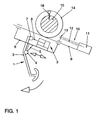
- Fig. 1 shows the example of a pedal arrangement for a pedal 1, which here is a clutch or Brake pedal can be, which with a cylinder 2, the corresponding here Clutch master cylinder or a master brake cylinder cooperates.
- the pedal 1 has a two-armed lever 3, which on a hinge 4 and a web 5 Carriage 6 is mounted. At its upper free end, the lever 3 of the pedal 1 is over a joint 7 is connected to a push rod 8 for actuating the cylinder 2.
- the carriage 6 is slidably mounted on a guide 9.
- the guide 9 extends towards the driver at an angle downwards and in the vehicle's longitudinal direction. This will also the carriage 6 is shifted approximately in the longitudinal direction of the vehicle. This takes place in present case via a spindle drive 10, one by a motor 11 to their Has longitudinal spindle rotatable threaded spindle 12, which in turn with a spindle nut 13 cooperates on the slide 6.
- a spindle drive 10 one by a motor 11 to their Has longitudinal spindle rotatable threaded spindle 12, which in turn with a spindle nut 13 cooperates on the slide 6.
- there is also one Pressure medium cylinder unit for example by a hydraulic cylinder or Pneumatic cylinder, for moving the slide 6 possible.
- the cylinder 2 is also attached to the carriage 6 and is thus together with move pedal 1. Relative position of pedal 1 and cylinder 2 thus change not, so that a length compensation or the like of the push rod 8 is omitted.
- the guide 9 is attached to a tubular sleeve 14 in the present case a cross tube 15 is mounted.
- a shear pin 16 prevents the sleeve 14 and so that the guide 9 rotates relative to the cross tube 15.
- the shear pin 16 is like this designed that he increased when acting on the pedal 1 due to a traffic accident Foot force shears off, so that the sleeve 14 rotates with respect to the cross tube 15 can.
- the pedal 1 becomes a due to the foot force away from the driver Bulkhead pivoted.
- the survival space for the driver in the Increases foot area and thus reduces the risk of injury.
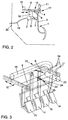
- the pedal 1 has a one-armed Lever 3, which is mounted at its upper end via a joint 4 on a carriage 6 is.
- a push rod 8 is attached to the lever 3 via a joint 7 and actuates one Cylinder 2, which in turn can be a master brake cylinder or a clutch master cylinder can.
- the carriage 6 is in turn movably mounted on a guide 9 which is fixed on a cross tube 15 is attached.
- a spindle drive 10 again serves for the movement, which can be driven by a motor 11 by means of a bevel gear 17.
- Alternatives are here again hydraulic or pneumatic pressure medium cylinders are conceivable.
- the cylinder 2 is also on the carriage 6 via a holder 18 stored so that the master cylinder 2 together with the pedal 1 by the Carriage 6 can be moved along the guide 9.
- 2 is another one Hydraulic line 19 recognizable for the clutch or brake system.
- the Hydraulic line 19 is flexible and passed through a bulkhead 20. Depending on The distance of the cylinder 2 from the bulkhead 20 can be the hydraulic line 19 deform due to their flexibility.
- FIG. 3 shows an example in which an accelerator pedal 1 a, a brake pedal 1 b Clutch pedal 1c and a footrest 21 mounted on a common carriage 6 are.
- the carriage 6 can be moved in the longitudinal direction of the vehicle via two spindle drives 10. Furthermore, the carriage 6 serves as an abutment for a clutch bowden cable 22, one Dual-circuit master brake cylinder 23 and a throttle cable (not shown).
- the Master brake cylinder 23 in turn has flexible hydraulic lines 19 that pass through the bulkhead are led to the braking system.
- the Bowden cables for the Clutch Bowden cable 22 and the throttle cable are flexible per se.
- a wire 24 of the clutch cable 22 is through passed the carriage 6 while a jacket 25 of the coupling bowden cable 22nd is attached to the carriage 6.
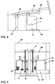
- FIGS. 4 and 5 The embodiment shown in FIGS. 4 and 5 is in accordance with the embodiment Fig. 3 very similar.
- the main difference is that the pedals 1 here are additionally arranged in a common cage 26.
- the cage 26 is on two Threaded spindles 12 arranged parallel to one another can be moved. These are on yours front, the bulkhead 20 facing end mounted on a support 27, which also is secured by a cross tube 28. On their front, facing the driver At the end, the threaded spindles 12 are rotatably supported in a further cross tube 29.
- the cage 26 can be closed at the bottom by a base plate 35, so that when Moving the cage 26 also raises or lowers the bottom of the same.
- the high of Base plate 35 is also matched to the body size of the driver. So is one Lifting the base plate 35 advantageous for small drivers.
- the threaded spindles 12 are parallel to one in the embodiment shown Steering column 30, namely slightly rising towards the driver. This will also the cage 26 is slightly raised towards the driver when moving. Alternatively, you can the threaded spindles 12 but also any other orientation to the steering column 30, for example, an exactly horizontal course or a slope falling towards the driver Course.
- Actuators such as a master cylinder Clutch master cylinders, a clutch bowden cable or a throttle cable are in the 5 and 6 for the sake of simplifying the drawing omitted. However, they are analogous to the exemplary embodiment according to FIG. 3 on one Rear wall 31 of the cage 26 attached.
- the exemplary embodiment according to FIGS. 6 and 7 also shows a pedal arrangement in the one Accelerator pedal 1a, a brake pedal 1b, a clutch pedal 1c and a footrest 21 a common carriage 6 are held.
- the carriage 6 is an in here Transverse longitudinally movable cross tube, which on a vehicle outer wall 32 and a center tunnel 33 can be moved in a guide 34.
- actuating devices in Fig. 7 specifically a master cylinder 2, attached and together with the pedals 1 movable.
Landscapes
- Engineering & Computer Science (AREA)
- Chemical & Material Sciences (AREA)
- Combustion & Propulsion (AREA)
- Transportation (AREA)
- Mechanical Engineering (AREA)
- Physics & Mathematics (AREA)
- General Physics & Mathematics (AREA)
- Automation & Control Theory (AREA)
- Mechanical Control Devices (AREA)
- Braking Elements And Transmission Devices (AREA)
- Arrangement And Mounting Of Devices That Control Transmission Of Motive Force (AREA)
Applications Claiming Priority (2)
| Application Number | Priority Date | Filing Date | Title |
|---|---|---|---|
| DE1999152228 DE19952228B4 (de) | 1999-10-29 | 1999-10-29 | Pedalanordnung für Kraftfahrzeuge |
| DE19952228 | 1999-10-29 |
Publications (2)
| Publication Number | Publication Date |
|---|---|
| EP1096355A2 true EP1096355A2 (fr) | 2001-05-02 |
| EP1096355A3 EP1096355A3 (fr) | 2002-12-11 |
Family
ID=7927369
Family Applications (1)
| Application Number | Title | Priority Date | Filing Date |
|---|---|---|---|
| EP00119399A Withdrawn EP1096355A3 (fr) | 1999-10-29 | 2000-09-12 | Agencement de pédale dans un véhicule automobile |
Country Status (2)
| Country | Link |
|---|---|
| EP (1) | EP1096355A3 (fr) |
| DE (1) | DE19952228B4 (fr) |
Cited By (8)
| Publication number | Priority date | Publication date | Assignee | Title |
|---|---|---|---|---|
| DE10138116C1 (de) * | 2001-08-03 | 2003-05-28 | Daimler Chrysler Ag | Verstellbares Pedalwerk mit Sicherungselement |
| US6658964B2 (en) * | 2000-12-22 | 2003-12-09 | Hyundai Motor Company | Acceleration pedal device of automobile |
| US6719083B2 (en) * | 2000-12-12 | 2004-04-13 | Fuji Jukogyo Kabushiki Kaisha | Vehicle master cylinder attachment structure |
| DE10257631A1 (de) * | 2002-12-09 | 2004-11-18 | ZF Lemförder Metallwaren AG | Verstellbares Fußhebelwerk |
| DE10354387A1 (de) * | 2003-11-20 | 2005-06-30 | Zf Friedrichshafen Ag | Verstellbares Fußhebelwerk |
| US8850922B2 (en) | 2007-03-23 | 2014-10-07 | GM Global Technology Operations LLC | Pneumatic accelerator pedal actuator |
| EP3134288A4 (fr) * | 2014-04-23 | 2018-04-04 | Daryl Perusic | Boîtier de pédales pour un véhicule |
| WO2022267188A1 (fr) * | 2021-06-25 | 2022-12-29 | 范芳池 | Système de freinage pour un véhicule fonctionnant aux énergies nouvelles |
Families Citing this family (9)
| Publication number | Priority date | Publication date | Assignee | Title |
|---|---|---|---|---|
| DE10216126A1 (de) * | 2002-04-12 | 2003-11-13 | Bayerische Motoren Werke Ag | Verstellbare Fußauflage für ein Kraftfahrzeug |
| DE102004037180B4 (de) * | 2004-07-30 | 2020-06-10 | Bayerische Motoren Werke Aktiengesellschaft | Verstellbarer Pedalträger für ein Kraftfahrzeug |
| DE102013010284B4 (de) * | 2013-06-19 | 2019-03-21 | Audi Ag | Pedaleinheit für ein Fahrzeug, insbesondere Kraftfahrzeug |
| DE102015221834A1 (de) | 2015-11-06 | 2017-05-11 | Bayerische Motoren Werke Aktiengesellschaft | Fußpedal |
| DE102017213155A1 (de) | 2017-07-31 | 2019-01-31 | Bayerische Motoren Werke Aktiengesellschaft | Verstellbares Fußbedienpedal für ein Kraftfahrzeug |
| DE102018108274B3 (de) | 2018-04-09 | 2019-10-10 | Dr. Ing. H.C. F. Porsche Aktiengesellschaft | Pedalkonsole für ein Kraftfahrzeug sowie Kraftfahrzeug mit einer solchen Pedalkonsole |
| DE102018212605A1 (de) * | 2018-07-27 | 2020-01-30 | Bayerische Motoren Werke Aktiengesellschaft | Fußbedienpedal eines Kraftfahrzeugs mit autonomem und fahrergesteuertem Betriebsmodus |
| DE102018222010A1 (de) * | 2018-12-18 | 2020-06-18 | Zf Friedrichshafen Ag | Betätigungseinrichtung für eine Kupplungseinrichtung für ein Kraftfahrzeug |
| DE102019135044A1 (de) * | 2019-12-19 | 2021-06-24 | Bayerische Motoren Werke Aktiengesellschaft | Fußbedienpedaleinrichtung für ein Kraftfahrzeug mit autonomem und fahrergesteuertem Betriebsmodus |
Citations (3)
| Publication number | Priority date | Publication date | Assignee | Title |
|---|---|---|---|---|
| EP0265466A1 (fr) | 1986-04-17 | 1988-05-04 | Herbert Preuss | Brosse a fibres veloutees pour le nettoyage des tissus textiles. |
| EP0363546A1 (fr) | 1987-05-22 | 1990-04-18 | Wickes Manufacturing Company | Ensemble réglable de pédales d'accélérateur et de frein |
| EP0471791A1 (fr) | 1989-05-01 | 1992-02-26 | Comfort Pedals Inc | Appareil de reglage pour pedales de commande de vehicules a moteur. |
Family Cites Families (11)
| Publication number | Priority date | Publication date | Assignee | Title |
|---|---|---|---|---|
| GB920784A (en) * | 1960-08-17 | 1963-03-13 | Standard Pressed Steel Co | Improvements in or relating to control pedals for vehicles |
| DE2011422A1 (de) * | 1970-03-11 | 1971-10-07 | Adam Opel AG, 6090 Russeisheim | Vorrichtung zum gemeinsamen Verstellen der Pedale von Kraftfahrzeugen in Fahrzeug längsnchtung |
| US3643525A (en) * | 1970-05-26 | 1972-02-22 | Gen Motors Corp | Adjustable control pedals for vehicles |
| GB1565505A (en) * | 1975-10-03 | 1980-04-23 | Lucas Industries Ltd | Adjustable pedal assembly for a vehicle |
| US4683977A (en) * | 1985-05-15 | 1987-08-04 | Thomas Murphy | Adjustable pedal assembly |
| CA1289039C (fr) * | 1986-08-18 | 1991-09-17 | Gabriel M. Sitrin | Mecanisme regulateur pour pedale de commande d'un vehicule automobile |
| DE4122629A1 (de) * | 1991-07-09 | 1993-01-14 | Bayerische Motoren Werke Ag | Verstellbares pedalwerk fuer kraftfahrzeuge |
| FR2715368B1 (fr) * | 1994-01-26 | 1996-04-05 | Peugeot | Poste de conduite de véhicule automobile. |
| DE19501859A1 (de) * | 1995-01-23 | 1996-07-25 | Volkswagen Ag | Sicherheitsanordnung für ein Kraftfahrzeug |
| EP0757946A3 (fr) * | 1995-08-05 | 1998-03-04 | Volkswagen Aktiengesellschaft | Dispositif de sécurité, en particulier pour le conducteur d'un véhicule automobile |
| DE29813357U1 (de) * | 1998-07-27 | 1999-07-29 | Lupsan, Daniel Octavian, 94315 Straubing | Automatische Einstellungsvorrichtung für Autopedale |
-
1999
- 1999-10-29 DE DE1999152228 patent/DE19952228B4/de not_active Expired - Fee Related
-
2000
- 2000-09-12 EP EP00119399A patent/EP1096355A3/fr not_active Withdrawn
Patent Citations (3)
| Publication number | Priority date | Publication date | Assignee | Title |
|---|---|---|---|---|
| EP0265466A1 (fr) | 1986-04-17 | 1988-05-04 | Herbert Preuss | Brosse a fibres veloutees pour le nettoyage des tissus textiles. |
| EP0363546A1 (fr) | 1987-05-22 | 1990-04-18 | Wickes Manufacturing Company | Ensemble réglable de pédales d'accélérateur et de frein |
| EP0471791A1 (fr) | 1989-05-01 | 1992-02-26 | Comfort Pedals Inc | Appareil de reglage pour pedales de commande de vehicules a moteur. |
Cited By (10)
| Publication number | Priority date | Publication date | Assignee | Title |
|---|---|---|---|---|
| US6719083B2 (en) * | 2000-12-12 | 2004-04-13 | Fuji Jukogyo Kabushiki Kaisha | Vehicle master cylinder attachment structure |
| US6658964B2 (en) * | 2000-12-22 | 2003-12-09 | Hyundai Motor Company | Acceleration pedal device of automobile |
| DE10138116C1 (de) * | 2001-08-03 | 2003-05-28 | Daimler Chrysler Ag | Verstellbares Pedalwerk mit Sicherungselement |
| DE10257631A1 (de) * | 2002-12-09 | 2004-11-18 | ZF Lemförder Metallwaren AG | Verstellbares Fußhebelwerk |
| DE10257631B4 (de) * | 2002-12-09 | 2007-09-20 | ZF Lemförder Metallwaren AG | Verstellbares Fußhebelwerk |
| DE10354387A1 (de) * | 2003-11-20 | 2005-06-30 | Zf Friedrichshafen Ag | Verstellbares Fußhebelwerk |
| DE10354387B4 (de) * | 2003-11-20 | 2006-06-01 | Zf Friedrichshafen Ag | Verstellbares Fußhebelwerk |
| US8850922B2 (en) | 2007-03-23 | 2014-10-07 | GM Global Technology Operations LLC | Pneumatic accelerator pedal actuator |
| EP3134288A4 (fr) * | 2014-04-23 | 2018-04-04 | Daryl Perusic | Boîtier de pédales pour un véhicule |
| WO2022267188A1 (fr) * | 2021-06-25 | 2022-12-29 | 范芳池 | Système de freinage pour un véhicule fonctionnant aux énergies nouvelles |
Also Published As
| Publication number | Publication date |
|---|---|
| DE19952228A1 (de) | 2001-05-03 |
| DE19952228B4 (de) | 2012-02-02 |
| EP1096355A3 (fr) | 2002-12-11 |
Similar Documents
| Publication | Publication Date | Title |
|---|---|---|
| EP1096355A2 (fr) | Agencement de pédale dans un véhicule automobile | |
| DE19731644C1 (de) | Kraftfahrzeug mit zwei Vorbaulängsträgern | |
| DE102018207035A1 (de) | Modulares Fußpodest für einen Führerstand eines Schienenfahrzeugs | |
| DE602004004218T2 (de) | Fahrzeugpedaltragstruktur | |
| DE10017531C2 (de) | Verstellbare Pedalwerke | |
| DE102018128014A1 (de) | Fußbedienpedal für ein Kraftfahrzeug mit autonomem und fahrergesteuertem Betriebsmodus | |
| DE19625500A1 (de) | Bedienelementanordnung zur Steuerung der Längs- und der Querbewegung eines Kraftfahrzeuges | |
| EP1071003A2 (fr) | Pédale pour un véhicule automobile | |
| DE2011422A1 (de) | Vorrichtung zum gemeinsamen Verstellen der Pedale von Kraftfahrzeugen in Fahrzeug längsnchtung | |
| DE19938271A1 (de) | Pedal für ein Kraftfahrzeug, insbesondere Brems- oder Kupplungspedal | |
| WO2004108492A1 (fr) | Ensemble pedale | |
| DE102016015269A1 (de) | Fahrzeugsitz | |
| EP1868869B1 (fr) | Disposition d'une colonne de direction | |
| DE19952236A1 (de) | Pedalanordnung für ein Kraftfahrzeug, insbesondere Brems- oder Kupplungspedal | |
| DE1222807B (de) | Anordnung der Handbremsbetaetigungs-vorrichtung in Kraftfahrzeugen | |
| DE10257631A1 (de) | Verstellbares Fußhebelwerk | |
| DE19938264B4 (de) | Pedalanordnung für ein Kraftfahrzeug | |
| DE2742380A1 (de) | Verstellvorrichtung fuer die pedale von kraftfahrzeugen | |
| DE10101648A1 (de) | Sicherheitseinrichtung für ein Kraftfahrzeug | |
| DE102018004362B4 (de) | Pedalanordnung für ein Kraftfahrzeug | |
| DE4243373A1 (en) | Pedal mechanism for vehicle cab - has lever arrangement which permits vertical downward movement of pedal | |
| DE102012018911B4 (de) | Vorrichtung zum Betätigen der Betriebsbremse in einem Kraftfahrzeug | |
| DE102005057600B4 (de) | Fußhebelwerk an Kraftfahrzeugen | |
| DE19824179C2 (de) | Vorrichtung zur Bremsbetätigung | |
| WO2004053617A1 (fr) | Systeme de pedale ajustable |
Legal Events
| Date | Code | Title | Description |
|---|---|---|---|
| PUAI | Public reference made under article 153(3) epc to a published international application that has entered the european phase |
Free format text: ORIGINAL CODE: 0009012 |
|
| AK | Designated contracting states |
Kind code of ref document: A2 Designated state(s): AT BE CH CY DE DK ES FI FR GB GR IE IT LI LU MC NL PT SE |
|
| AX | Request for extension of the european patent |
Free format text: AL;LT;LV;MK;RO;SI |
|
| PUAL | Search report despatched |
Free format text: ORIGINAL CODE: 0009013 |
|
| AK | Designated contracting states |
Kind code of ref document: A3 Designated state(s): AT BE CH CY DE DK ES FI FR GB GR IE IT LI LU MC NL PT SE |
|
| AX | Request for extension of the european patent |
Free format text: AL;LT;LV;MK;RO;SI |
|
| 17P | Request for examination filed |
Effective date: 20030611 |
|
| AKX | Designation fees paid |
Designated state(s): AT BE CH CY DE DK ES FI FR GB GR IE IT LI LU MC NL PT SE |
|
| STAA | Information on the status of an ep patent application or granted ep patent |
Free format text: STATUS: THE APPLICATION IS DEEMED TO BE WITHDRAWN |
|
| 18D | Application deemed to be withdrawn |
Effective date: 20060713 |