EP1096460A2 - Système pour empêcher des collisions entre un véhicule et un obstacle - Google Patents
Système pour empêcher des collisions entre un véhicule et un obstacle Download PDFInfo
- Publication number
- EP1096460A2 EP1096460A2 EP00309516A EP00309516A EP1096460A2 EP 1096460 A2 EP1096460 A2 EP 1096460A2 EP 00309516 A EP00309516 A EP 00309516A EP 00309516 A EP00309516 A EP 00309516A EP 1096460 A2 EP1096460 A2 EP 1096460A2
- Authority
- EP
- European Patent Office
- Prior art keywords
- vehicle
- road
- obstacle
- information
- facility
- Prior art date
- Legal status (The legal status is an assumption and is not a legal conclusion. Google has not performed a legal analysis and makes no representation as to the accuracy of the status listed.)
- Withdrawn
Links
Images







Classifications
-
- G—PHYSICS
- G08—SIGNALLING
- G08G—TRAFFIC CONTROL SYSTEMS
- G08G1/00—Traffic control systems for road vehicles
- G08G1/16—Anti-collision systems
- G08G1/164—Centralised systems, e.g. external to vehicles
-
- B—PERFORMING OPERATIONS; TRANSPORTING
- B60—VEHICLES IN GENERAL
- B60T—VEHICLE BRAKE CONTROL SYSTEMS OR PARTS THEREOF; BRAKE CONTROL SYSTEMS OR PARTS THEREOF, IN GENERAL; ARRANGEMENT OF BRAKING ELEMENTS ON VEHICLES IN GENERAL; PORTABLE DEVICES FOR PREVENTING UNWANTED MOVEMENT OF VEHICLES; VEHICLE MODIFICATIONS TO FACILITATE COOLING OF BRAKES
- B60T2201/00—Particular use of vehicle brake systems; Special systems using also the brakes; Special software modules within the brake system controller
- B60T2201/02—Active or adaptive cruise control system; Distance control
- B60T2201/022—Collision avoidance systems
Definitions
- the present invention relates to an obstacle collision prevention system for preventing a vehicle such as an AHS (Advanced-cruise-assist Highway System) car running on a road from colliding with another car at a stop or other obstacle.
- AHS Advanced-cruise-assist Highway System
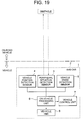
- FIG. 19 is a general block diagram showing the general conventional method of preventing collision with an obstacle.
- the obstacle collision prevention system 1 there are provided in the AHS car 2, which is a vehicle, a peripheral situation detection sensor 3 as an on-vehicle sensor for detecting a peripheral situation on the road, a vehicle position detection sensor 4 for detecting the car itself, a vehicle state detection sensor 5 for detecting a running speed of the vehicle itself, and an on-vehicle processing unit 6 for processing information from the sensors 3, 4, 5.
- Designated at the reference numeral 7 is a vehicle controller, and a running speed of the vehicle (steering angle) is automatically controlled (for speed reduction) by this vehicle controller 7. Then when any obstacle is detected by the peripheral situation detection sensor 3, an alarm is given to a driver from a vehicle HMI (Human Machine Interface) 8 which is an alarm unit based on information from the on-vehicle processing unit 6 to which the vehicle position detection sensor 4 and vehicle state detection sensor 5 are integrated. Upon reception of this alarm, the driver previously recognize a position of the obstacle and can evade the obstacle not to collide with it.
- a vehicle HMI Human Machine Interface
- a collision prevention system In a zone where a wide field of vision is not provided, namely in the so-called restricted field-of-vision zone such as a curved road not offering a wide field of vision as shown in Fig. 20, a driver can not visually recognize an obstacle from a distant position, a collision prevention system has been proposed in which information concerning obstacles are provided from obstacle detection devices provided on a road to the driver.
- the invention of Claim 1 comprises road facilities in turn comprising an obstacle detection facility for detecting information concerning an obstacle on a road, an on-road processing facility for processing information concerning obstacles detected by the obstacle detection facility with an on-road database in which road line form information is stored, road-to-vehicle communications facility for communicating information processed by this on-road processing facility to the road-to-vehicle communication facility loaded on the vehicle, and a plurality of fixed point information detection support facilities provided in a prespecified service area; a vehicle comprising, as on-vehicle devices, a fixed point information detection sensor for recognizing entry of the vehicle into the service area by detecting any of the detection support facilities, a road-to-vehicle communication unit for executing communication and delivery of information to and from the road-to-vehicle communications facility, a distance computing function for computing a distance between the running car and an obstacle, an on-vehicle processing unit having a collision determination function for determining possibility of collision based on the computed distance and is
- the preferred embodiment of invention defined in Claim 2 further comprises, in addition to the on-vehicle devices in the invention of Claim 1, a peripheral situation detection sensor for detecting an obstacle on a road, and is characterized in that the information detected by this peripheral situation detection sensor and that detected by the obstacle detection sensor and that detected by the obstacle detection facility are integrated with each other.
- the invention of Claim 3 comprises, in addition to the on-road facilities according to the invention of Claim 1 or Claim 2, a road surface situation detection facility for detecting a road surface situation such as humidity, fallen snow, and freezing on the road surface, and is characterized in that the road surface information is delivered by the road-to-vehicle communications facility to the vehicle, and assuming that the deceleration distance L 1 can be computed from the vehicle's deceleration degree a, a reaction time of the driver t 0 , the rising time t 1 , and a running speed of the vehicle v, the deceleration degree a can be estimated from the road surface information.
- An object of the present invention is to provide an obstacle collision prevention system which can quickly and accurately take necessary measures for prevention of collision when an AHS car is running in the "restricted field-of-vision zone", even if a vehicle running ahead suddenly decelerates.
- Fig. 1 is a block diagram illustrating general configuration of an obstacle collision prevention system according to one embodiment of the present invention.
- I/O data in the figure shows only information data essentially required in this invention. The present invention is described in detail below with reference to the general block diagram in Fig. 1.
- a feature of the present invention consists in the point that a position of an obstacle is detected by integrating obstacle information from a sensor provided on a vehicle and that from an obstacle detection facility provided in the on-road infrastructure (on-road facilities) for detecting obstacles.
- a peripheral situation detection sensor 3 as an on-vehicle sensor for detecting obstacles near the vehicle
- a vehicle position detection sensor 4 for detecting a position of the AHS car itself
- a vehicle state detection sensor 5 for detecting a running speed of the AHS car
- an on-vehicle processing unit 6 for processing information from the sensors 3, 4, and 5.
- the reference numeral 7 indicates a vehicle control unit, and a running speed (steering angle) of the AHS car is controlled by this vehicle control unit 7.
- the reference numeral 8 indicates a vehicle HMI as an alarm unit.
- the on-vehicle processing unit 6 is a unit which collects various types of information for the AHS car and computes/determines the possibility of collision based on the information, and computes a distance between the AHS car and an obstacle and a timing for starting braking, and the vehicle control unit 7 outputs an "instruction value" to the vehicle HMI 8.
- This "instruction value” is a timing value for speed reduction control as well as for generation of an alarm signal.
- the reference 9 indicates a road-to-vehicle communication unit for receiving information concerning a road surface detected by the on-road facilities as well as information concerning the obstacle. As described later, the information concerning an obstacle received by the road-to-vehicle communication unit 9 is directly delivered to the on-vehicle processing unit 6.
- the peripheral situation detection sensor 3 When an obstacle is detected by the peripheral situation detection sensor 3, information or an alarm is given to a driver of the AHS car from the vehicle HMI 8 which is an alarm unit based on information from the on-vehicle processing unit 6 based on the information from the vehicle position detection sensor 4 as well as from the vehicle state detection sensor 5.
- the on-road facilities include an obstacle detection facility 10 for detecting an obstacle on a road and a road surface situation detection facility 11 for detecting information on a surface of the road each as infrastructure.
- the obstacle detection facility 10 is a facility for basically detecting positions of obstacles (four or more-wheel cars at a stop and those running at a low speed) impeding smooth running of the AHS car, and this facility is installed in the "restricted field-of-vision zone" such as a curve not providing a wide field of vision in this example.
- the road surface situation detection facility 11 is a facility for detecting a situation of a road on which the AHS car is running, and more specifically this facility detects sections of the road surface where substantial changes such as “dry”, “humid”, and “frozen” are observed.
- the reference numeral 12 indicates an on-road processing facility which functions as a running support information preparation facility and executes such processing as preparation of output data or computing, and information concerning the road surface and information concerning an obstacle are delivered from the obstacle detection facility 10 and road surface situation detection facility 11 to this on-road processing facility 13.
- the reference numeral 14 indicates an on-road database, and road line form information is stored in this on-road database 14, and data delivery is executed, when required, between this on-road database 14 and the on-road processing facility 13.
- information delivery from the on-road database 14 is executed only in the "restricted field-of-vision zone" such as a curved road or a steep up or down slope.
- the road line form information can also be stored in a navigation system or the like in the AHS car 2, so that the road line form information from the AHS car 2 can also be used concurrently.
- Information concerning the road surface or obstacles detected by each of the facilities 10 and 11 is processed by the on-road processing facility 13 and is delivered via the road-to-vehicle communications facility 15 to the road-to-vehicle communications unit 9 in the AHS car 2.
- the fixed point information detection support facility 12 capable of recognizing information concerning lanes on a road as on-road infrastructure, and information concerning the lane situation detected by this fixed point information detection support facility 12 is delivered to a fixed point information detection sensor 17 provided on the vehicle. A situation of a road surface and obstacles on a road are detected based on the delivered information as well as on the detection information from the road-to-vehicle communication facility 15 and the peripheral situation detection sensor 3.
- the information concerning a road surface detected by each of the facilities 10, 11, 12 and information concerning obstacles are delivered via the road-to-vehicle communications facility 15 to the road-to-vehicle communication unit 9 on the vehicle, and as described above, an obstacle is detected by integrating the information from these peripheral situation detection sensors 3 and information concerning obstacles delivered to the road-to-vehicle communication unit 9.
- an alarm is issued from the alarm unit to the driver. Upon this alarm, the driver can evade the obstacle to prevent collision against it.
- Fig. 2 to Fig. 4 Configuration of and functions in the embodiment of the present invention are described in detail below with reference to Fig. 2 to Fig. 4.
- the following description assumes that an obstacle in a straight section of a vehicle-dedicated road is detected mainly by the peripheral situation detection sensor 3 (Refer to Fig. 1), and also that vehicles running in a zone where other services are provided can receive information concerning a road surface or the like.
- the "service area” as used in the following description indicates a specified road area (section) in which the "obstacle collision prevention method" can be effected.
- Fig. 2 shows a curved road (one side of a vehicle-dedicated road), one of sections to which the present invention is applied.
- a plurality of fixed point information detection facilities 12, 12 are provided at a substantially even interval (for instance, 2 m) , in the service area on the road, and of these, a fixed point information detection support facility 12a at the point P 1 functions as a service-in, while a fixed point information detection support facility 12b at the point P 5 functions as a service-out.
- lane markers or the like can be employed for the fixed point information detection support facilities.
- the fixed point information detection support facilities 12 at the points P 1 to P 4 function for identifying running vehicles.
- the reference 10 indicates the obstacle detection facility described in relation to Fig.
- this obstacle detection facility 10 is provided near the curved section close to the restricted field-of-vision zone as shown in the figure. As described above, as recognition of an obstacle (a vehicle at a stop) by the AHS car 2 is hard, the obstacle detection facility 10 is provided.
- a service is provided by the fixed point information detection facility 12a at the point P 1 , and the obstacle collision prevention function (service) is started (S1).
- S2 the obstacle collision prevention function
- S3 a distance from the point P 1 as a base point (service-in) is periodically calculated (S3).
- the AHS car 2 recognizes with the fixed point information detection support facilities 12 where the AHS car 2 itself is running (S4).
- positional information concerning a lane in which the obstacle is present and a distance from the base point P 1 to the obstacle is provided as obstacle information to the AHS car 2.
- This obstacle information is transmitted at a cycle together with the road surface situation information and road line form information via the road-to-vehicle communications facility 15 to the AHS car 2.
- a distance from the AHS car 2 to the obstacle is computed based on the obstacle information as well as on the distance between the AHS car 2 to the base point P 1 (S5).
- the AHS car 2 provides the information concerning the obstacle to the driver at the point P 2 as a point for starting provision of information (S6), and also determines the possibility of collision with the obstacle based on information concerning a lane in which the obstacle is present, a position of the obstacle in the lane, information on the distance between the AHS car 2 and the obstacle as well as on the road surface situation, and information on the road line form (S7).
- an alarm is given, for instance, with a buzzer to a driver of the AHS car 2 at the point P 2 as a point for starting an alarm (S8).
- a running speed of the AHS car 2 is automatically reduced at the point P 4 as a point for starting speed reduction to stop the AHS car 2 (S9).
- the lane tracking control or the deviation from lane prevention/alarm control unit can be used concurrently for the driver.
- the functions for reducing a running speed of and stopping the AHS car 2 is terminated at a time point when the AHS car 2 completely stops (S10). Then, at the time point when the AHS car 2 has passed by the point P 5 as a point for service-out for the fixed point information detection support facility 12b, provision of a series of services by the system is terminated (S11).
- a range of the "restricted field-of-vision zone" in a service area naturally varies from place to place on the road, arrangement of the fixed point information support facilities for service-in and service-out and obstacle detection facilities should be examined each time according to a form of the road to which the present invention is applied.
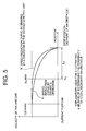
- Fig. 5 is an explanatory view showing general contents of the determination method employed in (an example of) the obstacle collision prevention system according to the present invention.
- the curve A is a "speed-position curve" for a normal case where a driver reduces a running speed of a car in front of (immediately before) an obstacle and stops the car
- the curve B is a "speed-position curve” for an emergent case where a driver brakes in an emergency or where a running speed of an AHS car is reduced by the vehicle control unit 7 (Refer to Fig. 1) on the AHS car and then the AHS car is stopped.
- the "speed-position" curves shown by the curves A and B can be prepared by the on-vehicle processing unit 6 (Refer to Fig.
- the on-vehicle processing unit determines the possibility for the AHS car to collide with the obstacle by constantly monitoring the vehicle's position, the running speed, and line form of the road, and determines in this example that the AHS car may collide against the obstacle at the time point when the AHS car has reached the "point P A " in the figure, and an alarm is given to the driver at the "point P A ".
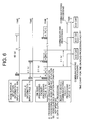
- Fig. 6 shows an example of a time chart which is applied to the present invention as described above.
- this time chart mainly shows the on-road facility for the road section (curved road) as shown in Fig. 2.
- the figure A shows the processing for obstacle information
- figure B shows the processing for information concerning a road surface situation
- the figure C shows the data output processing.
- (B) in Fig. 6 assumes that updating of road surface data is not performed.
- an input cycle of information concerning the road surface situation starts once for every 60 seconds
- an input cycle for the obstacle information, a processing cycle of the on-road processing facility 13, and a processing cycle of the road-to-vehicle communications facility 15 start once for every 0.1 second.
- the processing for information concerning the road surface situation is executed simultaneously when the information concerning the road surface information is inputted, and when the data output processing is executed, the processing for communications to each AHS car is executed via the on-road communication facility.
- Input information in the information is the obstacle information and that concerning a road surface situation, and of these, the obstacle information is obtained once for every 0.1 second from the obstacle detection facility 10, while the information concerning a road surface situation is obtained once for every 60 seconds from the road surface situation detection facility 11 and is stored in the on-road database 14.
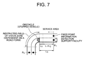
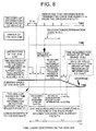
- Fig. 7 and Fig. 8 are a time chart and a view for explanation of functions for computing a management area by the on-road facilities according to the present invention, and these figures mainly show an AHS car and the driver's operation.
- the management area by the on-road facility according to the present invention is a range of the "restricted field-of-vision zone" plus a range from a fixed point information detection support facility to an entrance of the "restricted filed-of-vision zone".
- the range of the restricted field-of-vision zone depends on a form of a road, so that in this example a distance L 3 from the fixed point information detection support facility (at the point P 1 ) to an entrance of the "restricted field-of-vision zone", and more specifically this "distance L 3 " can be computed through the equation 3 below.
- L 3 L 2 + L 1 + L 0
- the "distance L 0 " indicates a distance over which the AHS car runs for a period of time t 2 from a time point when it passes by the fixed point information detection support facility, and specifically this "distance L 3 " can be computed through the following equation 2:
- L 3 V ⁇ t 2
- the distance L 0 indicates an allowance distance required when the AHS car stops with a certain degree of allowance in front of an obstacle, and this "allowance distance L 0 " is computed through the equation 4 below:
- L 0 Average car head time ⁇ 0.1 ⁇ running speed
- This value of L 3 is the same as the value of the detection range detected by the peripheral situation detection sensor 3. This also suggests that also the detection range when an obstacle is detected by a peripheral situation detection sensor on the AHS car is the above value (about 300 m).
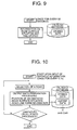
- Fig. 9 and Fig. 10 indicate a flow of the processing executed by the on-road processing facility 13 for the object shown in Fig. 2.
- Fig. 9 is a flow of processing the information concerning a road surface situation detected by the road surface situation detection facility 11.
- the processing by the on-road situation processing facility 11 is started "once for every 60 seconds" simultaneously when the processing flow above is started, and the information concerning the road surface situation detected by this road surface situation detection facility 11 and data on the detection time are stored as "stored data" in the on-road database 14 respectively.
- Fig. 10 shows a flow of processing for preparation of output data to be set to an AHS car.
- the "processing flow” is started upon input of obstacle information once for every 0.1 second, and at first "acquisition of obstacle information” is performed in response to "selection of a road”, and then the "preparation of output data” is performed based on the "stored data" stored in the on-road database facility 14 by transacting information concerning a position of the obstacle, a road surface situation, a road line form, and others to and from the on-road processing facility 13.
- the prepared output data is transmitted via the road-to-vehicle communications facility 15 to the AHS car, and this processing flow is terminated at the time point "when information on obstacles on all roads has been processed".
- Fig. 11 shows an example of "input/output data" for a up-and-down road having two lanes (way Y 1 , way Y 2 ) in one side. More specifically Fig. 11 shows an example in which a radius of the curved road is "400 mm" and lengths of the straight sections in both sides of this curved section is "300 mm” respectively, and a list of "input data" for the on-road processing facility 13 in Fig. 11 is shown in Table 1 below.
- a large item for "data” is positions of obstacles on the first and second lanes on the way Y 1 and way Y 2 respectively, and as for the "input source" of obstacle information and information on a road surface situation, data detected by the obstacle detection facility 10 and road surface detection facility 11 are inputted at a specified cycle.
- Data Data quantity Input source Input cycle Large item Detail Obstacle information Position of an obstacle in the first lane of Way Y 1 1 AHS car on the way Y 1 0.1 s Position of an obstacle in the second lane of Way Y 1 1 AHS car on the way Y 1 0.1 s Position of an obstacle in the third lane of Way Y 1 1 AHS car on the way Y 1 0.1 s Position of an obstacle in the first lane of Way Y 2 1 AHS car on the way Y 2 0.1 s Position of an obstacle in the second lane of Way Y 2 1 AHS car on the way Y 2 0.1 s Position of an obstacle in the third lane of Way Y 2 1 AHS car on the way Y 2 0.1 s Road line form (Note 1) Position at which a slope of the way Y 1 changes 3 AHS car on the way Y 1 0.1 s Average slope
- the "road line form information” is added as a large item for output data.
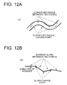
- Detail of the “road line form” is shown in Fig. 12 (A) and Fig. 12 (B).
- the "road line form” data in a service area includes a point (position) where a slope of a road changes, an average slope between two change points and a point (position) where the curvature radius changes, and a curvature radius between two change points, and as the service area as shown in Fig. 11 is actually short in its distance (several hundred meters), so that the curvature and slope change at maximum three points.
- Fig. 17 is a block diagram showing the on-road processing facility and a management area thereby.
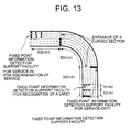
- Fig. 13 shows an example of installation of the fixed point information detection support facility. As shown in Fig. 13, when the fixed point information detection support facilities are provided at the interval of 10 m, 60 fix point information detection support facilities are required for one lane (240 pieces in all). Further two fixed point information detection support facilities are required for service in and out for each lane in each service area (12 pieces in all).
- Fig. 14 shows one example of the road surface situation detection facility. Under the conditions of "curved vehicle-dedicated road without any signal", the road surface situation detection facility is provided at a point along a curve of the road not providing a wide field of vision.
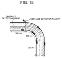
- Fig. 15 shows an example of installation of the obstacle detection facilities.
- a "detection range" by one obstacle detection facility is 200 m and detection of obstacles in three lanes are possible
- three obstacle detection facilities are required for one way as shown in Fig. 15 (6 units of sensor heads in all for two (up and down) ways).
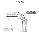
- Fig.16 shows an example of installation of the road-to-vehicle communications facility. As shown in Fig. 16, the entire service area is a "communication range" for this road-to-vehicle facility.
- Fig. 17 shows an example of the on-road facility as well as of a management range thereby.
- the on-road processing facility as a base
- the road surface situation detection facility, obstacle detection facilities, on-road database, and road-to-vehicle communications facility are installed at respective specified positions, thus information management in a wide area being enabled.
- Fig. 18 is an explanatory view for illustrating discrete communications between a road and a vehicle in this invention. It is assumed in the following description that obstacles 25 to 27 are present on two lanes of the road, and two AHS cars 2a, 2b are running on one of the two lanes (in the lower one in Fig. 18) as shown in Fig. 18. Namely in this embodiment, as obstacle information for each of the AHS cars, information concerning the two obstacles 25 and 26 is transmitted to the AHS car 2a, and information on the obstacle 27 which the AHS car 2a has passed by is not transmitted. In contrast, information on the obstacles 26 and 27 is transmitted to the AHS car 2b, and information on the obstacle 25 at a forward position from the obstacle 27 is not transmitted.
- the possibility that the AHS car 2a running ahead of the AHS car 2b reduces the running speed and then stops to evade collision with the obstacle 26 is guessed by the on-road facilities including the on-road processing facility 13, and an alarm or an instruction for evading can properly be delivered to the AHS car 2b, thus enabling the AHS car 2b to evade a rear-end collision with the AHS car 2a.
- the AHS car 2a actually reduces the running speed and then stops more accurate information can be provided by transmitting the information from the AHS car 2a via the on-road facility to the AHS car 2b.
- the invention of Claim 1 provides an obstacle collision prevention system comprising an on-road facility in turn comprising an obstacle detection facility for detecting information concerning obstacles on a road, an on-road processing facility for processing information on obstacles detected by said obstacle detection facility using an on-road database with road line form stored therein, a road-to-vehicle communications facility for communicating and delivering the information processed by said on-road processing facility to a road-to-vehicle communications unit on the vehicle, and a plurality of fixed point information detection support facilities provided in a specified service zone; and a vehicle comprising, as on-vehicle devices, a fixed point information detection sensor for recognizing that the vehicle has entered a service zone by detecting the fixed point information detection support facility, a road-to-vehicle communications unit for transacting information with that on the road, an on-vehicle processing unit having a distance computing function for computing while running a distance between the vehicle and an obstacle and a collision determination function for determining the possibility of collision based on the computed distance and issuing an
- the obstacle collision prevention system Because of the features of the obstacle collision prevention system according to the present invention, there is provided the advantage that necessary and efficient information can accurately be computed and selected at appropriate timing, and controls and instructions for preventing a read-end collision with another vehicle or for evading a collision with an obstacle can accurately be delivered.
- the invention of Claim 2 provides the obstacle collision prevention system according to Claim 1 further comprising, as a on-vehicle device, a peripheral situation detection sensor for detecting a peripheral situation around an obstacle on a road, wherein information detected by this peripheral situation detection sensor is integrated with information detected by the obstacle detection facility. Because of the features of the obstacle collision prevention system according to the present invention, there is provided the advantage that necessary and efficient information can be selected and a collision with an obstacle can quickly and accurately be evaded even when an AHS car is running in the "restricted field-of-vision zone" or when a vehicle running ahead suddenly reduces the running speed. Further, as a traffic accident of a running AHS car can be prevented, safety of car drivers can be insured, and the possibility of traffic jam can be reduced.
- the invention of Claim 3 provides the obstacle collision prevention system according to Claim 1 or Claim 2 further comprising, as an on-road facility, a road surface situation detection facility for detecting a road surface situation such as humidity, fallen snow on and freezing of a road. Because of the features of the obstacle collision prevention system according to the present invention, there is provided the advantage that an alarm can be issued to a driver and information for proper timing for braking to stop the vehicle can accurately be obtained by automatically delivering the information on detected road surface situation and computing a distance required for stopping the vehicle.
Landscapes
- Physics & Mathematics (AREA)
- General Physics & Mathematics (AREA)
- Traffic Control Systems (AREA)
- Control Of Driving Devices And Active Controlling Of Vehicle (AREA)
Applications Claiming Priority (2)
| Application Number | Priority Date | Filing Date | Title |
|---|---|---|---|
| JP30491599A JP3174831B2 (ja) | 1999-10-27 | 1999-10-27 | 障害物衝突防止システム |
| JP30491599 | 1999-10-27 |
Publications (2)
| Publication Number | Publication Date |
|---|---|
| EP1096460A2 true EP1096460A2 (fr) | 2001-05-02 |
| EP1096460A3 EP1096460A3 (fr) | 2001-11-28 |
Family
ID=17938846
Family Applications (1)
| Application Number | Title | Priority Date | Filing Date |
|---|---|---|---|
| EP00309516A Withdrawn EP1096460A3 (fr) | 1999-10-27 | 2000-10-27 | Système pour empêcher des collisions entre un véhicule et un obstacle |
Country Status (2)
| Country | Link |
|---|---|
| EP (1) | EP1096460A3 (fr) |
| JP (1) | JP3174831B2 (fr) |
Cited By (10)
| Publication number | Priority date | Publication date | Assignee | Title |
|---|---|---|---|---|
| US6774815B2 (en) * | 2001-03-08 | 2004-08-10 | National Institute For Land And Infrastructure Management, Ministry Of Land, Infrastructure And Transportation | On-road facility fault information communication apparatus |
| EP1494194A2 (fr) | 2003-07-04 | 2005-01-05 | Fuji Jukogyo Kabushiki Kaisha | Appareil et procédé de freinage pour véhicule |
| US7278505B2 (en) * | 2005-03-15 | 2007-10-09 | Omron Corporation | Control device for starting motion of mobile body |
| EP2071541A1 (fr) * | 2007-12-12 | 2009-06-17 | Robert Bosch GmbH | Procédé destiné à la surveillance d'une situation de trafic |
| US9180885B2 (en) | 2011-03-18 | 2015-11-10 | Toyota Jidosha Kabushiki Kaisha | Drive assist apparatus, and information processing apparatus for vehicles |
| CN114757385A (zh) * | 2021-01-08 | 2022-07-15 | 丰田自动车株式会社 | 配送系统 |
| US20220324438A1 (en) * | 2019-12-24 | 2022-10-13 | Huawei Technologies Co., Ltd. | Method and Apparatus for Controlling Automated Vehicle |
| CN115556738A (zh) * | 2022-10-17 | 2023-01-03 | 质子汽车科技有限公司 | 基于区域控制架构的线控底盘及新能源电动商用车辆 |
| CN117922559A (zh) * | 2024-03-07 | 2024-04-26 | 南通职业大学 | 一种汽车智能道路预警系统 |
| US12162349B2 (en) | 2021-02-01 | 2024-12-10 | Caterpillar Paving Products Inc. | Controlling machine operation including limiting machine speed |
Families Citing this family (7)
| Publication number | Priority date | Publication date | Assignee | Title |
|---|---|---|---|---|
| JP3924615B2 (ja) * | 2003-03-14 | 2007-06-06 | 国土交通省国土技術政策総合研究所長 | 電波方向探知装置を利用した走行支援システム |
| JP2005127909A (ja) | 2003-10-24 | 2005-05-19 | Fujitsu Ten Ltd | レーダの走査方法 |
| JP4030572B2 (ja) * | 2006-01-24 | 2008-01-09 | 横浜ゴム株式会社 | 車両制動距離予測装置および車両制動距離予測方法 |
| DE102007003255A1 (de) | 2006-01-24 | 2007-09-06 | The Yokohama Rubber Co., Ltd., Hiratsuka | Vorrichtung und Verfahren zum Vorhersagen eines Bremswegs eines Fahrzeugs |
| JP5300357B2 (ja) * | 2008-07-22 | 2013-09-25 | 日立オートモティブシステムズ株式会社 | 衝突防止支援装置 |
| JP2019503165A (ja) * | 2015-11-17 | 2019-01-31 | ボルボトラックコーポレーション | 車両に近づく道路状況を検知する方法 |
| WO2024116363A1 (fr) | 2022-12-01 | 2024-06-06 | 株式会社Subaru | Système d'aide à la conduite, véhicule, support d'enregistrement, programme informatique d'enregistrement et procédé d'aide à la conduite |
Family Cites Families (3)
| Publication number | Priority date | Publication date | Assignee | Title |
|---|---|---|---|---|
| JP3133770B2 (ja) * | 1991-01-18 | 2001-02-13 | マツダ株式会社 | 自動車の走行システム |
| JP3191621B2 (ja) * | 1995-03-14 | 2001-07-23 | トヨタ自動車株式会社 | 車両走行誘導システム |
| US6026347A (en) * | 1997-05-30 | 2000-02-15 | Raytheon Company | Obstacle avoidance processing method for vehicles using an automated highway system |
-
1999
- 1999-10-27 JP JP30491599A patent/JP3174831B2/ja not_active Expired - Lifetime
-
2000
- 2000-10-27 EP EP00309516A patent/EP1096460A3/fr not_active Withdrawn
Cited By (12)
| Publication number | Priority date | Publication date | Assignee | Title |
|---|---|---|---|---|
| US6774815B2 (en) * | 2001-03-08 | 2004-08-10 | National Institute For Land And Infrastructure Management, Ministry Of Land, Infrastructure And Transportation | On-road facility fault information communication apparatus |
| EP1494194A2 (fr) | 2003-07-04 | 2005-01-05 | Fuji Jukogyo Kabushiki Kaisha | Appareil et procédé de freinage pour véhicule |
| EP1494194A3 (fr) * | 2003-07-04 | 2007-12-19 | Fuji Jukogyo Kabushiki Kaisha | Appareil et procédé de freinage pour véhicule |
| US7278505B2 (en) * | 2005-03-15 | 2007-10-09 | Omron Corporation | Control device for starting motion of mobile body |
| EP2071541A1 (fr) * | 2007-12-12 | 2009-06-17 | Robert Bosch GmbH | Procédé destiné à la surveillance d'une situation de trafic |
| US9180885B2 (en) | 2011-03-18 | 2015-11-10 | Toyota Jidosha Kabushiki Kaisha | Drive assist apparatus, and information processing apparatus for vehicles |
| US20220324438A1 (en) * | 2019-12-24 | 2022-10-13 | Huawei Technologies Co., Ltd. | Method and Apparatus for Controlling Automated Vehicle |
| US12319277B2 (en) * | 2019-12-24 | 2025-06-03 | Shenzhen Yinwang Intelligent Technologies Co., Ltd. | Method and apparatus for controlling automated vehicle |
| CN114757385A (zh) * | 2021-01-08 | 2022-07-15 | 丰田自动车株式会社 | 配送系统 |
| US12162349B2 (en) | 2021-02-01 | 2024-12-10 | Caterpillar Paving Products Inc. | Controlling machine operation including limiting machine speed |
| CN115556738A (zh) * | 2022-10-17 | 2023-01-03 | 质子汽车科技有限公司 | 基于区域控制架构的线控底盘及新能源电动商用车辆 |
| CN117922559A (zh) * | 2024-03-07 | 2024-04-26 | 南通职业大学 | 一种汽车智能道路预警系统 |
Also Published As
| Publication number | Publication date |
|---|---|
| JP2001126196A (ja) | 2001-05-11 |
| JP3174831B2 (ja) | 2001-06-11 |
| EP1096460A3 (fr) | 2001-11-28 |
Similar Documents
| Publication | Publication Date | Title |
|---|---|---|
| EP1096458B1 (fr) | Système pour éviter une collision sur un carrefour | |
| EP1095832B1 (fr) | Système pour la prévention des collisons entre des véhicules et des piétons | |
| EP1104881B1 (fr) | Système de commande de véhicule | |
| EP1096460A2 (fr) | Système pour empêcher des collisions entre un véhicule et un obstacle | |
| US10460181B2 (en) | Processing of sensor data for a driver assistance system | |
| JP5453048B2 (ja) | 車両の運転支援制御装置 | |
| US8330592B2 (en) | Collision warning device for motor vehicles | |
| JP4715826B2 (ja) | 車両運転支援システム、運転支援装置、車両及び車両運転支援方法 | |
| US20100004839A1 (en) | Driving assisting apparatus and driving assisting method | |
| CN107170291B (zh) | 一种行车提示方法、提示系统、车载终端及汽车 | |
| JP7232100B2 (ja) | 車両の走行制御装置 | |
| JP5141783B2 (ja) | 運転支援装置、車両及び車両運転支援方法 | |
| JP2000339599A (ja) | 自動追従走行システム | |
| JP2002178864A (ja) | 電気自動車の制御装置 | |
| JP2009173093A (ja) | 車両運転支援システム、運転支援装置、車両及び車両運転支援方法 | |
| US20200339125A1 (en) | Method for operating a driving assistance system, and driving assistance system | |
| CN114023077B (zh) | 一种交通监控方法与装置 | |
| US6360171B1 (en) | Bumping prevention system | |
| EP1096459B1 (fr) | Système d'évitement de collision | |
| JPH10124799A (ja) | 車両用走行安全検知装置及び車両用走行制御装置 | |
| WO2008084408A2 (fr) | Appareil de surveillance périphérique | |
| US20060229812A1 (en) | Device radio-based danger warning | |
| JP2009176056A (ja) | 情報提供装置、情報提供システム、車両及び情報提供方法 | |
| US12384379B2 (en) | Information processing device, vehicle control unit, and road information distribution method | |
| JPH09128686A (ja) | 車両用表示装置 |
Legal Events
| Date | Code | Title | Description |
|---|---|---|---|
| PUAI | Public reference made under article 153(3) epc to a published international application that has entered the european phase |
Free format text: ORIGINAL CODE: 0009012 |
|
| 17P | Request for examination filed |
Effective date: 20001220 |
|
| AK | Designated contracting states |
Kind code of ref document: A2 Designated state(s): DE FR GB IT Kind code of ref document: A2 Designated state(s): AT BE CH CY DE DK ES FI FR GB GR IE IT LI LU MC NL PT SE |
|
| AX | Request for extension of the european patent |
Free format text: AL;LT;LV;MK;RO;SI |
|
| PUAL | Search report despatched |
Free format text: ORIGINAL CODE: 0009013 |
|
| AK | Designated contracting states |
Kind code of ref document: A3 Designated state(s): AT BE CH CY DE DK ES FI FR GB GR IE IT LI LU MC NL PT SE |
|
| AX | Request for extension of the european patent |
Free format text: AL;LT;LV;MK;RO;SI |
|
| RIC1 | Information provided on ipc code assigned before grant |
Free format text: 7G 08G 1/16 A, 7B 60K 31/00 B |
|
| RIN1 | Information on inventor provided before grant (corrected) |
Inventor name: TAKIGUCHI, AKIHIKO Inventor name: MURAKAMI, HIDEAKI, C/O OMRON CORPORATION Inventor name: YAMADA, MASAYA, C/O SUMITOMO ELECTRIC IND.,LTD. Inventor name: TAKAHASHI, HIROSHI, C/O NISSAN MOTOR CO., LTD Inventor name: OOYA, HARUTADA Inventor name: NOGUCHI, NAOYA C/O ISHIKAWAJIMA-HARIMA HEAVY IND. Inventor name: MOTEKI, SATOSHI, C/O ISUZU MOTORS LTD. Inventor name: KUBOTA, KOJI, C/O NIPPON TELEGRAPH & TELEPHONE CO |
|
| 17Q | First examination report despatched |
Effective date: 20020527 |
|
| AKX | Designation fees paid |
Free format text: DE FR GB IT |
|
| STAA | Information on the status of an ep patent application or granted ep patent |
Free format text: STATUS: THE APPLICATION IS DEEMED TO BE WITHDRAWN |
|
| 18D | Application deemed to be withdrawn |
Effective date: 20021008 |