EP1096463A2 - Plakatwand - Google Patents
Plakatwand Download PDFInfo
- Publication number
- EP1096463A2 EP1096463A2 EP00114776A EP00114776A EP1096463A2 EP 1096463 A2 EP1096463 A2 EP 1096463A2 EP 00114776 A EP00114776 A EP 00114776A EP 00114776 A EP00114776 A EP 00114776A EP 1096463 A2 EP1096463 A2 EP 1096463A2
- Authority
- EP
- European Patent Office
- Prior art keywords
- column
- elements
- billboard according
- billboard
- use position
- Prior art date
- Legal status (The legal status is an assumption and is not a legal conclusion. Google has not performed a legal analysis and makes no representation as to the accuracy of the status listed.)
- Withdrawn
Links
Images



Classifications
-
- G—PHYSICS
- G09—EDUCATION; CRYPTOGRAPHY; DISPLAY; ADVERTISING; SEALS
- G09F—DISPLAYING; ADVERTISING; SIGNS; LABELS OR NAME-PLATES; SEALS
- G09F1/00—Cardboard or like show-cards of foldable or flexible material
- G09F1/04—Folded cards
- G09F1/06—Folded cards to be erected in three dimensions [3D]
-
- G—PHYSICS
- G09—EDUCATION; CRYPTOGRAPHY; DISPLAY; ADVERTISING; SEALS
- G09F—DISPLAYING; ADVERTISING; SIGNS; LABELS OR NAME-PLATES; SEALS
- G09F1/00—Cardboard or like show-cards of foldable or flexible material
- G09F1/04—Folded cards
- G09F1/06—Folded cards to be erected in three dimensions [3D]
- G09F1/065—Totem-like displays; Portable collapsible columnar displays
-
- G—PHYSICS
- G09—EDUCATION; CRYPTOGRAPHY; DISPLAY; ADVERTISING; SEALS
- G09F—DISPLAYING; ADVERTISING; SIGNS; LABELS OR NAME-PLATES; SEALS
- G09F15/00—Boards, hoardings, pillars, or like structures for notices, placards, posters, or the like
- G09F15/0068—Modular articulated structures, e.g. stands, and articulation means therefor
Definitions
- the present invention relates to a billboard made of cardboard material by a flat non-use position can be converted into an upright use position is and comprises a column element, the two lying flat on top of each other in the non-use position, wall areas connected to one another at their side edges and at least one, the wall areas in the use position at least in their middle Section comprises spreading apart from each other.
- Such a billboard or a display is known from DE 7802400 U1.
- This consists of a hollow body consisting of two essentially vertical walls that face each other parallel, at least approximately vertical edges connected together are.
- the hollow body has an expansion support that in the use position in a double convex shape, so that the hollow body in cross section a lens shape occupies.
- a wide variety of spreading agents are described in this publication. Folding down the display along a transverse folding line is also part of the package this state of the art.
- the hollow body is preferably made of one piece Cardboard blank made, glued on one side using an adhesive flap becomes. Under certain circumstances, covers can be provided.
- Such an element has Proven very well as a sales display and by different groups of several Such pillar elements can be used in a wide variety of forms. However, the handling, especially with relatively large displays, still allows wish left.
- This object is achieved in that in addition to the column element at least one poster element is arranged, and that in each case one side edge of the one Element with the side edge of the other element through a hinge connection for transferring the elements from a flat, unfolded position when not in use are connected to each other in an erect position of use. That means, that the poster area can be enlarged within a single unit can.
- the individual elements of the billboard are immovable to each other by means of the Hinge connection attached, so that a substantially closed poster surface can be generated. This relatively large billboard can be removed from a single one when not in use erect basic element folded flat.
- the pillar element the billboard ensures regardless of the angular position of the poster element to the pillar element for sufficient stability.
- any number of poster elements can be on the column element to be ordered. This can be done on the one hand to the left and to the right of the Pillar element arranged poster element happen and on the other hand can further poster elements on the poster elements in turn via hinge connections be arranged.
- At least one poster element as a column element is designed with a spreading device.
- Column elements can be provided. These are then also by means of hinge connections directly on the basic column element or on adjacent flat poster elements pivotally arranged. It is also important here that despite one such large billboard this again in a relatively small area and folded flat Is not transferable to use. So that also relatively rigid cardboard materials, which may have a considerable thickness, folded flat on each other , it is further preferred if the hinge connection between the elements are designed to be elastic. This then allows the flat to be folded up without further ado in the non-use position. In addition, such elastic tear Hinge connections are not as quick as simple folding lines in the Cardboard material itself.
- the hinge connection can advantageously be hooking devices in the region of the side edges the elements and then include hooked elastic bands or cords, the elastic bands or cords from one element to the adjacent Extend element.
- Elastic bands or cords are available in a variety of forms and made of different materials that are suitable for this purpose. For Simple ring rubbers of suitable strength can be used, which then come into the Hooking devices are hooked or hooked.
- the elastic bands or cords are sufficiently pre-tensioned to keep the side edges of the elements close together. Provided the hooking devices are designed to be sufficiently stable can be considerable Tensile load can be applied by means of the elastic bands or cords that are used for a correspondingly close arranged elements and still provide one have sufficient hinge effect.
- the glued adhesive tabs can preferably be provided with the hooking devices his.
- the actual viewing areas of the billboard remain from any facilities untouched, so that the full area is available for representations, whereas the hooking devices advantageously in an extremely stable area of the Column element are arranged.
- By sticking the adhesive tabs together a relatively stable anchoring option has been found.
- the hooking devices can also by one Be formed slot that extends through both interconnected adhesive tabs and in which the elastic band or the elastic cord is hooked.
- the double layer in this area ensures that the elastic band or the elastic Line does not dig further into the material and is securely hooked in place.
- the elastic band or the elastic cord is V-shaped from a hooking slot to the corresponding hooking slot of the adjacent element, the V-tip essentially the Hinge axis defined. Due to the V-shaped arrangement, the preload is extended and the elastic band or elastic cord can be chosen longer, what the most diverse advantages regarding the hinge effect of the applied Preload brings with it. Even the hooking process for the elastic The band or elastic cord is designed based on the available length this element is not very difficult. would only be the vertical distance from the hooking point are available to the hooking point while facing major problems available.
- the spreading devices can have a wide variety of cross-sectional shapes for the Column elements can be achieved. However, it is preferred if by the shape and the structure of the at least one spreading device in the column elements Position of use erected into a hollow body with a lenticular cross section are. Two wall sections of the same size, connected to each other at their side edges are only spread apart for this purpose, whereby they are then automatically take the arched shape.
- the design of the spreader can be very diverse Be in shape.
- One possibility is that the backing Wall area with a punch to form an inward foldable spreading flap is provided, which serves as an expansion element. From the level of this wall area the spreading flap is only bent inwards, so that the Erection takes place to a hollow body. No further manipulations are necessary Due to the preload, the spreading flap is held in position.
- the elements have a folding line running transversely to their vertical extent, are foldable around the wall areas of the non-use position.
- Such folding lines stiffen in the use position due to the use of the spreading devices automatically off, so that an unwanted folding in the use position cannot take place. Only when the wall areas of the column elements or the Poster elements placed flat on top of each other can be folded over along the folding line respectively. The size of the transport area in the non-use position is halved in each case by using a folding line. Multiple folding lines can also be used Find.
- the column elements can consist of at least one upper one, above the Folding line arranged column part and at least one lower, below the Folding line arranged column part can be built up to form the folding line a hinge connection are connected, which is locked in the use position.
- These column parts made from cardboard blanks are preferred with one another glued.
- the arrangement of the adhesive tabs can be cleverly chosen that a safe configuration of a folding line takes place. For example, on the On the visible side there is a continuous, almost seamless connection, whereas on the rear of the connection is relatively open, so that e.g. folding or Unfolding four layers of cardboard is possible.
- the large billboard 1 shown in Fig. 1 comprises three vertical column elements 2, the vertical side edges 3, 4 along a hinge line 5 with each other are connected. This means that the three column elements 2 side by side are arranged, with only the central column element 2 connecting to the adjacent one Column element 2 on each side edge 3 and 4 comprises.
- the pillar elements 2 have a substantially centrally arranged folding line 6, which, however, in the 1 is locked in use position shown. so that no folding takes place can.
- Each column element 2 is through the folding line 6 into a lower column part 7 and an upper column part 8 divided.
- the billboard 1 has a substantially rectangular shape in the front view.
- the individual column elements 2 and column parts 7 and 8 are also in the front view rectangular.
- 1 is the front side 9 or actual poster side of the billboard 1 shown, which are appropriately printed or glued or used in any other way can be.
- each pillar part 7, 8 of the pillar element 2 is made of is produced two cardboard blanks that are substantially rectangular.
- the the first cardboard blank forms the front wall area 10 and the second cardboard blank the rear wall area 11.
- On their side edges 3 and 4 are the Wall areas 10 and 11 each provided with an adhesive flap 12 and 13 which run along a fold line 14, 15 is folded inwards into the interior of the column element 2.
- the Adhesive tabs 12 and 13 run approximately over the entire height of the column parts 7, 8 and have a substantially rectangular shape in the front view.
- the outside the adhesive flaps 12 and 13 lie along the fold line 14 due to the folding, 15 parallel to each other and are glued together by interposing adhesive, so that a relatively stable web 16 into the interior 17 of the column element 2 protrudes.
- the two webs 16 of a column element 2 remain essentially in its middle level.
- the wall areas 10 and 11 are convex bent outward so that the entire column member is substantially lenticular Cross section.
- This arrangement of the wall areas 10 and 11 in the The position of use is determined by a spreading element 18 which can be folded into the interior 17 causes. If the expansion element 18 is inactive in the non-use position, the Wall regions 10 and 11 are arranged essentially flat parallel to one another.
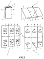
- the column elements 2 are both along the hinge lines 5 and along the Folding lines 6 folded, so that the non-use position shown in Fig. 2 top left is obtained.
- the area that this element occupies is essentially the same the area of a single column part 7 or 8. This means that essentially all column parts 7 and 8 lie parallel on top of each other, making a twelve-fold Wall area layer thickness is achieved.
- the wall areas 11 on the back of the billboard 2 are punched or punched out provided in the form of a folding tab, which as an expansion element 18 along an arcuate Folding line 19 can be folded into the interior 17.
- a connection of the expansion element 18 to the wall area 11 is maintained, while all other side edges of the expansion element 18 completely by one Punching process are separated from the wall area 11.
- the top edge 20 the expansion element 18 is also arcuate, so that there is an optimal Clinging to the front wall area 10 results in the use position.
- a finger hole 21 can be provided on the upper edge 20 for better handling his.
- Each column part 7 and 8 has such an expansion element 18 on its rear side on.
- expansion elements 18 are folded inwards along the fold line 19, as a result of which the column elements 2 assume the cross-sectional shape shown in FIG. 3 and can stand independently, as shown in Fig. 2 bottom right. On the At the back there are openings through the folding of the expansion elements 18 arise.
- the hinge connection between the individual column elements 2 described is used in one embodiment for the hinge connection between the individual column elements 2 described.
- the upper hinge connection is an example shown. This is analogous to all connections along the whole Transfer height of the column element 2.
- the web 16 does not extend to the total height of the associated column part 7, but instead ends at a distance from the top edge of the billboard. This leaves a slot 22 between the two adjacent column elements 2.
- the upper edge 23 of the web 16 is a hooking slot 25 incorporated.
- This hooking slot 25 begins horizontally and describes up a quarter arc and ends in a substantially circular Hole 26, which extends completely horizontally through the web 16.
- a similar hooking slot 25 which is essentially mirror-symmetrical to the hinge line 5 to that of the adjacent column element 2 is arranged.
- one end 27, 28 of a ring rubber is hooked in each case.
- the folding line 6 is preferably designed such that the front of the billboard 1 is continuous and has a simple, ordinary fold line, whereas on the back constructions with cross slots and wider connecting straps can be provided, the corresponding folding without further notice enable.
- 5a shows the arrangement of the three column elements 2 to form a uniform column in FIG a kind of triangular shape with convex side walls.
- 5b shows a semicircular Arrangement of the column elements 2.
- a zigzag arrangement or serpentine arrangement is shown in Fig. 5c. From this it can be seen that the hinge connections are extremely flexible and bend the column elements in any direction 2 can be done.
- 5d shows the straight arrangement of the column element 2 in a plane similar to that shown in FIG. 1.
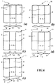
- FIGS. 6a to 6e Various variants for a billboard 1 are now based on FIGS. 6a to 6e shown.
- 6a shows once again the already known arrangement with three identical column elements, which assume a lens shape in cross-section in the use position.
- the Poster element 31 has the same height and width as the column elements 2 and therefore also stands on the floor.
- the folding line 6 is also at the same height extended so that the poster element 31 can also be folded down.
- the poster element from a simple cardboard blank or from a double layer Cardboard blank that is not provided with expansion elements and remains flat, as can be seen in the top view. Even in a straight line such a billboard has sufficient stability due to use from the column elements 2.
- FIG. 6c shows a further variant in which a flat poster element 31 is used is arranged between two outer column elements 2. Also corresponds the height and width of the poster element 31 essentially the height and Width of the column elements 2 and also the folding line 6 is continuous.
- FIGS. 6a to 6e again shows a further variant in which the column element 2 is on the outside and adjoin it two flat poster elements 31.
- the poster elements 31 are also column elements 2 can, the expansion element 18 has not been folded inwards, which makes them maintain flat shape.
- All of the variants shown in FIGS. 6a to 6e can also be seen in FIG in Fig. 1 billboard 1, by appropriately folding and unfolding the Generate spreading elements 18.
- FIGS. 5a to 5d and in particular FIGS. 6a to 6e that starting from from a billboard 1, as shown in Fig. 1, a large variety of different Set-up or presentation options result in this form up to now were not present.
- the partial non-spreading of column elements 2 is not yet known, since these do not stand by themselves, but the arrangement sufficient stability for such installation options by means of hinges offers.
- the billboard according to the invention is therefore extremely flexible in its Use.
Landscapes
- Physics & Mathematics (AREA)
- General Physics & Mathematics (AREA)
- Engineering & Computer Science (AREA)
- Theoretical Computer Science (AREA)
- Illuminated Signs And Luminous Advertising (AREA)
- Display Racks (AREA)
- Mirrors, Picture Frames, Photograph Stands, And Related Fastening Devices (AREA)
Abstract
Description
- Fig. 1
- eine Plakatwand aus drei Säulenelementen in Gebrauchsstellung und perspektivischer Vorderansicht,
- Fig. 2
- ein Ablaufschema, das das Überführen der Plakatwand aus Fig. 1 von einer Nichtgebrauchs- in eine Gebrauchsstellung zeigt,
- Fig. 3
- eine schematische Draufsicht auf den Scharnierbereich der Plakatwand aus Fig. 1;
- Fig. 4
- eine Vorderansicht der oberen Scharnierverbindung einer Plakatwand aus Fig. 1, wobei der vordere Wandbereich zur besseren Übersichtlichkeit weggelassen worden ist,
- Figuren 5a bis 5d
- verschiedene Anordnungsmöglichkeiten der Plakatwand aus Fig. 1 in einer Draufsicht, und
- Figuren 6a bis 6e
- verschiedene Ausführungsformen einer Plakatwand jeweils in einer perspektivischen Vorderansicht und einer zugehörigen Draufsicht.
Claims (14)
- Plakatwand aus Kartonagenmaterial, die von einer flachen Nichtgebrauchsstellung in eine aufgerichtete Gebrauchsstellung überführbar ist und ein Säulenelement (2) umfaßt, das zwei in der Nichtgebrauchsstellung flach aufeinanderliegende, an ihren Seitenrändern (3, 4) miteinander verbundene Wandbereiche (10, 11) und mindestens eine, die Wandbereiche (10, 11) in der Gebrauchsstellung zumindest in ihrem mittleren Abschnitt voneinander wegspreizbare Spreizeinrichtung (18) umfaßt, dadurch gekennzeichnet, daß neben dem Säulenelement (2) mindestens ein Plakatelement (2, 31) angeordnet ist, und daß jeweils ein Seitenrand (3) des einen Elements (2, 31) mit dem Seitenrand (3, 4) des anderen Elements (2, 31) durch eine Scharnierverbindung zum Überführen der Elemente (2, 31) von einer flach aufeinandergefalteten Nichtgebrauchsstellung in einer aufgerichteten Gebrauchsstellung miteinander verbunden sind.
- Plakatwand nach Anspruch 1, dadurch gekennzeichnet, daß mindestens ein Plakatelement (31) als Säulenelement (2) mit Spreizeinrichtung (18) ausgebildet ist.
- Plakatwand nach Anspruch 1 oder 2, dadurch gekennzeichnet, daß die Scharnierverbindung zwischen den Elementen (2, 31) elastisch ausgestaltet ist.
- Plakatwand nach einem der Ansprüche 1 bis 3, dadurch gekennzeichnet, daß Scharnierverbindung Einhakeinrichtungen (25) im Bereich der Seitenränder (3, 4) der Elemente (2, 31) und darin eingehakte elastische Bänder bzw. Schnüre (29) umfaßt, wobei sich die elastischen Bänder bzw. Schnüre (29) von einem Element (2, 31) zum benachbarten Element (2, 31) erstrecken.
- Plakatwand nach Anspruch 4, dadurch gekennzeichnet, daß die elastischen Bänder bzw. Schnüre (29) ausreichend stark vorgespannt sind, um die Seitenränder (3, 4) der Elemente (2, 31) in der Gebrauchsstellung nahe aneinanderzuhalten.
- Plakatwand nach einem der Ansprüche 1 bis 5, dadurch gekennzeichnet, daß jeder Wandbereich (10, 11) der Säulenelemente (2, 31) eine entlang dessen Seitenrand (3, 4) verlaufende Klebelasche (12, 13) aufweist, wobei die Außenseiten der Klebelaschen (12, 13) zugehöriger Wandbereiche (10, 11) miteinander verklebt und die Klebelaschen (12, 13) zwischen die Wandbereiche (10, 11) nach innen eingefaltet sind.
- Plakatwand nach Anspruch 6, dadurch gekennzeichnet, daß die verklebten Klebelaschen (12, 13) mit den Einhakeinrichtungen (25) versehen sind.
- Plakatwand nach einem der Ansprüche 4 bis 7, dadurch gekennzeichnet, daß die Einhakeinrichtungen (25) von jeweils einem Schlitz gebildet sind, der sich durch beide miteinander verbundenen Klebelaschen (12, 13) erstreckt und in der das elastische Band bzw. die elastische Schnur (29) eingehakt ist.
- Plakatwand nach Anspruch 8, dadurch gekennzeichnet, daß das elastische Band bzw. die elastische Schnur (29) V-förmig von einem Einhakschlitz (25) zum zugehörigen Einhakschlitz (25) des benachbarten Elements (2, 31) gespannt ist, wobei die V-Spitze (30) im wesentlichen die Scharnierachse definiert.
- Plakatwand nach einem der Ansprüche 4 bis 9, dadurch gekennzeichnet, daß mindestens ein Einschnitt (22) im Verbindungsbereich der Wandbereiche (10, 11) eines Säulenelements (2, 31) vorgesehen ist, durch den das elastische Band bzw. die elastische Schnur (29) in Richtung des benachbarten Säulenelements (2, 31) hindurchgeführt ist.
- Plakatwand nach einem der Ansprüche 1 bis 10, dadurch gekennzeichnet, daß durch die Form und den Aufbau der mindestens einen Spreizeinrichtung (18) die Säulenelemente (2, 31) in der Gebrauchsstellung zu einem Hohlkörper mit linsenförmigen Querschnitt aufgerichtet sind.
- Plakatwand nach Anspruch 11, dadurch gekennzeichnet, daß der eine Rückseite bildende Wandbereich (11) mit einer Stanzung zum Ausbilden eines nach innen einfaltbaren Spreizlappens versehen ist, der als Spreizelement (18) dient.
- Plakatwand nach einem der Ansprüche 1 bis 12, dadurch gekennzeichnet, daß die Elemente (2, 31) eine quer zu ihrer Höhenerstreckung verlaufende Klapplinie (6) aufweisen, um die die Wandbereiche (10, 11) in der Nichtgebrauchsstellung umklappbar sind.
- Plakatwand nach Anspruch 13, dadurch gekennzeichnet, daß die Säulenelemente (2, 31) aus mindestens einem oberen, oberhalb der Klapplinie (6) angeordneten Säulenteil (8), und mindestens einem unteren, unterhalb der Klapplinie (6) angeordneten Säulenteil (7) aufgebaut sind, die zum Bilden der Klapplinie (6) über eine Scharnierverbindung verbunden sind, die in der Gebrauchsstellung arretiert ist.
Applications Claiming Priority (2)
| Application Number | Priority Date | Filing Date | Title |
|---|---|---|---|
| DE29918754U DE29918754U1 (de) | 1999-10-25 | 1999-10-25 | Plakatwand |
| DE29918754U | 1999-10-25 |
Publications (2)
| Publication Number | Publication Date |
|---|---|
| EP1096463A2 true EP1096463A2 (de) | 2001-05-02 |
| EP1096463A3 EP1096463A3 (de) | 2001-10-10 |
Family
ID=8080721
Family Applications (1)
| Application Number | Title | Priority Date | Filing Date |
|---|---|---|---|
| EP00114776A Withdrawn EP1096463A3 (de) | 1999-10-25 | 2000-07-10 | Plakatwand |
Country Status (2)
| Country | Link |
|---|---|
| EP (1) | EP1096463A3 (de) |
| DE (1) | DE29918754U1 (de) |
Families Citing this family (1)
| Publication number | Priority date | Publication date | Assignee | Title |
|---|---|---|---|---|
| DK2078299T3 (da) * | 2006-10-26 | 2011-06-20 | Tzuo Chung Kwo | Sammenfoldeligt display-system |
Family Cites Families (5)
| Publication number | Priority date | Publication date | Assignee | Title |
|---|---|---|---|---|
| DE7246149U (de) * | 1973-07-19 | Meier P | Bdukastenstecksatz | |
| DE7802400U1 (de) * | 1978-01-27 | 1978-05-11 | A. Landerer Gmbh & Co Kg, 7107 Neckarsulm | Display in form eines hohlkoerpers |
| CA1152744A (en) * | 1980-12-31 | 1983-08-30 | Gary D. Hanna | Display panel |
| DE3543100A1 (de) * | 1985-12-05 | 1987-06-11 | Efkadruck Gmbh | Plakattafelanordnung |
| SE9703533L (sv) * | 1997-09-29 | 1999-03-30 | Bengt Olof Davidsson | Ramanordning |
-
1999
- 1999-10-25 DE DE29918754U patent/DE29918754U1/de not_active Expired - Lifetime
-
2000
- 2000-07-10 EP EP00114776A patent/EP1096463A3/de not_active Withdrawn
Also Published As
| Publication number | Publication date |
|---|---|
| DE29918754U1 (de) | 2001-03-08 |
| EP1096463A3 (de) | 2001-10-10 |
Similar Documents
| Publication | Publication Date | Title |
|---|---|---|
| DE60202464T2 (de) | Unterstützung für eine informationsanzeigeeinheit mit mindestens einer anzeigeoberfläche | |
| DE69601773T2 (de) | Zerlegbare Präsentationsvorrichtung für ein Plakat | |
| EP2499940A1 (de) | Auffaltbarer Warenaufsteller | |
| DE4005925A1 (de) | Werbetraeger | |
| DE2902573C2 (de) | Bodenaufsteller | |
| DE102010024633B4 (de) | Faltbarer Zuschnitt für eine selbstentfaltende Präsentationssäule | |
| DE202010011407U1 (de) | Aufweitbarer Gegenstand | |
| DE102013001415A1 (de) | Regal aus einem knickbaren flächigen Material wie Pappe oder Wellpappe | |
| DE19739641A1 (de) | Faltschachtel für Gebäck und Kuchen, hergestellt aus einem Blankett, das in einem Stück zugeschnitten wurde | |
| EP1096463A2 (de) | Plakatwand | |
| EP2759231B1 (de) | Ständer mit wenigstens einer Präsentationswand | |
| DE3814869C2 (de) | ||
| DE2207676A1 (de) | Zusammenklappbarer hohlkoerper | |
| DE20301373U1 (de) | Werbeträger | |
| WO1993011521A1 (de) | Vorrichtung mit wenigstens zwei einstückigen und aus flexiblem material bestehenden anzeigetafeln | |
| DE102010061297B4 (de) | Zuschnitt sowie Aussteifungskonstruktion mit einem derartigen Zuschnitt | |
| DE3718744C2 (de) | ||
| DE202013004500U1 (de) | Einteiliger Zuschnitt für individuelle Verpackungen und Displays | |
| EP2851892B1 (de) | Standsichere Informationssäule | |
| AT201501B (de) | Behälter für die Verpackung und den Transport von stückigen Waren | |
| WO2008037610A2 (de) | Räumlicher träger | |
| DE7802400U1 (de) | Display in form eines hohlkoerpers | |
| DE29615357U1 (de) | Verkaufs-Bodenaufsteller, Zuschnitte und Verpackung dafür | |
| DE102005060430A1 (de) | Verpackung für einen rollenförmigen Körper und Faltzuschnitt hierfür | |
| DE9106660U1 (de) | Faltbare Backform |
Legal Events
| Date | Code | Title | Description |
|---|---|---|---|
| PUAI | Public reference made under article 153(3) epc to a published international application that has entered the european phase |
Free format text: ORIGINAL CODE: 0009012 |
|
| AK | Designated contracting states |
Kind code of ref document: A2 Designated state(s): DE Kind code of ref document: A2 Designated state(s): AT BE CH CY DE DK ES FI FR GB GR IE IT LI LU MC NL PT SE |
|
| AX | Request for extension of the european patent |
Free format text: AL;LT;LV;MK;RO;SI |
|
| PUAL | Search report despatched |
Free format text: ORIGINAL CODE: 0009013 |
|
| AK | Designated contracting states |
Kind code of ref document: A3 Designated state(s): AT BE CH CY DE DK ES FI FR GB GR IE IT LI LU MC NL PT SE |
|
| AX | Request for extension of the european patent |
Free format text: AL;LT;LV;MK;RO;SI |
|
| 17P | Request for examination filed |
Effective date: 20010919 |
|
| AKX | Designation fees paid |
Free format text: DE |
|
| STAA | Information on the status of an ep patent application or granted ep patent |
Free format text: STATUS: THE APPLICATION IS DEEMED TO BE WITHDRAWN |
|
| 18D | Application deemed to be withdrawn |
Effective date: 20050201 |