EP1096497A2 - Appareil de reproduction d'informations enregistrées - Google Patents
Appareil de reproduction d'informations enregistrées Download PDFInfo
- Publication number
- EP1096497A2 EP1096497A2 EP00123313A EP00123313A EP1096497A2 EP 1096497 A2 EP1096497 A2 EP 1096497A2 EP 00123313 A EP00123313 A EP 00123313A EP 00123313 A EP00123313 A EP 00123313A EP 1096497 A2 EP1096497 A2 EP 1096497A2
- Authority
- EP
- European Patent Office
- Prior art keywords
- track
- tracks
- skip
- information
- recorded
- Prior art date
- Legal status (The legal status is an assumption and is not a legal conclusion. Google has not performed a legal analysis and makes no representation as to the accuracy of the status listed.)
- Withdrawn
Links
Images


Classifications
-
- G—PHYSICS
- G11—INFORMATION STORAGE
- G11B—INFORMATION STORAGE BASED ON RELATIVE MOVEMENT BETWEEN RECORD CARRIER AND TRANSDUCER
- G11B19/00—Driving, starting, stopping record carriers not specifically of filamentary or web form, or of supports therefor; Control thereof; Control of operating function ; Driving both disc and head
- G11B19/02—Control of operating function, e.g. switching from recording to reproducing
-
- G—PHYSICS
- G11—INFORMATION STORAGE
- G11B—INFORMATION STORAGE BASED ON RELATIVE MOVEMENT BETWEEN RECORD CARRIER AND TRANSDUCER
- G11B27/00—Editing; Indexing; Addressing; Timing or synchronising; Monitoring; Measuring tape travel
- G11B27/10—Indexing; Addressing; Timing or synchronising; Measuring tape travel
- G11B27/102—Programmed access in sequence to addressed parts of tracks of operating record carriers
- G11B27/105—Programmed access in sequence to addressed parts of tracks of operating record carriers of operating discs
-
- G—PHYSICS
- G11—INFORMATION STORAGE
- G11B—INFORMATION STORAGE BASED ON RELATIVE MOVEMENT BETWEEN RECORD CARRIER AND TRANSDUCER
- G11B27/00—Editing; Indexing; Addressing; Timing or synchronising; Monitoring; Measuring tape travel
- G11B27/10—Indexing; Addressing; Timing or synchronising; Measuring tape travel
- G11B27/11—Indexing; Addressing; Timing or synchronising; Measuring tape travel by using information not detectable on the record carrier
-
- G—PHYSICS
- G11—INFORMATION STORAGE
- G11B—INFORMATION STORAGE BASED ON RELATIVE MOVEMENT BETWEEN RECORD CARRIER AND TRANSDUCER
- G11B27/00—Editing; Indexing; Addressing; Timing or synchronising; Monitoring; Measuring tape travel
- G11B27/10—Indexing; Addressing; Timing or synchronising; Measuring tape travel
- G11B27/19—Indexing; Addressing; Timing or synchronising; Measuring tape travel by using information detectable on the record carrier
- G11B27/28—Indexing; Addressing; Timing or synchronising; Measuring tape travel by using information detectable on the record carrier by using information signals recorded by the same method as the main recording
- G11B27/30—Indexing; Addressing; Timing or synchronising; Measuring tape travel by using information detectable on the record carrier by using information signals recorded by the same method as the main recording on the same track as the main recording
- G11B27/3027—Indexing; Addressing; Timing or synchronising; Measuring tape travel by using information detectable on the record carrier by using information signals recorded by the same method as the main recording on the same track as the main recording used signal is digitally coded
- G11B27/3063—Subcodes
-
- G—PHYSICS
- G11—INFORMATION STORAGE
- G11B—INFORMATION STORAGE BASED ON RELATIVE MOVEMENT BETWEEN RECORD CARRIER AND TRANSDUCER
- G11B27/00—Editing; Indexing; Addressing; Timing or synchronising; Monitoring; Measuring tape travel
- G11B27/10—Indexing; Addressing; Timing or synchronising; Measuring tape travel
- G11B27/19—Indexing; Addressing; Timing or synchronising; Measuring tape travel by using information detectable on the record carrier
- G11B27/28—Indexing; Addressing; Timing or synchronising; Measuring tape travel by using information detectable on the record carrier by using information signals recorded by the same method as the main recording
- G11B27/32—Indexing; Addressing; Timing or synchronising; Measuring tape travel by using information detectable on the record carrier by using information signals recorded by the same method as the main recording on separate auxiliary tracks of the same or an auxiliary record carrier
- G11B27/327—Table of contents
- G11B27/329—Table of contents on a disc [VTOC]
-
- G—PHYSICS
- G11—INFORMATION STORAGE
- G11B—INFORMATION STORAGE BASED ON RELATIVE MOVEMENT BETWEEN RECORD CARRIER AND TRANSDUCER
- G11B27/00—Editing; Indexing; Addressing; Timing or synchronising; Monitoring; Measuring tape travel
- G11B27/10—Indexing; Addressing; Timing or synchronising; Measuring tape travel
- G11B27/34—Indicating arrangements
-
- G—PHYSICS
- G11—INFORMATION STORAGE
- G11B—INFORMATION STORAGE BASED ON RELATIVE MOVEMENT BETWEEN RECORD CARRIER AND TRANSDUCER
- G11B2220/00—Record carriers by type
- G11B2220/20—Disc-shaped record carriers
- G11B2220/21—Disc-shaped record carriers characterised in that the disc is of read-only, rewritable, or recordable type
- G11B2220/215—Recordable discs
- G11B2220/218—Write-once discs
-
- G—PHYSICS
- G11—INFORMATION STORAGE
- G11B—INFORMATION STORAGE BASED ON RELATIVE MOVEMENT BETWEEN RECORD CARRIER AND TRANSDUCER
- G11B2220/00—Record carriers by type
- G11B2220/20—Disc-shaped record carriers
- G11B2220/25—Disc-shaped record carriers characterised in that the disc is based on a specific recording technology
- G11B2220/2537—Optical discs
- G11B2220/2545—CDs
-
- G—PHYSICS
- G11—INFORMATION STORAGE
- G11B—INFORMATION STORAGE BASED ON RELATIVE MOVEMENT BETWEEN RECORD CARRIER AND TRANSDUCER
- G11B2220/00—Record carriers by type
- G11B2220/60—Solid state media
- G11B2220/65—Solid state media wherein solid state memory is used for storing indexing information or metadata
Definitions
- the present invention relates to a recorded information reproducing apparatus which has a track skipping capability.
- audio CD-R recorders which can record audio signals carrying musical pieces on a write-once type optical recording medium, such as a CD-R disk, without requiring compression coding.
- a CD player has been developed which has a track skipping capability which automatically inhibits reproduction of information from any recording-failed track on a CD-R disk.
- a user should designate each recording-failed track as a skip track and should write the track number of each recording-failed track in the TOC (Table Of Contents) area of the CD-R disk beforehand using a CD-R recorder.
- the CD player that has a track skipping capability acquires the skip track numbers from the TOC area first, and sequentially plays back the individual musical pieces while skipping the tracks that are indicated by the skip track numbers.
- a track number is assigned to each skip track, in the case of executing so-called search playback which seeks the top of a desired musical piece based on its track number designated, for example, a user should perform some operation to designate the track number in consideration of those tracks which have been designated as skip tracks.
- a CD-R recorder writes the track number "3" in the TOC area as the aforementioned skip track.
- the musical pieces are played back in the order of the musical piece A as the first musical piece, the musical piece B as the second musical piece, the musical piece C as the third musical piece and the musical piece D as the fourth musical piece.
- the user should designate "2" as the track number of the track where this musical piece B is recorded. This order is the same as the aforementioned order of playing back the musical piece B.
- a recorded information reproducing apparatus which reproduces recorded information from a recording medium where information signals are respectively recorded on a plurality of tracks and skip track information indicating tracks to be excluded from reproduction targets is recorded, comprises means for reproducing the skip track information from the recording medium; and track number generating means for respectively assigning new track numbers to a group of tracks, said group of tracks resulting from excluding the tracks indicated by the skip track information from all of the tracks on which the information signals are recorded.
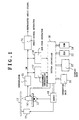
- Figure 1 is a diagram showing the schematic structure of a recorded information reproducing apparatus embodying this invention.
- a recording disk 12 which is a write-once type optical recording medium, such as a CD-R disk, is turned by a spindle motor 11.
- the recording disk 12 has a recording surface which is separated into a program area where audio signals corresponding to individual musical pieces are recorded in a modulated form and a TOC area where various kinds of management information are recorded in a modulated form.
- skip track tracks which are to be excluded from reproduction targets
- a slider mechanism 13 moves a pickup 14 in the radial direction of the recording disk 12.
- the pickup 14 In response to a read start instruction supplied from a system controller 30, the pickup 14 irradiates a read beam on the recording surface of the recording disk 12 and performs photoelectric conversion on the reflected light, thus yielding a read signal. In response to a read stop instruction supplied from the system controller 30, the pickup 14 stops this information reading operation.
- a demodulator 15 digitizes the read signal sent from the pickup 14 to a binary signal.
- the demodulator 15 EFM demodulates on the binary signal, thereby yielding a demodulated digital signal DM.
- the demodulator 15 supplies the demodulated digital signal DM to an audio signal extractor 16, a management information extractor 17 and a sub code extractor 18.
- the audio signal extractor 16 extracts audio signals from the demodulated digital signal DM and outputs the signals as reproduced audio signals.
- the management information extractor 17 extracts the aforementioned management information from the demodulated digital signal DM and sends the information to the system controller 30.
- the sub code extractor 18 extracts the sub codes from the demodulated digital signal DM and sends the sub codes to the system controller 30.
- a servo circuit 19 generates a spindle-motor drive voltage corresponding to a spindle motor turning control signal supplied from the system controller 30.
- the servo circuit 19 applies the spindle-motor drive voltage to the spindle motor 11.
- the servo circuit 19 generates a slider drive voltage corresponding to a slider control signal supplied from the system control circuit 30.
- the servo circuit 19 applies the slider drive voltage to the slider mechanism 13.
- An operation unit 31 generates various instruction signals associated with operations of a disk player, such as a playback operation, a playback stop operation and a track-number designating operation, which are performed by a user, and sends those instruction signals to the system controller 30.
- a display unit 32 displays various kinds of information, such as the total number of musical pieces stored on the recording disk 12, the total time of the musical pieces, the track number of a musical piece which is being currently played and the progressing time of the currently-played musical piece, based on various display instructions supplied from the system controller 30.
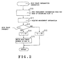
- the system controller 30 executes a sub routine for generating skip track information as shown in Figure 2.
- the system controller 30 supplies the slider control signal to the servo circuit 19 to cause the pickup 14 to read management information from the TOC area of the recording disk 12, and supplies a read start instruction to the pickup 14 (step S10).
- the pickup 14 reads management information from the TOC area of the recording disk 12.
- the management information extractor 17 extracts the management information from the demodulated digital signal DM and sends the management information to the system controller 30.
- the system controller 30 acquires the management information supplied from the management information extractor 17 (step S11), and determines if any track number indicating a skip track is described in this management information (step S12).
- step S12 When no skip track number is described in the management information in step S12, the system controller 30 writes a logic level "0" in a flag register FR (not shown) (step S13).
- step S13 When a skip track number is described in the management information, on the other hand, the system controller 30 writes a logic level "1" in the flag register FR (step S14).
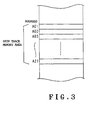
- step S14 the system controller 30 writes the skip track numbers indicating the skip tracks at the respective addresses (addresses "A01" to "A21”) in a skip track memory area in the RAM 34 as shown in Figure 3 (step S15). After executing this step S15 or the aforementioned step S13, the system controller 30 leaves this skip-track-information generating sub routine and returns to a main routine (which will not be discussed in this specification).
- the flag that indicates whether or not any skip track exists on the recording disk 12 is written in the flag register FR.
- the track numbers of the skip tracks are stored at the respective addresses in the skip track memory area in the RAM 34 as shown in Figure 3.
- the system controller 30 sends the slider control signal and the read start instruction respectively to the servo circuit 19 and the pickup 14 in order to continuously play back the individual musical pieces recorded on the recording disk 12, in order, from the track number 1.
- the pickup 14 reads audio signals from the top of the program area of the recording disk 12.
- the audio signal extractor 16 outputs reproduced audio signals, musical piece by musical piece, in order from the one corresponding to the first musical piece.
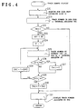
- the system controller 30 executes a sub routine for displaying a track number as shown in Figure 4 every predetermined interval.
- the system controller 30 acquires a sub code supplied from the sub code extractor 18 (step S20). Next, the system controller 30 extracts a track number indicating a currently played track and stores this track number in an internal register TNO (not shown) (step S21). Subsequently, the system controller 30 determines if the value stored in the flag register FR that is set by the execution of the skip-track-information generating sub routine is the logic level "1" (step S22).
- step S22 When having determined in step S22 that the storage content of the flag register FR is the logic level "1" or when having determined that there is a skip track in the recording disk 12, the system controller 30 stores "A01" in an address register AD (not shown) as the initial address in the skip track memory area in the RAM 34 as shown in Figure 3 (step S23). Then, the system controller 30 stores "0" in an internal register T (not shown) as the initial value for the number of skip tracks (step S24). The system controller 30 then reads the track number stored at an address [AD] in the skip track memory area in the RAM 34 as shown in Figure 3 and stores it in an internal register ST (not shown) (step S25). The symbol [AD] is the address that is stored in the address register AD.
- the system controller 30 determines if the track number stored in the internal register ST or the track number of a skip track is smaller than the track number stored in the internal register TNO, i.e., the track number of the currently played track (step S26).
- the system controller 30 adds "1" to the number of skip tracks or the skip track quantity stored in the internal register T and rewrites the memory content of the internal register T to the resultant value as a new skip track quantity (step S27).
- step S27 the system controller 30 determines whether or not the address stored in the address register AD coincides with the last address "A21" in the skip track memory area in the RAM 34 as shown in Figure 3 (step S28).
- step S28 the system controller 30 adds "1" to the address stored in the address register AD and rewrites the memory content of the address register AD to a new address acquired by the addition (step S29).
- step S29 the system controller 30 returns to the aforementioned step S25 and thereafter repeats the above-described operation.
- step S30 When having determined in step S28 that the address stored in the address register AD is identical to the last address "A21", the system controller 30 subtracts the skip track quantity stored in the internal register T from the track number stored in the internal register TNO and rewrites the memory content of the internal register TNO to the resultant value as a new skip track number (step S30).
- step S30 After this step S30 is executed or when it is determined in the aforementioned step S22 that the memory content of the flag register FR is not the logic level "1", i.e., when it is determined that there is not skip track on the recording disk 12, the system controller 30 sends a track-number display instruction to the display unit 32 to display the track number stored in the internal register TNO (step S31). As a result of executing the step S31, the display unit 32 displays the track number stored in the internal register TNO as the track number for the currently played musical piece.
- step S27 the total number of skip tracks having track numbers smaller than the track number of the currently played track that has been acquired from the sub code is counted. Then, the total number of skip tracks is subtracted from the track number of the currently played track, thus yielding a new track number (step S30), and this new track number is displayed on the display unit 32 (step S31).
- new track numbers are respectively assigned to those tracks which result from exclusion of skip tracks from all the tracks where audio signals are recorded.
- the track number display is carried out based on the new track numbers.
- the display unit 32 has a function of automatically displaying the total number of musical pieces stored on the recording disk 12, the total time of the musical pieces and so forth in addition to the above-described function of displaying the track number of the currently played track, the total number of the musical pieces and the total time of the musical pieces which are to be displayed exclude those of the skip tracks. That is, the display unit 32 displays the total number of tracks in a group of tracks resulting from the exclusion of the skip tracks from the entire tracks where audio signals are recorded as the total number of musical pieces and the sum of the playback times of the audio signals recorded on the respective tracks in the track group as the total time of musical pieces.
- the system controller 30 repeatedly executes a sub routine for playing back a skip track as shown in Figure 5 together with the above-described track-number display sub routine every predetermined interval.
- the system controller 30 acquires a sub code supplied from the sub code extractor 18 (step S40).
- the system controller 30 extracts a track number indicating a currently played track from the sub code and stores this track number in the internal register TNO (step S41).
- the system controller 30 stores "A01" in the address register AD as the initial address in the skip track memory area in the RAM 34 as shown in Figure 3 (step S42).
- the system controller 30 reads the skip track number stored at the address [AD] in the skip track memory area in the RAM 34 as shown in Figure 3 and stores it in the internal register ST (step S43).
- [AD] is the address that is stored in the address register AD.
- the system controller 30 determines if the track number of a skip track stored in the internal register ST is identical to the track number stored in the internal register TNO (step S44). When having determined in step S44 that the skip track number stored in the internal register ST is identical to the track number stored in the internal register TNO, the system controller 30 adds "1" to the skip track number stored in the internal register TNO and rewrites the memory content of the internal register TNO to a new track number acquired by the addition (step S45). After this step S45 is executed, the system controller 30 returns to the aforementioned step S42 and thereafter repeats the above-described operation.
- step S44 determines whether or not the address stored in the address register AD coincides with the last address "A21" in the skip track memory area in the RAM 34 as shown in Figure 3 (step S46).
- step S46 determines whether or not the address stored in the address register AD coincides with the last address "A21" in the skip track memory area in the RAM 34 as shown in Figure 3.
- step S47 adds "1" to the address stored in the address register AD and rewrites the memory content of the address register AD to a new address acquired by the addition.
- step S47 After executing this step S47, the system controller 30 returns to the aforementioned step S43 and thereafter repeats the above-described operation.
- step S46 When having determined in step S46 that the address stored in the address register AD is identical to the last address "A21”, the system controller 30 sends the slider control signal to the servo circuit 19 to move the pickup 14 to the position indicated by the track number stored in the internal register TNO (step S48) As a result of executing the step S48, the pickup 14 is moved to the head position of the track indicated by the track number stored in the internal register TNO and restarts reading recorded information from there. After executing this step S48, the system controller 30 leaves this skip-track playback sub routine and returns to the main routine.
- the pickup 14 is forcibly moved to the next track other than any skip track and resumes the playback operation from there. Even if a plurality of recording-failed tracks exist on the recording disk 12, therefore, the musical pieces are played as if the recording-failed tracks never existed.
- the reading position of the pickup 14 comes over a skip track while playing back an audio signal from a track other than a skip track due to a scratch on the recording surface of the recording disk 12, vibration or the like, the following control will be executed.
- the track number of the currently played track that has been read from the recording disk 12 becomes equal to the track number of a skip track, the playback operation is forcibly stopped during which time the display unit 32 makes predetermined image display like "Skip Track".
- the operation unit 31 When the user operates the operation unit 31 to perform a search playback operation of consecutively executing a track number designating operation and a playback instructing operation, the operation unit 31 sends a search track number specified by the track number designating operation to the system controller 30. In response to the search track number, the system controller 30 executes a search playback sub routine as shown in Figure 6.
- the system controller 30 acquires a search track number supplied from the operation unit 31 and stores it in the internal register TNO (step S50).
- the system controller 30 determines if the value stored in the flag register FR that is set by the execution of the skip-track-information generating sub routine is the logic level "1" (step S51).
- the system controller 30 stores "A01" in the address register AD as the initial address in the skip track memory area in the RAM 34 as shown in Figure 3 (step S52).
- the system controller 30 stores "0" in the internal register T as the initial value for the number of skip tracks (step S53).
- the system controller 30 reads the track number stored at an address [AD] in the skip track memory area in the RAM 34 as shown in Figure 3 and stores it in the internal register ST (step S54).
- [AD] is the address that is stored in the address register AD.
- the system controller 30 determines if the track number stored in the internal register ST or the track number of a skip track is smaller than the track number stored in the internal register TNO, i.e., the track number of the currently played track (step S55).
- step S55 When having determined in step S55 that the skip track number is smaller than the track number of the currently played track, the system controller 30 adds "1" to the number of skip tracks or the skip track quantity stored in the internal register T and rewrites the memory content of the internal register T to the resultant value as a new skip track quantity (step S56). After this step S56 is executed or when it is determined in step S55 that the skip track number is not smaller than the track number of the currently played track, the system controller 30 then determines whether or not the address stored in the address register AD coincides with the last address "A21" in the skip track memory area in the RAM 34 as shown in Figure 3 (step S57).
- step S57 When it is not determined in step S57 that the address stored in the address register AD is identical to the last address "A21”, the system controller 30 adds "1" to the address stored in the address register AD and rewrites the memory content of the address register AD to a new address acquired by the addition (step S58). After executing this step S58, the system controller 30 returns to the aforementioned step S54 and thereafter repeats the above-described operation.
- step S59 the system controller 30 adds the skip track quantity stored in the internal register T to the track number stored in the internal register TNO and rewrites the memory content of the internal register TNO to the resultant value as a new track number (step S59).
- step S59 is executed or when it is determined in the aforementioned step S51 that the memory content of the flag register FR is not the logic level "1", i.e., when it is determined that there is not skip track on the recording disk 12, the system controller 30 sends the slider control signal to the servo circuit 19 to move the pickup 14 to the position indicated by the track number stored in the internal register TNO (step S60).
- step S60 the pickup 14 is moved to the head position of the track indicated by the track number that has been specified by the user and restarts reading recorded information from there.
- the system controller 30 leaves this skip-track playback sub routine and returns to the main routine.
- step S56 when skip tracks exist on the recording disk 12, the total number of skip tracks having track numbers smaller than the track number that has been specified by the user is counted (step S56). Then, the total number of skip tracks is added to the track number specified by the user, thus yielding a new track number for the search target (step S59), and playing back the musical pieces starts from there (step S60).
- new track numbers are respectively assigned to those tracks which result from exclusion of skip tracks from all the tracks where audio signals are recorded.
- the search playback is carried out based on the new track numbers. Even if a plurality of skip tracks exist on the recording disk 12, therefore, the number of a desired musical piece in the actual sequence of continuous playback has only to be set as the track number of the track that is designated in the search. This can allow the user to easily perform the search operation without being conscious of the number of skip tracks and the positions of the skip tracks.
- the total number of skip tracks having track numbers smaller than the track number of a currently played track that has been read from the recording disk 12 is counted from time to time (steps S26 and S27 or steps S55 and S56).
- the correlation between the track number of a currently played track and the total number of skip tracks having track numbers smaller than the former track number becomes apparent from the list of the track numbers of skip tracks as shown in Figure 3 which has been obtained as a result of executing the skip-track-information generating sub routine illustrated in Figure 2.
- a conversion table which associates each track number with the total number of skip tracks having track numbers smaller than that each track number is prepared beforehand.
- the total number of skip tracks having track numbers smaller than the track number of a currently played track read from the recording disk 12 is acquired directly and is stored in the internal register T. Then, the flow goes to the process of step S30 (or S59).
- the recorded information reproducing apparatus needs to have such a structure as to be able to assign new track numbers to a group of tracks which result from exclusion of skip tracks from all the tracks where audio signals are recorded.
- a user can easily perform various kinds of operations without being conscious of the existence of a plurality of skip tracks that should be excluded from reproduction targets even if the skip tracks exist on a recording medium.
Landscapes
- Indexing, Searching, Synchronizing, And The Amount Of Synchronization Travel Of Record Carriers (AREA)
- Management Or Editing Of Information On Record Carriers (AREA)
Applications Claiming Priority (2)
| Application Number | Priority Date | Filing Date | Title |
|---|---|---|---|
| JP30530699 | 1999-10-27 | ||
| JP30530699A JP2001126450A (ja) | 1999-10-27 | 1999-10-27 | 記録情報再生装置 |
Publications (2)
| Publication Number | Publication Date |
|---|---|
| EP1096497A2 true EP1096497A2 (fr) | 2001-05-02 |
| EP1096497A3 EP1096497A3 (fr) | 2002-11-27 |
Family
ID=17943522
Family Applications (1)
| Application Number | Title | Priority Date | Filing Date |
|---|---|---|---|
| EP00123313A Withdrawn EP1096497A3 (fr) | 1999-10-27 | 2000-10-26 | Appareil de reproduction d'informations enregistrées |
Country Status (2)
| Country | Link |
|---|---|
| EP (1) | EP1096497A3 (fr) |
| JP (1) | JP2001126450A (fr) |
Family Cites Families (4)
| Publication number | Priority date | Publication date | Assignee | Title |
|---|---|---|---|---|
| JP2887949B2 (ja) * | 1991-06-27 | 1999-05-10 | 松下電器産業株式会社 | 情報記録再生装置、情報再生装置、dma記録方法及びdma検証方法 |
| EP0532998A1 (fr) * | 1991-09-16 | 1993-03-24 | Eastman Kodak Company | Disque compact photographique précisant l'orientation d'image ainsi que procédé et dispositif l'utilisant |
| JPH0850780A (ja) * | 1994-08-05 | 1996-02-20 | Sony Corp | 再生コントローラ、及び再生システム |
| TW286399B (fr) * | 1995-01-03 | 1996-09-21 | Control Alt Design Ltd |
-
1999
- 1999-10-27 JP JP30530699A patent/JP2001126450A/ja active Pending
-
2000
- 2000-10-26 EP EP00123313A patent/EP1096497A3/fr not_active Withdrawn
Also Published As
| Publication number | Publication date |
|---|---|
| EP1096497A3 (fr) | 2002-11-27 |
| JP2001126450A (ja) | 2001-05-11 |
Similar Documents
| Publication | Publication Date | Title |
|---|---|---|
| KR100295219B1 (ko) | 디스크기록장치및디스크기록방법 | |
| EP0310678B1 (fr) | Dispositif et procede d'enregistrement/reproduction de disques | |
| EP0640971B1 (fr) | Appareil de reproduction pour disque optique | |
| KR0126791B1 (ko) | 프로그램 탐색방법 | |
| EP0520381B1 (fr) | Appareil d'enregistrement optique | |
| WO1988006785A1 (fr) | Appareil d'enregistrement de disques | |
| MXPA02004690A (es) | Procesamiento de menu de tres etapas para grabadora de disco digital. | |
| EP0497387B1 (fr) | Méthode pour reproduire l'information enregistrée avec identificateurs de contenu | |
| WO2004061844A1 (fr) | Procede et dispositif d'enregistrement optique | |
| GB2227354A (en) | Record information reproducing system | |
| US4916681A (en) | Apparatus for, and method of, recording undivided compositions in undivided form on a two-sided recording medium | |
| US7620299B2 (en) | Data recording device for recording data in basic recording units | |
| US6510127B1 (en) | Method and apparatus for sequentially reproducing optical recording media | |
| JP3493217B2 (ja) | 情報記録装置 | |
| JP3209369B2 (ja) | 記録再生装置 | |
| EP1667153A1 (fr) | Enregistreur, procede d'enregistrement, et support d'enregistrement porteur de logiciel | |
| JPH11134809A (ja) | 記録再生方法、記録再生装置及び情報記録装置 | |
| JP3368307B2 (ja) | 情報再生装置 | |
| JP2727837B2 (ja) | 光ディスクの再生方法 | |
| JPH05205349A (ja) | デジタル記録再生装置 | |
| JPH09185863A (ja) | ディスク装置 | |
| JP2001126450A (ja) | 記録情報再生装置 | |
| JP3486813B2 (ja) | 情報再生装置 | |
| JP2000339928A (ja) | 画像データ記録装置 | |
| JP3456006B2 (ja) | メディア再生装置 |
Legal Events
| Date | Code | Title | Description |
|---|---|---|---|
| PUAI | Public reference made under article 153(3) epc to a published international application that has entered the european phase |
Free format text: ORIGINAL CODE: 0009012 |
|
| AK | Designated contracting states |
Kind code of ref document: A2 Designated state(s): AT BE CH CY DE DK ES FI FR GB GR IE IT LI LU MC NL PT SE |
|
| AX | Request for extension of the european patent |
Free format text: AL;LT;LV;MK;RO;SI |
|
| PUAL | Search report despatched |
Free format text: ORIGINAL CODE: 0009013 |
|
| AK | Designated contracting states |
Kind code of ref document: A3 Designated state(s): AT BE CH CY DE DK ES FI FR GB GR IE IT LI LU MC NL PT SE |
|
| AX | Request for extension of the european patent |
Free format text: AL;LT;LV;MK;RO;SI |
|
| 17P | Request for examination filed |
Effective date: 20021115 |
|
| AKX | Designation fees paid |
Designated state(s): DE FR GB |
|
| 17Q | First examination report despatched |
Effective date: 20031028 |
|
| GRAP | Despatch of communication of intention to grant a patent |
Free format text: ORIGINAL CODE: EPIDOSNIGR1 |
|
| STAA | Information on the status of an ep patent application or granted ep patent |
Free format text: STATUS: THE APPLICATION IS DEEMED TO BE WITHDRAWN |
|
| 18D | Application deemed to be withdrawn |
Effective date: 20041120 |