EP1096826A2 - Optische Schaltvorrichtung und Verfahren - Google Patents
Optische Schaltvorrichtung und Verfahren Download PDFInfo
- Publication number
- EP1096826A2 EP1096826A2 EP00308815A EP00308815A EP1096826A2 EP 1096826 A2 EP1096826 A2 EP 1096826A2 EP 00308815 A EP00308815 A EP 00308815A EP 00308815 A EP00308815 A EP 00308815A EP 1096826 A2 EP1096826 A2 EP 1096826A2
- Authority
- EP
- European Patent Office
- Prior art keywords
- optical
- parallel
- routing
- unit
- optical channel
- Prior art date
- Legal status (The legal status is an assumption and is not a legal conclusion. Google has not performed a legal analysis and makes no representation as to the accuracy of the status listed.)
- Withdrawn
Links
Images


Classifications
-
- G—PHYSICS
- G02—OPTICS
- G02B—OPTICAL ELEMENTS, SYSTEMS OR APPARATUS
- G02B6/00—Light guides; Structural details of arrangements comprising light guides and other optical elements, e.g. couplings
- G02B6/24—Coupling light guides
- G02B6/26—Optical coupling means
- G02B6/35—Optical coupling means having switching means
- G02B6/354—Switching arrangements, i.e. number of input/output ports and interconnection types
- G02B6/3542—Non-blocking switch, e.g. with multiple potential paths between multiple inputs and outputs, the establishment of one switching path not preventing the establishment of further switching paths
-
- G—PHYSICS
- G02—OPTICS
- G02B—OPTICAL ELEMENTS, SYSTEMS OR APPARATUS
- G02B6/00—Light guides; Structural details of arrangements comprising light guides and other optical elements, e.g. couplings
- G02B6/24—Coupling light guides
- G02B6/26—Optical coupling means
- G02B6/28—Optical coupling means having data bus means, i.e. plural waveguides interconnected and providing an inherently bidirectional system by mixing and splitting signals
- G02B6/293—Optical coupling means having data bus means, i.e. plural waveguides interconnected and providing an inherently bidirectional system by mixing and splitting signals with wavelength selective means
- G02B6/29302—Optical coupling means having data bus means, i.e. plural waveguides interconnected and providing an inherently bidirectional system by mixing and splitting signals with wavelength selective means based on birefringence or polarisation, e.g. wavelength dependent birefringence, polarisation interferometers
-
- G—PHYSICS
- G02—OPTICS
- G02B—OPTICAL ELEMENTS, SYSTEMS OR APPARATUS
- G02B6/00—Light guides; Structural details of arrangements comprising light guides and other optical elements, e.g. couplings
- G02B6/24—Coupling light guides
- G02B6/26—Optical coupling means
- G02B6/28—Optical coupling means having data bus means, i.e. plural waveguides interconnected and providing an inherently bidirectional system by mixing and splitting signals
- G02B6/293—Optical coupling means having data bus means, i.e. plural waveguides interconnected and providing an inherently bidirectional system by mixing and splitting signals with wavelength selective means
- G02B6/29379—Optical coupling means having data bus means, i.e. plural waveguides interconnected and providing an inherently bidirectional system by mixing and splitting signals with wavelength selective means characterised by the function or use of the complete device
- G02B6/29395—Optical coupling means having data bus means, i.e. plural waveguides interconnected and providing an inherently bidirectional system by mixing and splitting signals with wavelength selective means characterised by the function or use of the complete device configurable, e.g. tunable or reconfigurable
-
- G—PHYSICS
- G02—OPTICS
- G02B—OPTICAL ELEMENTS, SYSTEMS OR APPARATUS
- G02B6/00—Light guides; Structural details of arrangements comprising light guides and other optical elements, e.g. couplings
- G02B6/24—Coupling light guides
- G02B6/26—Optical coupling means
- G02B6/35—Optical coupling means having switching means
- G02B6/354—Switching arrangements, i.e. number of input/output ports and interconnection types
- G02B6/356—Switching arrangements, i.e. number of input/output ports and interconnection types in an optical cross-connect device, e.g. routing and switching aspects of interconnecting different paths propagating different wavelengths to (re)configure the various input and output links
-
- G—PHYSICS
- G02—OPTICS
- G02F—OPTICAL DEVICES OR ARRANGEMENTS FOR THE CONTROL OF LIGHT BY MODIFICATION OF THE OPTICAL PROPERTIES OF THE MEDIA OF THE ELEMENTS INVOLVED THEREIN; NON-LINEAR OPTICS; FREQUENCY-CHANGING OF LIGHT; OPTICAL LOGIC ELEMENTS; OPTICAL ANALOGUE/DIGITAL CONVERTERS
- G02F1/00—Devices or arrangements for the control of the intensity, colour, phase, polarisation or direction of light arriving from an independent light source, e.g. switching, gating or modulating; Non-linear optics
- G02F1/29—Devices or arrangements for the control of the intensity, colour, phase, polarisation or direction of light arriving from an independent light source, e.g. switching, gating or modulating; Non-linear optics for the control of the position or the direction of light beams, i.e. deflection
- G02F1/31—Digital deflection, i.e. optical switching
-
- H—ELECTRICITY
- H04—ELECTRIC COMMUNICATION TECHNIQUE
- H04Q—SELECTING
- H04Q11/00—Selecting arrangements for multiplex systems
- H04Q11/0001—Selecting arrangements for multiplex systems using optical switching
- H04Q11/0005—Switch and router aspects
-
- G—PHYSICS
- G02—OPTICS
- G02B—OPTICAL ELEMENTS, SYSTEMS OR APPARATUS
- G02B6/00—Light guides; Structural details of arrangements comprising light guides and other optical elements, e.g. couplings
- G02B6/24—Coupling light guides
- G02B6/26—Optical coupling means
- G02B6/35—Optical coupling means having switching means
- G02B6/351—Optical coupling means having switching means involving stationary waveguides with moving interposed optical elements
- G02B6/3522—Optical coupling means having switching means involving stationary waveguides with moving interposed optical elements the optical element enabling or impairing total internal reflection
-
- G—PHYSICS
- G02—OPTICS
- G02B—OPTICAL ELEMENTS, SYSTEMS OR APPARATUS
- G02B6/00—Light guides; Structural details of arrangements comprising light guides and other optical elements, e.g. couplings
- G02B6/24—Coupling light guides
- G02B6/26—Optical coupling means
- G02B6/35—Optical coupling means having switching means
- G02B6/354—Switching arrangements, i.e. number of input/output ports and interconnection types
- G02B6/3544—2D constellations, i.e. with switching elements and switched beams located in a plane
- G02B6/3546—NxM switch, i.e. a regular array of switches elements of matrix type constellation
-
- G—PHYSICS
- G02—OPTICS
- G02B—OPTICAL ELEMENTS, SYSTEMS OR APPARATUS
- G02B6/00—Light guides; Structural details of arrangements comprising light guides and other optical elements, e.g. couplings
- G02B6/24—Coupling light guides
- G02B6/26—Optical coupling means
- G02B6/35—Optical coupling means having switching means
- G02B6/354—Switching arrangements, i.e. number of input/output ports and interconnection types
- G02B6/3544—2D constellations, i.e. with switching elements and switched beams located in a plane
- G02B6/3548—1xN switch, i.e. one input and a selectable single output of N possible outputs
-
- G—PHYSICS
- G02—OPTICS
- G02B—OPTICAL ELEMENTS, SYSTEMS OR APPARATUS
- G02B6/00—Light guides; Structural details of arrangements comprising light guides and other optical elements, e.g. couplings
- G02B6/24—Coupling light guides
- G02B6/26—Optical coupling means
- G02B6/35—Optical coupling means having switching means
- G02B6/3564—Mechanical details of the actuation mechanism associated with the moving element or mounting mechanism details
- G02B6/3582—Housing means or package or arranging details of the switching elements, e.g. for thermal isolation
-
- G—PHYSICS
- G02—OPTICS
- G02B—OPTICAL ELEMENTS, SYSTEMS OR APPARATUS
- G02B6/00—Light guides; Structural details of arrangements comprising light guides and other optical elements, e.g. couplings
- G02B6/24—Coupling light guides
- G02B6/26—Optical coupling means
- G02B6/35—Optical coupling means having switching means
- G02B6/3594—Characterised by additional functional means, e.g. means for variably attenuating or branching or means for switching differently polarized beams
-
- G—PHYSICS
- G02—OPTICS
- G02F—OPTICAL DEVICES OR ARRANGEMENTS FOR THE CONTROL OF LIGHT BY MODIFICATION OF THE OPTICAL PROPERTIES OF THE MEDIA OF THE ELEMENTS INVOLVED THEREIN; NON-LINEAR OPTICS; FREQUENCY-CHANGING OF LIGHT; OPTICAL LOGIC ELEMENTS; OPTICAL ANALOGUE/DIGITAL CONVERTERS
- G02F1/00—Devices or arrangements for the control of the intensity, colour, phase, polarisation or direction of light arriving from an independent light source, e.g. switching, gating or modulating; Non-linear optics
- G02F1/01—Devices or arrangements for the control of the intensity, colour, phase, polarisation or direction of light arriving from an independent light source, e.g. switching, gating or modulating; Non-linear optics for the control of the intensity, phase, polarisation or colour
- G02F1/13—Devices or arrangements for the control of the intensity, colour, phase, polarisation or direction of light arriving from an independent light source, e.g. switching, gating or modulating; Non-linear optics for the control of the intensity, phase, polarisation or colour based on liquid crystals, e.g. single liquid crystal display cells
- G02F1/137—Devices or arrangements for the control of the intensity, colour, phase, polarisation or direction of light arriving from an independent light source, e.g. switching, gating or modulating; Non-linear optics for the control of the intensity, phase, polarisation or colour based on liquid crystals, e.g. single liquid crystal display cells characterised by the electro-optical or magneto-optical effect, e.g. field-induced phase transition, orientation effect, guest-host interaction or dynamic scattering
- G02F1/139—Devices or arrangements for the control of the intensity, colour, phase, polarisation or direction of light arriving from an independent light source, e.g. switching, gating or modulating; Non-linear optics for the control of the intensity, phase, polarisation or colour based on liquid crystals, e.g. single liquid crystal display cells characterised by the electro-optical or magneto-optical effect, e.g. field-induced phase transition, orientation effect, guest-host interaction or dynamic scattering based on orientation effects in which the liquid crystal remains transparent
- G02F1/141—Devices or arrangements for the control of the intensity, colour, phase, polarisation or direction of light arriving from an independent light source, e.g. switching, gating or modulating; Non-linear optics for the control of the intensity, phase, polarisation or colour based on liquid crystals, e.g. single liquid crystal display cells characterised by the electro-optical or magneto-optical effect, e.g. field-induced phase transition, orientation effect, guest-host interaction or dynamic scattering based on orientation effects in which the liquid crystal remains transparent using ferroelectric liquid crystals
-
- G—PHYSICS
- G02—OPTICS
- G02F—OPTICAL DEVICES OR ARRANGEMENTS FOR THE CONTROL OF LIGHT BY MODIFICATION OF THE OPTICAL PROPERTIES OF THE MEDIA OF THE ELEMENTS INVOLVED THEREIN; NON-LINEAR OPTICS; FREQUENCY-CHANGING OF LIGHT; OPTICAL LOGIC ELEMENTS; OPTICAL ANALOGUE/DIGITAL CONVERTERS
- G02F1/00—Devices or arrangements for the control of the intensity, colour, phase, polarisation or direction of light arriving from an independent light source, e.g. switching, gating or modulating; Non-linear optics
- G02F1/29—Devices or arrangements for the control of the intensity, colour, phase, polarisation or direction of light arriving from an independent light source, e.g. switching, gating or modulating; Non-linear optics for the control of the position or the direction of light beams, i.e. deflection
- G02F1/31—Digital deflection, i.e. optical switching
- G02F1/311—Cascade arrangement of plural switches
-
- H—ELECTRICITY
- H04—ELECTRIC COMMUNICATION TECHNIQUE
- H04Q—SELECTING
- H04Q11/00—Selecting arrangements for multiplex systems
- H04Q11/0001—Selecting arrangements for multiplex systems using optical switching
- H04Q11/0005—Switch and router aspects
- H04Q2011/0007—Construction
- H04Q2011/0024—Construction using space switching
-
- H—ELECTRICITY
- H04—ELECTRIC COMMUNICATION TECHNIQUE
- H04Q—SELECTING
- H04Q11/00—Selecting arrangements for multiplex systems
- H04Q11/0001—Selecting arrangements for multiplex systems using optical switching
- H04Q11/0005—Switch and router aspects
- H04Q2011/0007—Construction
- H04Q2011/0035—Construction using miscellaneous components, e.g. circulator, polarisation, acousto/thermo optical
-
- H—ELECTRICITY
- H04—ELECTRIC COMMUNICATION TECHNIQUE
- H04Q—SELECTING
- H04Q11/00—Selecting arrangements for multiplex systems
- H04Q11/0001—Selecting arrangements for multiplex systems using optical switching
- H04Q11/0005—Switch and router aspects
- H04Q2011/0052—Interconnection of switches
- H04Q2011/0058—Crossbar; Matrix
-
- H—ELECTRICITY
- H04—ELECTRIC COMMUNICATION TECHNIQUE
- H04Q—SELECTING
- H04Q11/00—Selecting arrangements for multiplex systems
- H04Q11/0001—Selecting arrangements for multiplex systems using optical switching
- H04Q11/0062—Network aspects
- H04Q2011/0073—Provisions for forwarding or routing, e.g. lookup tables
Definitions
- the present invention relates to a routing optical matrix switching method and a device for optical communication. More specifically, the preferred embodiment relates to a routing optical matrix switching method and a device for WDM optical communication networks.
- optical matrix switching devices available on the market are switched between input fibers and output fibers with high precision machine-driving fiber or driving optical prism, referring to the product catalogs of The USA Dicon fiber Optics Inc, E-TEK Inc and Canada JDS, and also seeing "Optical Components for WDM Lightwave Networks". Proceedings of The IEEE, Vol.85, No.8, p1274-1307, Aug, 1997.
- the switching rate of the above mentioned machine-driving optical matrix switching is about 0.5-0.7 second. It is difficult and complex to perform M ⁇ N all-optical cross-connection, although easily achieving 1 ⁇ N or 2 ⁇ N all-optical cross connection.
- the M X N all-optical cross-connection with the method of conventional optical Crossbar switching networks causes very large insertion loss in the process of 1 X N fan-out and M X 1 fan-in.
- the present invention seeks to provide improved switching.
- an optical matrix switching device as specified in claim 2.
- the preferred embodiment can provide all-optical matrix switching which is suitable for all-optical cross connect equipment, optical adding/dropping multiplex OADM and optical wavelength route OXC equipment in high-speed D-WDM optical communication networks.
- a bidirectional and a unidirectional optical matrix switching device can be developed.
- Preferred bidirectional and unidirectional optical matrix switching devices are structured with a parallel routing optical channel and a parallel optical channel routing combination, wherein
- the optical matrix-switching device may also have one or more of the following features:
- the said optical switching array can be an optical switching of movable wavelength plate array, or a liquid-crystal optical switching device as well.
- the crystal prism can be a trapezoid polarization prism as well as a birefringence crystal prism.
- a unidirectional optical matrix-switching device is simple, moreover, both the last stage of optical switching array and the parallel plane crystal units can be left out in routing combination unit of parallel optical channels.
- the M ⁇ N optical matrix switching method and device of the preferred embodiments have the following various advantages: low insertion loss, low polarization dependent loss, low cross-talk, simplified, flexible, and good scalability.
- the M ⁇ N optical matrix switching device can widely be used for varieties of all-optical cross connection, optical add/drop OADM and optical wavelength route OXC equipment in the field of WDM optical communication.
- Figure 1 is a schematic diagram showing an embodiment of 4 X 4 optical matrix switch.
- Figures 2(A) and 2(B) are schematic diagrams showing a bidirectional 4 X 4 optical matrix switching device.
- Figures 2a(A) and 2a(B) are schematic diagrams showing a unidirectional 4 X 4 optical matrix switching device.
- Figure 3 is a schematic diagram showing an optical collimated unit of one dimensional fiber array.
- Figure 4 is a schematic diagram showing a parallel plane crystal unit.
- Figure 5 is a schematic diagram showing an embodiment 4 X 4 parallel routing optical channel unit.
- Figure 6 is a schematic diagram showing a parallel routing optical channel unit of using a trapezoid polarization prism as a crystal prism.
- Figure 7 illustrates polarized orientations of various signal beams in the parallel routing optical channel.
- Figures 8(A) and 8(B) are schematic diagrams showing a parallel routing optical channel unit using a birefringence crystal prism as a crystal prism.
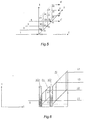
- Figure 9 is a schematic diagram showing a ⁇ /2 wavelength plate array.
- Figure 10 is a schematic diagram showing a routing combination unit of parallel optical channel of using a trapezoid polarization prism as a crystal prism.
- Figure 11 illustrates polarized orientations of various signal beams and a control procedure in routing combination unit of parallel optical channel.
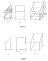
- Figures 12(A) and 12(B) are schematic diagrams showing a routing combination unit of parallel optical channel using a birefringence crystal prism as a crystal prism.
- Figure 13 illustrates a design scheme of a trapezoid polarization prism.
- Figure 14 illustrates a design scheme of a trapezoid prism crystal.
- Figure 15 illustrates the structure of optical switching device with movable wavelength plate array.
- routing combination unit of parallel optical channel having passed through a ⁇ /2 wavelength plate array A and a routing combination unit of parallel optical channel IV, four parallel output optical channels in the x direction are routing combined into one optical channel, such as a routing combination 13+23+33+43; and then through a reverse parallel plane crystal unit V and a coupling unit of one dimension fiber array VI, the routing combining signal beam is regenerated as original random polarization signal beams and coupled into output fiber F3' to output.
- Figure 2(A) shows the part of routing parallel optical channel, where I, II, and III are the same as the above mentioned.
- Figure 2(B) shows the part of parallel optical channel routing combination in a bidirection optical matrix switching device, where A, IV, V and VI are also the same as the previously mentioned.
- Figure 2a(A) shows the part of routing parallel optical channel in an unidirection optical matrix-witching device, which is the same as that 2(A) in the bidirection optical matrix switching.
- Figure 2a(B) shows the part of parallel optical channel routing combination in an unidirection optical matrix-switching, obtained by removing both the last stage of optical switching array from unit IV and the parallel plane crystal unit V in Figure 2(B).
- Figure 3 shows a 4 ⁇ 1 optical collimated unit of one dimension fiber array and a couple unit of fiber array. Having stripped its cladding, fiber is inserted into the micro-capillary M with outside diameter d 0 and solidified with glue, and then its end surfaces are polished and are make AR coating to perform the micro-capillary with fiber tail.
- a collimated GRIN micro-lense T which is provided with an outer diameter equal to that of the micro-capillary and the same wavelength as communication signal beam, is selected and arranged one by one inside the same one V-grooves. Thus, a signal beam from one fiber is converted into a collimated light beam.
- Figure 4 is shows a parallel plane crystal unit composed of four rectangle parallel plane crystals B 1 , B 2 , B 3 , B 4 and two wavelength plates W 1 , W 2 .
- a one-dimension array of four collimated beams entering crystal B 1 is split into ordinary polarization and extraordinary polarization light beams (o-signal beam and e-signal beam) to pass through crystal B 1 .
- the e-beam propagates through crystal B 1 in upward-deflection direction, and is separated with space ⁇ apart from o-beam on the output end surface in upward vertical direction, and then o-beam and e-beam propagate in parallel.
- wavelength plate W 1 can convert o-beam into e-beam, and e-beam into o-beam.
- the o-beam passes through crystal B 2 in straight line, and e-beam propagates in downward-deflection direction through crystal B 2 and is separated with space 2 ⁇ apart from the o-beam on the output end surface of B 2 in downward vertical direction. And then, o-beam and e-beam propagate in parallel.
- the wavelength plate W2 is combined with both upper half and lower half parts with the same thickness, in which the upper half part is ⁇ /2 wavelength plate and the lower half part is a glass base plate of parallel plane.
- the o-beam in the upper half part of the wavelength plate W2 is changed into an e-beam and the e-beam in the lower half part of the wavelength plate W2 keep unchanged, to realize the parallel propagation of all e-beams.
- the crystals B 3 and B 4 are of the same kind and of the same thickness.
- the crystal axis orientation of crystals B 3 and B 4 are symmetrical with each other, and the bottom surface of crystals B 3 is totally overlapped with the upper surface of crystal B 4 .
- the e-beam in the upper half vertically incidents into the upper crystal B3, then is downwards deflected near to the bottom surface of the upper crystal and finally exits from the output end surface.
- both e-beams in the upper and the bottom crystals are incorporated into almost-one beam of e-polarization light to propagate in parallel.
- the crystal unit makes four collimated random polarization beams from four fibers to converts into four collimated linear polarization light beams of almost-one beam.
- FIG. 5 A schematic diagram of a 4 ⁇ 4 routing parallel optical channel unit of the present invention is shown as in Figure 5.
- Four collimated input signal light beams 1, 2, 3 and 4 from a 1 ⁇ 4 fiber array are arranged in the x direction. Having passed through a parallel plate crystal unit, four random polarization beams are converted complete linear e-polarization beams.
- each input signal beam is provided with four parallel optical channels placed in the y direction.
- Output ends with order numbers corresponding to each input signal light beam, called the output number ends are 1-11, 12, 13, 14; 2-21, 22, 23, 24; 3-31, 32, 33, 34; 4-41, 42, 43, 44.
- each signal beam can select one of four relevant optical channels to reach the output number end.
- Figure 6 shows a 4 ⁇ 4 routing parallel optical channel unit consisting of two trapezoid polarization prisms P1, P2 and two pieces of optical switching array LC1, LC2.
- the polarizing orientation of e signal beam 1, 2, 3 and 4, generated from the unit for converting the random polarization light into the complete polarization light, is in conformity to that of p beam inside trapezoid polarization prism, referred to as vertical polarization.
- Optical switching array LC1 is an array of 4 ⁇ 1 cells, expressed as [ M (1) / 11 M (1) / 21 M (1) / 31 M (1) / 41].
- Optical switching array LC2 is an array of 4 ⁇ 2 cells, expressed as Under the control of an external control system, each cell of optical switching array can be in two states corresponding to behaviors of glass medium and ⁇ /2 wavelength plate, or three states corresponding to natures of glass medium, ⁇ /2 wavelength plate and ⁇ /4 wavelength plate.
- a trapezoid polarization prism P 1 can provide two parallel optical channels for an input parallel signal beam i in the y direction.
- the signal beam i is controlled to select one or both of parallel optical channel i1 and i2 for transmission.
- a signal light beam i passes through the cell M (1) / i1
- the cell M (1) / i 1 of switching LC1 behaves as glass medium which keeps e-beam no change
- signal light beam i will be transmitted via the optical channel i1.
- the cell M (1) / i 1 of switching LC1 behaves as a ⁇ /2 wavelength plate for converting an e-beam into an o-beam, signal light beam i will be transmitted via the optical channel i2.
- the cell M (1) / i 1 of switching LC1 behaves as a ⁇ /4 wavelength plate, signal light beam i will be split into two signal beams of the equal intensity and be transmitted via two parallel optical channels i1 and i2, respectively.
- the trapezoid polarization prism P 2 makes it available to transmit each of input signal light beams i1 and i2 via two parallel optical channels in the y direction, i1--i1, i3, and i2--i2, i4.
- e-beam keeps its own polarization orientation no change, and thus signal light beam i1 will be transmitted via the optical channel i1.
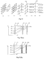
- Fig. 7 (a) illustrates random polarization signal light beams from a fiber array.
- Fig. 7 (b) illustrates linear polarization e-beams converted by crystal units.
- Fig. 7 (c) illustrates the cells of optical switching LC1.
- FIG. 7(d) illustrates the polarization orientations of signal beams after passing through trapezoid polarization prism P 1 .
- FIG. 7(e) illustrates the cells of optical switching LC2.
- FIG. 7(f) illustrates the polarization orientations of signal beams after passing through trapezoid polarization prism P 2 .
- Fig. 7 (a) illustrates random polarization signal light beams from a fiber array.
- Fig. 7 (b) illustrates linear polarization e-beams converted by crystal units.
- Fig. 7 (c) illustrates the cells of optical switching LC1.
- FIG. 7(d) illustrates the polarization orientations of signal beams after passing through trap
- the collimated signal beams of random polarization from a fiber array via the unit of converting a random polarization beam into a linear polarization beam, can be formed into four collimated linear polarization e-beams, expressed as [ A e / 11 A e / 21 A e / 31 A e / 41].
- the four signal light beams respectively pass through the corresponding cells of optical switching LC1 [M (1) / 11 M (1) / 21 M (1) / 31 M (1) / 41] and trapezoid polarization prism P 1 , and the relative routing and broadcast procedure are expressed as follow
- a 4 ⁇ 2 array of collimated linear polarization signal beams passes through the corresponding cells of optical switching LC2 and trapezoid polarization prism P 2 , and the relative routing and broadcast procedure are expressed as follow:
- a 4 ⁇ 4 routing parallel optical channel unit is structured with birefringence crystal prisms and optical switching arrays.
- a birefringence crystal prism can use trapezoid prism crystals as shown in Figure 8(A) or rectangle parallel plane crystals as shown in Figure 8(B).
- two birefringence crystal prisms C 1 and C 2 will replace two trapezoid polarization prisms P 1 and P 2 shown in Figure 6, respectively.
- an incident beam i is provided with two available transmission paths. If the incident beam i is an o-polarization beam, it will be transmitted along the direction of the straight-line i1. If it is an e-polarization beam, the incident beam i propagates through crystal C 1 in upward-deflection direction, and is deflected with spacing d 0 apart from the o-beam on the output end surface, and then propagates in the direction i2. As a result, two parallel optical channels for respectively transmitting o-beam and e-beam are established.
- the thickness of crystal C 2 is twice that of crystal C 1 , two parallel optical channels are divided into four channels. If the light beam i1 is an o-polarization beam, it will pass through the crystal C 2 in straight line. If the beam i is an e-polarization beam, it propagates through crystal C 2 in upward-deflection direction, and is deflected with space 2d 0 apart from the o-beam on the output end surface upwards, and then parallelly propagates in the direction i3. Similarly, the light beam i2 through the crystal C 2 establishes parallel optical channels i2 and i4.
- routing parallel optical channel unit with birefringence crystals In routing parallel optical channel unit with birefringence crystals, the routing principle and control method of parallel optical channels are totally the same as routing parallel optical channel system with trapezoid polarization prisms. But for two kinds of optical channel system mentioned above, respective signal beam in the parallel optical channels takes totally opposite polarization orientation.
- the mathematics equations of routing and broadcast procedure of 4 ⁇ 4 parallel optical channels are expressed as (la) and (2b).
- the routing and broadcast procedure of 4 ⁇ 4 parallel optical channels is applicable to a 2 m ⁇ 2 n optical matrix switching system with birefringence crystals.
- the signal beam i from an input fiber may propagate along four parallel optical channels arranged in the y direction, and then reaches the respective output order number end, 1--11, 12, 13, 14; 2--21, 22, 23, 24; 3--31, 32, 33, 34; 4--41, 42, 43, 44.
- the polarization orientations of signal beams at the respective output order number end are shown as in Figure 7.
- four signal beams from the four input fibers shall be transmitted into the same output port, and have to be coupled into the same one output fiber, i.e., 11, 21, 31, 41---1'; 12, 22, 32, 42--2'; 13, 23, 33, 43--3'; 14, 24, 34, 44--4'.
- the optical matrix-switching device serving for an all-optical cross connection system must be a non-block system of the destination addresses. Although signals at each input port are possible to be transmitted to any output port, one output port is connected only with one input port within the identical period.
- the present invention provides a method for routing combining parallel optical channels in need of reaching to the same output port into the identical parallel optical channel, so that signal light beams from any input port can be coupled high-effectively to any output port.
- a routing combination unit of parallel optical channels is structured with two trapezoid polarization prisms P 3 , P 4 and two optical switching arrays LC3, LC4.
- the orientation of the trapezoid polarization prism is located in the x direction, and is made an angle of 90° to trapezoid polarization prisms of routing parallel optical channel system shown in Figure 6.
- the polarization orientation of optical channels in routing combination unit of parallel optical channels in Figure 10 is at an angle of 90° to that in routing parallel optical channel system shown in Figure 6.
- the input optical channels 1i, 2i, 3i and 4i indicate four parallel optical channels shown in Figure 7(f), respectively, which are 1i-- I I, 12, 13, 14; 2i--21, 22, 23, 24; 3i--31, 32, 33, 34; 4i--41, 42, 43, 44.
- the polarization orientation of each signal beam in routing combination procedure is illustrated in Figure 11.
- the polarization orientations of signal beams in the 4 ⁇ 4 parallel optical channels are the same as that shown in Figure 11(a).
- the signal beams in two optical channels can simultaneously be passes through the identical cell of optical switching array LC3, A 0 / 11 + A e / 31 - M (3) / 31, , A 0 / 21 + A e / 41 - M (3) / 31 , A 0 / 12 + A e / 32 -M (3) / 32, A 0 / 22 + A e / 42 - M (3) / 33, A 0 / 13 + A e / 33 - M (3) / 33 , A 0 / 23 + A e / 43 - M (3) / 43 , A 0 / 14 + A e / 34 - M (3) / 34 , and A 0 / 24 + A e / 44 - M (3) / 44.
- the above method, in which parallel optical channels are routing combined into one parallel optical channel, is applicable to a 2 m ⁇ 2 n optical matrix switching system.
- a 2 ⁇ 2 optical matrix switching needs one set of trapezoid polarization prism and optical switching array pair.
- a 4 ⁇ 4 system needs two sets of trapezoid polarization prism and optical switching array pair.
- a 2 ⁇ 8 system needs one set of trapezoid polarization prism and optical switching array pair.
- a 2 m ⁇ 2 n system needs m sets of trapezoid polarization prism and optical switching array pair.
- the optical switching array device is identical to the optical switching array in routing parallel optical channel system, and may be an optical switching of movable wavelength plate array as well as a liquid-crystal optical switching array device (including a Ferro-liquid crystal optical switching array device).
- a routing combination unit of parallel optical channel is also structured with birefringence crystal prisms.
- a birefringence crystal prism can use trapezoid prism crystals shown in Figure 12(A) or rectangle parallel plane crystals shown in Figure 12(B).
- a 4 ⁇ 4 routing combination unit of parallel optical channel of using a birefringence crystal prism is structured with two sets of birefringence crystal prisms and optical switching arrays. In this system, two birefringence crystal prisms C 3 and C 4 will replace two trapezoid polarization prisms P 2 and P 4 shown in Figure 10, respectively.
- o-polarization beam 4i passes through the crystal in straight line, but e-polarization beam 4i vertically come into the crystal and propagates in upward-deflection direction.
- beams 3i and 4i are completely combined into one parallel optical channel 4i.
- routing combination unit of parallel optical channel unit with birefringence crystals the principle of routing-combination and control system is totally similar to that for routing combination unit of parallel optical channel with trapezoid polarization prisms.
- the respective signal beams in the parallel optical channels takes totally the opposite polarization orientation. Consequently, in the routing combination unit with birefringence crystals, the mathematics equations of the routing combination procedure of parallel optical channels are expressed as (3c) and (4d) hereinafter.
- the routing combination procedure of 4 ⁇ 4 parallel optical channels is applicable to a 2 m ⁇ 2 n optical matrix switching system with birefringence crystals.
- Optical elements in optical matrix switching device are designed specifically as follow:
- FIG 13 Designs of trapezoid polarization prisms P 1 , P 2 , P 3 , P 4 in the above-mentioned figures are shown in Figure 13.
- the prisms are combined with parallelogram prism ABHG and corner cubic prism AF'B or corner cubic trapezoid prism EFBA, shown in Figure 13(a).
- Figure 13(c) is a three-dimensional scheme view of prisms shown in Figure 13(a).
- ABCD is a polarization film, of which the bandwidth is larger than wavelength range of signal beams transmitted.
- the space between input fibers is do.
- the width S of the prism depends on the number of the input, the output fibers and the spacing d 0 between fibers in Figure 1.
- the width S of the prism is regularly M ⁇ d 0 + S 0 , N ⁇ d 0 + S 0 , where S 0 is dependent on requirement of system design.
- the width S of the prism depends on the number M of input fibers and the spacing d 0 between fibers in Figures 8(A), 8(B), 12(A) and 12(B).
- the width S of the prism is regularly M ⁇ d 0 +S 0 , where S 0 is dependent on requirement of system design.
- the height of birefringence crystals is dependent on the input light beam array.
- crystals C 1 and C 4 if the incident beam i is an o-polarization beam, it will be transmitted in straight line.
- the incident light beam i is an e-polarization beam, it propagates through the crystals in upward- (or downward-) deflection direction, and is deflected with spacing d 0 upwards apart from the o-beam on the output port surface of the crystal C 1 , and then parallel optical channel transmission are established.
- the thickness of the crystals C 2 and C 3 is twice that of crystals C 1 and C 4 , two parallel optical channels are split into four parallel optical channels.
- the incident light beam i is an o-polarization beam
- it will pass through the crystals C 2 and C 3 in straight line.
- the beam i is an e-polarization beam
- it propagates through the crystals in upward- (or downward-) deflection direction, and is deflected with spacing 2d 0 apart from the o-beam on the output port surface of C 2 and C 3 upwards, and then propagates in the parallel direction.
- Optical switching device with movable wavelength plate array is configured with N glass base plates of which the width is slightly smaller than do. ⁇ /2 or ⁇ /4 wavelength plates are attached on the different light-passing areas with spacing d 0 on each base plate. Under the control of external electric signal commands, each glass base plate can be rapidly translated between two states corresponding to behaviors of glass medium and ⁇ /2 wavelength plate, or three states corresponding to natures of regular glass medium, ⁇ /2 wavelength plate and ⁇ /4 wavelength plate.
- Figure 15 illustrates one of the above-mentioned structures, in which (a) is the configuration of optical switching devices LC1 and LC4 with movable wavelength plate array, (b) is the configuration of optical switching devices LC2 and LC3 with movable wavelength plate array, and (c) is the configuration of optical switching devices LC3 and LC4 with movable wavelength plate array.
- Optical switching device can be a liquid-crystal optical switching array (including Ferro-liquid-crystal optical switching array with 50 ⁇ s switching rate, in which each cell can be transformed between two or three states above-mentioned rapidly.
- the routing procedure of transmitting signal beams from each input port to any output port is dependent on the states of optical switching cells in four switching array devices.
- Each optical switching cell state is dependent on four matrix equations described as follow: With four equations above-mentioned, under the external voltage control command, the state M j / i of each optical switching cell in the routing procedure of transmitting signal beams from each input port to any output port is obtained.
- the state M j / i of respective optical switching cell in four optical switching devices is A 1 ⁇ B 1 : M (1) 11 A e 11 ⁇ A e 11 ⁇ M (2) 11 A e 11 ⁇ A e 11 ⁇ M (3) 31 A o 11 ⁇ A o 11 ⁇ M (4) 41 A o 11 ⁇ A e 11 A 1 ⁇ B 2 : M (1) 11 A e 11 ⁇ A e 12 ⁇ M (2) 12 A o 12 ⁇ A e 11 ⁇ M (3) 32 A o 12 ⁇ A o 12 ⁇ M (4) 42 A o 21 ⁇ A e 12 A 1 ⁇ B 3 : M (1) 11 A e 11 ⁇ A e 11 ⁇ M (2) 11 A o 11 ⁇ A e 13 ⁇ M (3) 33 A o 13 ⁇ A o 13 ⁇ M (4) 43 A o 13 ⁇ A e 13 A 1 ⁇ B 4 : M (1)
- the state M j / i of respective optical switching cell in four optical switching devices is A 2 ⁇ B 1 : M (1) 21 A e 21 ⁇ A e 21 ⁇ M (2) 21 A e 21 ⁇ A e 21 ⁇ M (3) 41 A o 21 ⁇ A e 21 ⁇ M (4) 41 A o 21 ⁇ A e 21 A 2 ⁇ B 2 : M (1) 21 A e 21 ⁇ A o 22 ⁇ M (2) 22 A o 22 ⁇ A e 22 ⁇ M (3) 42 A o 22 ⁇ A e 22 ⁇ M (4) 42 A o 22 ⁇ A e 22 A 2 ⁇ B 3 : M (1) 21 A e 21 ⁇ A e 21 ⁇ M (2) 21 A e 21 ⁇ A o 23 ⁇ M (3) 43 A o 23 ⁇ A e 23 ⁇ M (4) 43 A e 23 ⁇ A e 23 A 2 ⁇ B 4 : M (1)
- the state M j / i of respective optical switching cell in four optical switching devices is A 3 ⁇ B 1 : M (1) 31 A e 31 ⁇ A e 31 ⁇ M (2) 31 A e 31 ⁇ A e 31 ⁇ M (3) 31 A e 31 ⁇ A o 21 ⁇ M (4) 41 A o 31 ⁇ A e 31 A 3 ⁇ B 2 : M (1) 31 A e 31 ⁇ A o 32 ⁇ M (2) 32 A o 32 ⁇ A e 32 ⁇ M (3) 32 A e 32 ⁇ A o 32 ⁇ M (4) 42 A o 32 ⁇ A e 32 A 3 ⁇ B 3 : M (1) 31 A e 31 ⁇ A e 31 ⁇ M (2) 31 A e 31 ⁇ A o 33 ⁇ M (3) 33 A o 33 ⁇ A o 33 ⁇ M (4) 43 A o 33 ⁇ A e 33 A 3 ⁇ B 4 : M (1)
- the state M j / i of respective optical switching cell in four optical switching devices is A 4 ⁇ B 1 : M (1) 41 A e 41 ⁇ A e 41 ⁇ M (2) 41 A e 41 ⁇ A e 41 ⁇ M (3) 41 A e 41 ⁇ A e 41 ⁇ M (4) 41 A e 41 ⁇ A e 41 A 4 ⁇ B 2 : M (1) 41 A e 41 ⁇ A o 42 ⁇ M (2) 42 A o 42 ⁇ A e 42 ⁇ M (3) 42 A e 42 ⁇ A e 42 ⁇ M (4) 42 A e 42 ⁇ A e 42 A 4 ⁇ B 3 : M (1) 41 A e 41 ⁇ A e 41 ⁇ M (2) 41 A e 41 ⁇ A o 43 ⁇ M (3) 43 A e 43 ⁇ A e 43 ⁇ M (4) 43 A e 43 ⁇ A e 43 A 4 ⁇ B 4 : M (1)
- the routing procedure of transmitting signal beams from each input port to any output port is dependent on the states of optical switching cells in four switching array devices.
- Each optical switching cell state is dependent from four matrix equations described as follow:
- the state M j / i of each optical switching cell in the routing procedure of transmitting signal beams from each input port to any output port is obtained.
- the state M j / i of respective optical switching cell in four optical switching devices is A 1 ⁇ B 1 : M (1) 11 A e 11 ⁇ A o 11 ⁇ M (2) 11 A o 11 ⁇ A o 11 ⁇ M (3) 31 A e 11 ⁇ A e 11 ⁇ M (4) 41 A e 11 ⁇ A e 11 A 1 ⁇ B 2 : M (1) 11 A e 11 ⁇ A o 12 ⁇ M (2) 12 A o 12 ⁇ A o 12 ⁇ M (3) 32 A e 12 ⁇ A e 12 ⁇ M (4) 42 A e 12 ⁇ A e 12 A 1 ⁇ B 3 : M (1) 11 A e 11
- the state M j / i of respective optical switching cell in four optical switching devices is A 2 ⁇ B 1 : M (1) 21 A e 21 ⁇ A o 21 ⁇ M (2) 21 A o 21 ⁇ A o 21 ⁇ M (3) 41 A e 21 ⁇ A o 21 ⁇ M (4) 41 A o 21 ⁇ A e 21 A 2 ⁇ B 2 : M (1) 21 A e 21 ⁇ A e 22 ⁇ M (2) 22 A e 22 ⁇ A o 22 ⁇ M (3) 42 A e 22 ⁇ A o 22 ⁇ M (4) 42 A o 22 ⁇ A e 22 A 2 ⁇ B 3 : M (1) 21 A e 21 ⁇ A o 21 ⁇ M (2) 21 A o 21 ⁇ A e 23 ⁇ M (3) 43 A e 23 ⁇ A o 23 ⁇ M (4) 43 A o 23 ⁇ A e 23 A 2 ⁇ B 4 : M (1)
- the state M j / i of respective optical switching cell in four optical switching devices is A 3 ⁇ B 1 : M (1) 31 A e 31 ⁇ A o 31 ⁇ M (2) 31 A o 31 ⁇ A o 31 ⁇ M (3) 31 A o 31 ⁇ A e 31 ⁇ M (4) 41 A e 31 ⁇ A e 31 A 3 ⁇ B 2 : M (1) 31 A e 31 ⁇ A e 32 ⁇ M (2) 32 A e 32 ⁇ A o 32 ⁇ M (3) 32 A o 32 ⁇ A o 32 ⁇ M (4) 42 A o 32 ⁇ A e 32 A 3 ⁇ B 3 : M (1) 31 A e 31 ⁇ A o 31 ⁇ M (2) 31 A o 31 ⁇ A o 33 ⁇ M (3) 33 A o 33 ⁇ A e 33 ⁇ M (4) 43 A e 33 ⁇ A e 33 A 3 ⁇ B 4 : M (1)
- the state M j / i of respective optical switching cell in four optical switching devices is A 4 ⁇ B 1 : M (1) 41 A e 41 ⁇ A o 41 ⁇ M (2) 41 A o 41 ⁇ A o 41 ⁇ M (3) 41 A o 41 ⁇ A o 41 ⁇ M (4) 41 A o 41 ⁇ A e 41 A 4 ⁇ B 2 : M (1) 41 A e 41 ⁇ A e 42 ⁇ M (2) 42 A e 42 ⁇ A o 42 ⁇ M (3) 42 A o 42 ⁇ A o 42 ⁇ M (4) 42 A o 42 ⁇ A e 42 A 4 ⁇ B 3 : M (1) 41 A e 41 ⁇ A o 41 ⁇ M (2) 41 A o 41 ⁇ A e 43 ⁇ M (3) 43 A o 43 ⁇ A o 43 ⁇ M (4) 43 A o 43 ⁇ A e 43 A 4 ⁇ B 4 : M (1)
Landscapes
- Physics & Mathematics (AREA)
- General Physics & Mathematics (AREA)
- Optics & Photonics (AREA)
- Engineering & Computer Science (AREA)
- Computer Networks & Wireless Communication (AREA)
- Nonlinear Science (AREA)
- Optical Communication System (AREA)
- Optical Couplings Of Light Guides (AREA)
- Use Of Switch Circuits For Exchanges And Methods Of Control Of Multiplex Exchanges (AREA)
Applications Claiming Priority (2)
| Application Number | Priority Date | Filing Date | Title |
|---|---|---|---|
| CN99116685.XA CN1120992C (zh) | 1999-10-08 | 1999-10-08 | 2m×2n光学交叉连接方法及其器件 |
| CN99116685 | 1999-10-08 |
Publications (2)
| Publication Number | Publication Date |
|---|---|
| EP1096826A2 true EP1096826A2 (de) | 2001-05-02 |
| EP1096826A3 EP1096826A3 (de) | 2002-12-18 |
Family
ID=5279466
Family Applications (1)
| Application Number | Title | Priority Date | Filing Date |
|---|---|---|---|
| EP00308815A Withdrawn EP1096826A3 (de) | 1999-10-08 | 2000-10-06 | Optische Schaltvorrichtung und Verfahren |
Country Status (3)
| Country | Link |
|---|---|
| US (1) | US6798938B1 (de) |
| EP (1) | EP1096826A3 (de) |
| CN (1) | CN1120992C (de) |
Families Citing this family (5)
| Publication number | Priority date | Publication date | Assignee | Title |
|---|---|---|---|---|
| JP2002148435A (ja) * | 2000-11-10 | 2002-05-22 | Fdk Corp | 偏光分離合成素子及びそれを用いる光デバイス |
| US6834137B2 (en) * | 2001-12-05 | 2004-12-21 | Lightwaves 2020, Inc. | Cholesteric liquid crystal cell devices and systems |
| US8213795B2 (en) * | 2007-05-09 | 2012-07-03 | University Of Central Florida Research Foundation, Inc. | Systems and methods of polarization time coding for optical communications |
| US10698291B2 (en) * | 2018-05-22 | 2020-06-30 | Quanergy Systems, Inc. | Integrated phased array for two dimensional beem steering through constructive interference by light emitting structures comprising select elements on a two-dimensional lattice |
| CN120165780B (zh) * | 2025-02-10 | 2026-01-02 | 国网冀北电力有限公司信息通信分公司 | 一种多通道长距离光模块 |
Family Cites Families (7)
| Publication number | Priority date | Publication date | Assignee | Title |
|---|---|---|---|---|
| US4461543A (en) * | 1982-03-26 | 1984-07-24 | Sperry Corporation | Electro optic switch |
| US4989941A (en) * | 1988-03-18 | 1991-02-05 | The United States Of America As Represented By The Secretary Of The Air Force | Normal incidence optical switches using ferroelectric liquid crystals |
| US4948229A (en) * | 1988-03-18 | 1990-08-14 | The United States Of America As Represented By The Secretary Of The Air Force | Optical switches using ferroelectric liquid crystals |
| US5235452A (en) * | 1989-06-02 | 1993-08-10 | Minister Of The Post Telecommunications And Space (Centre National D'etudes Des Telecommunications) | Process and switching matrix apparatus for optical transmission of signals by self-heterodyning |
| JPH03204621A (ja) * | 1990-01-08 | 1991-09-06 | Nippon Telegr & Teleph Corp <Ntt> | 光マトリックススイッチ |
| US5771320A (en) * | 1996-04-30 | 1998-06-23 | Wavefront Research, Inc. | Optical switching and routing system |
| US6134358A (en) * | 1998-08-27 | 2000-10-17 | Chorum Technologies Inc. | N x N switch array with reduced components |
-
1999
- 1999-10-08 CN CN99116685.XA patent/CN1120992C/zh not_active Expired - Fee Related
-
2000
- 2000-10-06 EP EP00308815A patent/EP1096826A3/de not_active Withdrawn
- 2000-10-11 US US09/686,525 patent/US6798938B1/en not_active Expired - Fee Related
Also Published As
| Publication number | Publication date |
|---|---|
| CN1251905A (zh) | 2000-05-03 |
| US6798938B1 (en) | 2004-09-28 |
| CN1120992C (zh) | 2003-09-10 |
| EP1096826A3 (de) | 2002-12-18 |
Similar Documents
| Publication | Publication Date | Title |
|---|---|---|
| CN1307449C (zh) | 重新路由光信号的光学器件、方法和光纤波长开关 | |
| US7236660B2 (en) | Reconfigurable optical add-drop module, system and method | |
| US7088882B2 (en) | Wavelength cross-connect | |
| US7373037B2 (en) | Compact wavelength-selective optical crossconnect | |
| US11516562B2 (en) | Core selective switch and optical node device | |
| Tsai et al. | MEMS optical switches and interconnects | |
| US6449407B1 (en) | Optical switch having equalized beam spreading in all connections | |
| US6956987B2 (en) | Planar lightwave wavelength blocker devices using micromachines | |
| EP3021595B1 (de) | Vorrichtung für optische vernetzung | |
| US7321704B2 (en) | Wavelength cross connect with per port performance characteristics | |
| EP1096826A2 (de) | Optische Schaltvorrichtung und Verfahren | |
| Lin et al. | Optical crossconnects for high‐capacity lightwave networks | |
| CN117031636B (zh) | 一种Twin结构的波长选择开关及智能光网络器件 | |
| Maruno et al. | Integrated PLC-based modules with multi-chip configuration | |
| Itoh | Compact ROADM devices based on PLC technology |
Legal Events
| Date | Code | Title | Description |
|---|---|---|---|
| PUAI | Public reference made under article 153(3) epc to a published international application that has entered the european phase |
Free format text: ORIGINAL CODE: 0009012 |
|
| AK | Designated contracting states |
Kind code of ref document: A2 Designated state(s): AT BE CH CY DE DK ES FI FR GB GR IE IT LI LU MC NL PT SE |
|
| AX | Request for extension of the european patent |
Free format text: AL;LT;LV;MK;RO;SI |
|
| PUAL | Search report despatched |
Free format text: ORIGINAL CODE: 0009013 |
|
| RIC1 | Information provided on ipc code assigned before grant |
Free format text: 7H 04Q 11/00 A, 7G 02B 6/35 B, 7G 02F 1/31 B |
|
| AK | Designated contracting states |
Kind code of ref document: A3 Designated state(s): AT BE CH CY DE DK ES FI FR GB GR IE IT LI LU MC NL PT SE |
|
| AX | Request for extension of the european patent |
Free format text: AL;LT;LV;MK;RO;SI |
|
| AKX | Designation fees paid | ||
| REG | Reference to a national code |
Ref country code: DE Ref legal event code: 8566 |
|
| STAA | Information on the status of an ep patent application or granted ep patent |
Free format text: STATUS: THE APPLICATION IS DEEMED TO BE WITHDRAWN |
|
| 18D | Application deemed to be withdrawn |
Effective date: 20030619 |