EP1097508B2 - Verfahren und gerät zur kompensierung der verzerrung in iq modulatoren - Google Patents
Verfahren und gerät zur kompensierung der verzerrung in iq modulatoren Download PDFInfo
- Publication number
- EP1097508B2 EP1097508B2 EP99928091A EP99928091A EP1097508B2 EP 1097508 B2 EP1097508 B2 EP 1097508B2 EP 99928091 A EP99928091 A EP 99928091A EP 99928091 A EP99928091 A EP 99928091A EP 1097508 B2 EP1097508 B2 EP 1097508B2
- Authority
- EP
- European Patent Office
- Prior art keywords
- signal
- function
- weighted
- distortion
- signals
- Prior art date
- Legal status (The legal status is an assumption and is not a legal conclusion. Google has not performed a legal analysis and makes no representation as to the accuracy of the status listed.)
- Expired - Lifetime
Links
- 238000000034 method Methods 0.000 title claims description 20
- 230000006870 function Effects 0.000 claims description 70
- 238000001228 spectrum Methods 0.000 claims description 9
- 239000002131 composite material Substances 0.000 claims description 8
- 238000012545 processing Methods 0.000 claims description 8
- 238000012360 testing method Methods 0.000 claims description 5
- 230000003044 adaptive effect Effects 0.000 description 2
- 230000001447 compensatory effect Effects 0.000 description 2
- 238000012937 correction Methods 0.000 description 2
- 230000010363 phase shift Effects 0.000 description 2
- 230000004044 response Effects 0.000 description 2
- 102000003712 Complement factor B Human genes 0.000 description 1
- 108090000056 Complement factor B Proteins 0.000 description 1
- 238000012888 cubic function Methods 0.000 description 1
- 230000001934 delay Effects 0.000 description 1
- 230000003111 delayed effect Effects 0.000 description 1
- 238000013461 design Methods 0.000 description 1
- 230000000694 effects Effects 0.000 description 1
- 238000001914 filtration Methods 0.000 description 1
Images


Classifications
-
- H—ELECTRICITY
- H03—ELECTRONIC CIRCUITRY
- H03F—AMPLIFIERS
- H03F1/00—Details of amplifiers with only discharge tubes, only semiconductor devices or only unspecified devices as amplifying elements
- H03F1/32—Modifications of amplifiers to reduce non-linear distortion
- H03F1/3241—Modifications of amplifiers to reduce non-linear distortion using predistortion circuits
-
- H—ELECTRICITY
- H03—ELECTRONIC CIRCUITRY
- H03C—MODULATION
- H03C3/00—Angle modulation
- H03C3/38—Angle modulation by converting amplitude modulation to angle modulation
- H03C3/40—Angle modulation by converting amplitude modulation to angle modulation using two signal paths the outputs of which have a predetermined phase difference and at least one output being amplitude-modulated
-
- H—ELECTRICITY
- H03—ELECTRONIC CIRCUITRY
- H03D—DEMODULATION OR TRANSFERENCE OF MODULATION FROM ONE CARRIER TO ANOTHER
- H03D3/00—Demodulation of angle-, frequency- or phase- modulated oscillations
- H03D3/007—Demodulation of angle-, frequency- or phase- modulated oscillations by converting the oscillations into two quadrature related signals
- H03D3/009—Compensating quadrature phase or amplitude imbalances
-
- H—ELECTRICITY
- H04—ELECTRIC COMMUNICATION TECHNIQUE
- H04L—TRANSMISSION OF DIGITAL INFORMATION, e.g. TELEGRAPHIC COMMUNICATION
- H04L27/00—Modulated-carrier systems
- H04L27/32—Carrier systems characterised by combinations of two or more of the types covered by groups H04L27/02, H04L27/10, H04L27/18 or H04L27/26
- H04L27/34—Amplitude- and phase-modulated carrier systems, e.g. quadrature-amplitude modulated carrier systems
- H04L27/36—Modulator circuits; Transmitter circuits
- H04L27/366—Arrangements for compensating undesirable properties of the transmission path between the modulator and the demodulator
- H04L27/367—Arrangements for compensating undesirable properties of the transmission path between the modulator and the demodulator using predistortion
- H04L27/368—Arrangements for compensating undesirable properties of the transmission path between the modulator and the demodulator using predistortion adaptive predistortion
Definitions
- the present invention relates to a method and apparatus for compensating for phase and amplitude distortion in an output signal generated when a complex signal is modulated onto a radio frequency carrier signal using IQ modulation techniques or when a complex signal is demodulated from a radio frequency carrier signal, again using IQ modulation techniques.
- the complex signal is broken up into its real part, the I-signal and an imaginary part, the Q-signal.
- the I-signal is amplitude modulated onto a local oscillator signal using a first double sideband mixer and the Q-signal is amplitude modulated onto a phase quadrature local oscillator signal (90° out of phase with the local oscillator signal) using a second double sideband mixer.
- the outputs of the two double sideband mixers are then combined and the resultant modulated carrier signal carries the complex signal as amplitude and phase variations.
- the I and Q-signals can be recovered by demodulation in an IQ demodulation arrangement with respect to a local oscillator signal and a phase quadrature local oscillator signal respectively.
- the IQ modulator When a complex signal is modulated onto a carrier using an IQ modulator, the IQ modulator will behave substantially linearly when the input signal levels are low. As the level of the input signals increase an IQ modulator will become more non-linear and the output modulated carrier signal becomes distorted. Intermodulation distortion becomes a problem because some of the third order intermodulation products will have a frequency which is close to that of the desired signals and so are difficult to remove by filtering.
- Cubic predistortion has been used in an IQ modulator by cubic predistortion of the complex signal. This is disclosed in the article entitled “ Transmitter linearisation using composite modulation feedback” in Volume 32, Number 23 of Electronics Letters dated 7 November 1996 in which the cubic predistortion is combined with a negative feedback loop. However, this cubic predistortion is of the opposite sign in upper and lower sidebands whereas the IQ modulator phase distortion is of the same sign in the upper and lower sidebands. This means that cancellation of distortion in both sidebands simultaneously is not possible.
- the object of the present invention is to provide a distortion compensating arrangement for applications in which a complex signal is modulated onto a single carrier signal or in which a complex signal is recovered from a single carrier signal, using IQ modulation techniques and which overcomes the problems discussed above.
- the present invention provides distortion compensating apparatus for use in IQ modulation and demodulation techniques wherein a first distortion arrangement distorts the I-signal by adding (8) to the I-signal a first 3rd or higher order polynomial weighted function of the I-signal and a first 3rd or higher order polynomial weighted function of the Q-signal and a second distortion arrangement distorts the Q-signal by adding (16) to the Q-signal a second 3rd or higher order polynomial weighted function of the I-signal and a second 3rd or higher order polynomial weighted function of the Q-signal, such that the weighted functions of the I-signal are independent of the Q-signal and the weighted functions of the Q-signat are independent of the I-signal.
- any distortion for improving linearity has distorted both components of the complex signal identically, whereas according to the present invention the distortion takes place on the I and Q components independently. This makes it possible to compensate for distortion in both sidebands simultaneously.
- embodiments of the present invention comprises a distortion compensating apparatus as claimed in claim 1.
- the function is a polynomial and preferably the polynomial is cubic.
- Cubic distortion is the dominant type of distortion for most components and so a compensating cubic polynomial is preferred.
- approximations to a cubic distortion which effectively applies an approximation to a cubic polynomial to the I and Q-signals, may be simpler to implement. In certain cases higher order polynomials may be appropriate to provide distortion compensation.
- the apparatus according to the present invention can be used to predistort I-and Q-signals which are to be input into an IQ modulator or to post distort I and Q-signals which have been recovered from an IQ demodulator.
- At least one multiplier is used to multiply the functions of the I-and Q-signals by a weighting factor. This provides the weighting ready for the subsequent summation. Then, it is preferred that at least one adder adds selected outputs of the one or more multipliers in order to perform the weighted summations.
- a first multiplier multiplies the function of the I-signal with a first weighting factor and a second multiplier multiplies the function of the Q-signal with a second weighting factor and an adder adds the output from the first multiplier and the second multiplier to the I-signal.
- a third multiplier multiplies the function of the I-signal with a third weighting factor and a fourth multiplier multiplies the function of the Q-signal with a fourth weighting factor and an adder adds the output from the third multiplier and the fourth multiplier to the Q-signal.
- At least one of the multipliers may be implemented as a look up table and at least one of the operator arrangements can be implemented as a look up table in order to efficiently implement the circuitry required to perform the weighted summation.
- the present invention further provides a device for adjusting a composite IQ modulator or demodulator, which composite IQ modulator or demodulator comprises a distortion compensating apparatus as described above and an IQ modulator or demodulator.
- the adjusting device comprises a signal source for generating test signals, a spectrum analyser for measuring the level of distortion in the output of the IQ modulator or demodulator under test and a control processor for controlling the weighting factors. In this way the weighting factors can be varied until the distortion level is minimised.
- the present invention also provides a method for improving linearity in IQ modulation and demodulation techniques wherein the I-signal is distorted by adding (8) to the I-signal a first weighted 3rd or higher order polynomial function of the I-signal and a first weighted 3rd or higher order polynomial function of the Q-signal and the Q-signal is distorted by adding (16) to the Q-signal a second weighted 3rd or higher order polynomial function of the I-signal and a second weighted 3rd or higher order polynomial function of the Q-signal, such that the function of the I-signal is independent of the Q-signal and the function of the Q-signal is independent of the I-signal.
- the function is a polynomial and preferably the polynomial is cubic. According to a preferred embodiment of the method at least one of the functions of the signals is multiplied by one or more weighting factors. Thereafter selected multiplied functions of the signals can be added to perform the weighted summation.
- the distortion compensation according to the present invention can be carried out by digital or analogue processing of the I and Q-signals or by a combination of digital and analogue processing stages.
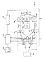
- Figure 1 which shows a distortion arrangement (4) arranged to predistort the I and Q-signals before they are input into the I and Q arms respectively of an IQ modulator (2).
- the I and Q-signals are generated digitally.
- the distortion arrangement (4) according to the present invention is used to predistort the I and Q-signals to compensate for third order distortion in the output modulated carrier signal.
- a constant weighting factor A is then applied to the signal (I-signal) 3 at multiplier (12) and the resulting signal A.(I-signal) 3 is input into the first adder (8).
- a constant weighting factor B is applied to the signal (I-signal) 3 at multiplier (14) and the resulting signal B.(I-signal) 3 is input into a second adder (16).
- a constant weighting factor C is then applied to the signal (Q-signal) 3 at multiplier (22) and the resulting signal C.(Q-signal) 3 is input into the second adder (16).
- a constant weighting factor D is applied to the signal (Q-signal) 3 at multiplier (24) and the resulting signal D.(Q-signal) 3 is input into the first adder (8).
- signals I-signal, A.(I-signal) 3 and D.(Q-signal) 3 are input into the first adder (8) and signals Q-signal, C.(Q-signal) 3 and B.(I-signal) 3 are input into the second adder (16).
- the multipliers (12, 14, 22 and 24) can be implemented efficiently as look-up tables. Also because the correction factors are small, few significant bits are required in the cubing operation performed by the cubing blocks (10,18). This considerably simplifies the implementation of the cubing operation. As the output of each cubing block (10,18) is the function of a single variable, the cubing block can also be implemented as a look-up table.
- the IQ modulator (2) comprises radio frequency local oscillator (30) which generates a signal of, for example, 4GHz which is input into a 90° hybrid (32) which supplies the in-phase or I local oscillator signal to double sideband mixer (34) and the in-quadrature or Q local oscillator signal to double sideband mixer (36).
- the predistorted I-signal (I-signal') from the first adder (8) is modulated onto the I local oscillator signal at mixer (34) and the predistorted Q-signal (Q-signal') from the second adder (16) is modulated onto the Q local oscillator signal at mixer (36). These are then added in the combiner (46).
- the distortion arrangement (4) to predistort the I and Q-signals which are input into the IQ modulator (2) the third order distortion in the modulated carrier signal output from the IQ modulator can be effectively suppressed.
- the double sideband mixers (34) and (36) in the IQ-modulator (2) are working with sufficiently low signal levels that fifth and higher order distortion can be ignored.
- A, B, C and D in the distortion arrangement (4) have to be determined for the particular IQ modulator (2) for which the arrangement (4) is intended, because each design of IQ modulator will apply different levels of third order distortion as it processes the input signals.
- Figure 2 shows equipment suitable for adjusting a composite device comprising the distortion arrangement (4) and an IQ modulator, such as the IQ modulator (2) shown in Figure 1 .
- the test equipment comprises a distortion arrangement (4) as described above in relation for Figure 1 , a signal source (55), a control processor (52), a spectrum analyser (53) and optionally a display (54).
- the signal source (55) generates suitable IQ test signals which would include a single complex tone, where the spectrum analyser looks for harmonic distortion, and a pair of complex tones, where the spectrum analyser would look for intermodulation distortion between the two tones.
- the I and Q-signais are input into the distortion arrangement (4) and predistorted as described above in relation to Figure 1 .
- the predistorted signals I-signal' and Q-signal' are then input into the respective inputs of the IQ modulator (2).
- the IQ modulator (2) modulates the I and Q-signals onto a single carrier and the modulated output of the IQ modulator (2) is input into the spectrum analyser (53).
- the spectrum analyser is arranged to measure the level of third order distortion in the signal output from the IQ modulator (2).
- the control processor (52) in response to the output from the spectrum analyser (53) generates and controls the weighting factor signals A, B, C and D which provide the weighting in the summation performed by the distortion arrangement (4).
- the control processor (52) is arranged to systematically alter the signals A, B, C and D until the distortion products measured by the spectrum analyser (53) are minimised.
- the values of A, B, C and D which achieve the maximum reduction of distortion products are then the optimum levels which can be fixed for commercially manufactured implementations of the distortion arrangement (4) adapted to the IQ modulator (2).
- the optimisation of A, B, C and D can also be done by an individual observing the screen (54) and manually altering the levels of A, B, C and D input into the distortion arrangement (4) by the control processor (52).
- Figure 3 shows the distortion arrangement (4) being used to post distort the I and Q-signals recovered from a radio frequency carrier which has undergone demodulation in an IQ demodulation arrangement.
- the radio frequency carrier is input at (100).
- the carrier prior to its broadcast, was modulated with I and Q-signals by the IQ modulator (2) shown in Figure 2 .
- a local oscillator (102) generates the reference radio frequency signal of 4GHz and a 90° hybrid (104) generates the local oscillator signal I and the phase quadrature local oscillator signal Q.
- Double sideband mixer (106) then mixes the carrier signal with the local oscillator signal and the resultant signal is passed through low pass filter (116) to recover the demodulated I-signal".
- Double sideband mixer (108) mixes the carrier signal with the phase quadrature local oscillator signal and the resultant signal is passed through low pass filter (120) to recover demodulated signal Q-signal".
- I-signal and Q-signal will have phase and amplitude distortions applied to them already by the mixing stage of the demodulation process and so the compensatory distortion applied by the arrangement (4) will be less effective to reduce intermodulation distortion than when the undistorted signals I-signal and Q-signal are input into the arrangement (4) as described above in relation to Figure 1 .
- the signals I-signal” and Q-signal" are processed by the distortion arrangement (4) as described above in relation to Figure 1 .
- the post distorted signal I-signal''' and Q-signal''' are input into signal processor (114) for further processing.
Landscapes
- Engineering & Computer Science (AREA)
- Power Engineering (AREA)
- Physics & Mathematics (AREA)
- Nonlinear Science (AREA)
- Computer Networks & Wireless Communication (AREA)
- Signal Processing (AREA)
- Digital Transmission Methods That Use Modulated Carrier Waves (AREA)
- Amplifiers (AREA)
Claims (20)
- Verzerrungskorrekturvorrichtung zur Verzerrungskorrektur in IQ-Modulatoren und - Demodulatoren, wobei eine erste Verzerrungsanordnung das I-Signal verzerrt, indem zu dem I-Signal eine erste gewichtete Polynomfunktion dritter oder höherer Ordnung des I-Signals und eine erste gewichtete Polynomfunktion dritter oder höherer Ordnung des Q-Signals addiert (8) wird, und wobei eine zweite Verzerrungsanordnung das Q-Signal verzerrt, indem zu dem Q-Signal eine zweite gewichtete Polynomfunktion dritter oder höherer Ordnung des I-Signals und eine zweite gewichtete Polynomfunktion dritter oder höherer Ordnung des Q-Signals addiert (16) wird, so dass die gewichteten Funktionen des I-Signals unabhängig von dem Q-Signal sind, und so dass die gewichteten Funktionen des Q-Signals unabhängig von dem I-Signal sind.
- Vorrichtung nach Anspruch 1, wobei die Vorrichtung folgendes umfasst:eine erste Operatoranordnung (10) zum Erzeugen der genannten Funktion des I-Signals;eine zweite Operatoranordnung (18) zum Erzeugen der genannten Funktion des Q-Signals; undeine Signalverarbeitungseinrichtung (8, 12, 24; 14, 16, 22) zur Durchführung einer gewichteten Summierung des I-Signals, der Funktion des I-Signals und der Funktion des Q-Signals, so dass eine verzerrungskorrigierte Ausgabe des I-Signals erzeugt wird, sowie zur Durchführung einer gewichteten Summierung des Q-Signals, der Funktion des Q-Signals und der Funktion des I-Signals, so dass eine verzerrungskorrigierte Ausgabe des Q-Signals erzeugt wird.
- Vorrichtung nach Anspruch 1, wobei das Polynom kubisch ist.
- Vorrichtung nach einem der vorstehenden Ansprüche, wobei die verzerrten I- und Q-Signale durch einen IQ-Modulator (2) auf ein einziges Trägersignal amplitudenmoduliert werden.
- Vorrichtung nach einem der Ansprüche 1 bis 3, wobei die I- und Q-Signale durch eine IQ-Demodulationsanordnung (102, 104, 106, 108) von einem einzelnen Trägersignal demoduliert werden.
- Vorrichtung nach einem der vorstehenden Ansprüche, wobei mindestens ein Multiplizierer (12, 14, 22, 24) eingesetzt wird, um die Funktion der I- und Q-Signale mit einem Gewichtungsfaktor zu multiplizieren.
- Vorrichtung nach Anspruch 6, wobei mindestens ein Addierer (8, 16) ausgewählte Ausgaben des einen oder der mehreren Multiplizierer addiert, um gewichtete Summierungen durchzuführen.
- Vorrichtung nach einem der vorstehenden Ansprüche, wobei ein erster Multiplizierer (12, 24) die Funktion des I-Signals mit einem ersten konstanten Gewichtungsfaktor multipliziert, und wobei ein zweiter Multiplizierer die Funktion des Q-Signals mit einem zweiten konstanten Gewichtungsfaktor multipliziert.
- Vorrichtung nach einem der vorstehenden Ansprüche, wobei ein dritter Multiplizierer (22, 14) die Funktion des Q-Signals mit einem dritten konstanten Gewichtungsfaktor multipliziert, und wobei ein vierter Multiplizierer die Funktion des I-Signals mit einem vierten konstanten Gewichtungsfaktor multipliziert.
- Vorrichtung nach Anspruch 8, wobei ein Addierer (8) die Ausgabe des ersten Multiplizierers und des zweiten Multiplizierers zu dem I-Signal addiert.
- Vorrichtung nach Anspruch 9, wobei ein Addierer (16) die Ausgabe des dritten Multiplizierers und des vierten Multiplizierers zu dem Q-Signal addiert.
- Vorrichtung nach einem der Ansprüche 6 bis 11, wobei mindestens einer der Multiplizierer als eine Verweistabelle implementiert ist.
- Vorrichtung nach einem der Ansprüche 2 bis 11, wobei mindestens eine der Operatoranordnungen als eine Verweistabelle implementiert ist.
- Verfahren zur Verbesserung der Linearität von IQ-Modulatoren und -Demodulatoren, wobei das I-Signal verzerrt wird, indem zu dem I-Signal eine erste gewichtete Polynomfunktion dritter oder höherer Ordnung des I-Signals und eine erste gewichtete Polynomfunktion dritter oder höherer Ordnung des Q-Signals addiert (8) wird, und wobei das Q-Signal verzerrt wird, indem zu dem Q-Signal eine zweite gewichtete Polynomfunktion dritter oder höherer Ordnung des I-Signals und eine zweite gewichtete Polynomfunktion dritter oder höherer Ordnung des Q-Signals addiert (16) wird, so dass die gewichteten Funktionen des I-Signals unabhängig von dem Q-Signal sind, und so dass die gewichteten Funktionen des Q-Signals unabhängig von dem I-Signal sind.
- Verfahren nach Anspruch 14, wobei das Verfahren folgendes umfasst:das Erzeugen (10) der genannten Funktion des I-Signals;das Erzeugen (18) der genannten Funktion des Q-Signals;das Durchführen (8, 12, 24) einer gewichteten Summierung des I-Signals, der Funktion des I-Signals und der Funktion des Q-Signals, so dass eine verzerrungskorrigierte Ausgabe des I-Signals erzeugt wird, sowie das Durchführen (16, 14, 22) einer gewichteten Summierung des Q-Signals, der Funktion des Q-Signals und der Funktion des I-Signals, so dass eine verzerrungskorrigierte Ausgabe des Q-Signals erzeugt wird.
- Verfahren nach Anspruch 14, wobei das Polynom kubisch ist.
- Verfahren nach einem der Ansprüche 14 bis 16, wobei mindestes eine der Funktionen der Signale mit einem oder mehreren Gewichtungsfaktoren multipliziert (12, 14, 22, 24) wird.
- Verfahren nach Anspruch 17, wobei ausgewählte multiplizierte Funktionen der Signale addiert (8, 12) werden, so dass die gewichtete Summierung durchgeführt wird.
- Vorrichtung zur Anpassung eines zusammengesetzten IQ-Modulators oder - Demodulators, wobei der zusammengesetzte IQ-Modulator oder -Demodulator eine Verzerrungskorrekturvorrichtung nach einem der Ansprüche 1 bis 13 sowie einen IQ-Modulator (2) oder -Demodulator (102, 104, 106, 108) umfasst, wobei die Vorrichtung eine Spektrumanalyseeinrichtung (53) zum Messen der Höhe der Verzerrung in der Ausgabe eines zusammengesetzten IQ-Modulators oder -Demodulators umfasst, sowie einen Steuerprozessor (52) zur Steuerung der Gewichtung der Funktionen der I- und Q-Signale in einem zusammengesetzten IQ-Modulator und -Demodulator.
- Vorrichtung nach Anspruch 19, wobei diese eine Signalquelle (55) zur Erzeugung von Testsignalen aufweist.
Applications Claiming Priority (3)
| Application Number | Priority Date | Filing Date | Title |
|---|---|---|---|
| GB9815342 | 1998-07-16 | ||
| GB9815342A GB2339657B (en) | 1998-07-16 | 1998-07-16 | Method and apparatus for compensating for distorsion in IQ modulators |
| PCT/GB1999/001996 WO2000004634A1 (en) | 1998-07-16 | 1999-06-25 | Method and apparatus for compensating for distortion in iq modulators |
Publications (3)
| Publication Number | Publication Date |
|---|---|
| EP1097508A1 EP1097508A1 (de) | 2001-05-09 |
| EP1097508B1 EP1097508B1 (de) | 2003-05-02 |
| EP1097508B2 true EP1097508B2 (de) | 2009-06-03 |
Family
ID=10835550
Family Applications (1)
| Application Number | Title | Priority Date | Filing Date |
|---|---|---|---|
| EP99928091A Expired - Lifetime EP1097508B2 (de) | 1998-07-16 | 1999-06-25 | Verfahren und gerät zur kompensierung der verzerrung in iq modulatoren |
Country Status (6)
| Country | Link |
|---|---|
| US (1) | US6400233B1 (de) |
| EP (1) | EP1097508B2 (de) |
| JP (1) | JP4268760B2 (de) |
| DE (1) | DE69907464T3 (de) |
| GB (1) | GB2339657B (de) |
| WO (1) | WO2000004634A1 (de) |
Families Citing this family (20)
| Publication number | Priority date | Publication date | Assignee | Title |
|---|---|---|---|---|
| WO2002003602A1 (en) * | 2000-06-30 | 2002-01-10 | Harris Corporation | Digital broadcast transmission with system monitor and display |
| US7020070B2 (en) * | 2001-04-10 | 2006-03-28 | Telefonaktiebolaget L M Ericsson (Publ) | Selectively controlled modulation distortion of an IQ-baseband signal |
| US7212588B1 (en) * | 2002-02-20 | 2007-05-01 | National Semiconductor Corporation | Double sideband-intermediate frequency radio receiver architecture |
| US7248625B2 (en) * | 2002-09-05 | 2007-07-24 | Silicon Storage Technology, Inc. | Compensation of I-Q imbalance in digital transceivers |
| US20060164161A1 (en) * | 2002-09-05 | 2006-07-27 | Ludwig Schwoerer | Correction of quadrature error |
| DE10316559A1 (de) * | 2003-04-10 | 2004-11-18 | Rohde & Schwarz Ftk Gmbh | Rückkopplungslinearisierte Sendereinrichtung |
| US8068557B2 (en) * | 2005-02-24 | 2011-11-29 | Telefonaktiebolaget L M Ericsson (Publ) | IQ-modulator pre-distortion |
| US7486145B2 (en) * | 2007-01-10 | 2009-02-03 | International Business Machines Corporation | Circuits and methods for implementing sub-integer-N frequency dividers using phase rotators |
| FR2934934B1 (fr) * | 2008-08-05 | 2012-08-31 | Groupe Des Ecoles De Telecommunications Get Ecole Nationale Superieure Des Telecommunications Enst | Circuit de demodulation |
| US8774314B2 (en) * | 2009-06-23 | 2014-07-08 | Qualcomm Incorporated | Transmitter architectures |
| US20110143697A1 (en) * | 2009-12-11 | 2011-06-16 | Qualcomm Incorporated | Separate i and q baseband predistortion in direct conversion transmitters |
| US8880010B2 (en) * | 2009-12-30 | 2014-11-04 | Qualcomm Incorporated | Dual-loop transmit noise cancellation |
| US9059879B2 (en) * | 2011-07-08 | 2015-06-16 | Infineon Technologies Ag | Test signal generation and application in receivers |
| US9575107B2 (en) * | 2013-04-25 | 2017-02-21 | Minus174, Llc | Electronic arrangement and vector network analyzer characterized by reduced phase noise |
| EP2876852A1 (de) | 2013-11-22 | 2015-05-27 | Sequans Communications Limited | Senderlinearisierung |
| KR102268110B1 (ko) * | 2014-08-05 | 2021-06-22 | 삼성전자주식회사 | 데이터를 변조하는 방법 및 장치 및 기록 매체 |
| CN107005527B (zh) * | 2015-01-16 | 2019-12-20 | 联发科技(新加坡)私人有限公司 | 信号发送设备及信号发送方法 |
| JP6315040B2 (ja) * | 2016-08-29 | 2018-04-25 | Nttエレクトロニクス株式会社 | 光伝送歪補償装置、光伝送歪補償方法及び通信装置 |
| US10454509B2 (en) | 2018-03-13 | 2019-10-22 | Qualcomm Incorporated | Communication circuit including a transmitter |
| JP6693592B1 (ja) | 2019-05-22 | 2020-05-13 | Nttエレクトロニクス株式会社 | 光伝送特性補償方法及び光伝送特性補償システム |
Citations (4)
| Publication number | Priority date | Publication date | Assignee | Title |
|---|---|---|---|---|
| US4053837A (en) † | 1975-06-11 | 1977-10-11 | Motorola Inc. | Quadriphase shift keyed adaptive equalizer |
| GB2247797A (en) † | 1990-09-04 | 1992-03-11 | Stc Plc | Suppressing third order distortion in transceivers |
| US5111155A (en) † | 1991-03-04 | 1992-05-05 | Motorola, Inc. | Distortion compensation means and method |
| EP0725477A2 (de) † | 1995-02-02 | 1996-08-07 | Nippon Telegraph And Telephone Corporation | Verzerrungskorrekturvorrichtung |
Family Cites Families (3)
| Publication number | Priority date | Publication date | Assignee | Title |
|---|---|---|---|---|
| US5650758A (en) * | 1995-11-28 | 1997-07-22 | Radio Frequency Systems, Inc. | Pipelined digital predistorter for a wideband amplifier |
| US5760646A (en) * | 1996-03-29 | 1998-06-02 | Spectrian | Feed-forward correction loop with adaptive predistortion injection for linearization of RF power amplifier |
| DE69728651T2 (de) * | 1996-11-19 | 2004-08-19 | Matsushita Electric Industrial Co., Ltd., Kadoma | Sender mit linearisiertem Verstärker |
-
1998
- 1998-07-16 GB GB9815342A patent/GB2339657B/en not_active Expired - Fee Related
-
1999
- 1999-06-25 DE DE69907464T patent/DE69907464T3/de not_active Expired - Lifetime
- 1999-06-25 US US09/743,454 patent/US6400233B1/en not_active Expired - Lifetime
- 1999-06-25 WO PCT/GB1999/001996 patent/WO2000004634A1/en not_active Ceased
- 1999-06-25 EP EP99928091A patent/EP1097508B2/de not_active Expired - Lifetime
- 1999-06-25 JP JP2000560657A patent/JP4268760B2/ja not_active Expired - Fee Related
Patent Citations (4)
| Publication number | Priority date | Publication date | Assignee | Title |
|---|---|---|---|---|
| US4053837A (en) † | 1975-06-11 | 1977-10-11 | Motorola Inc. | Quadriphase shift keyed adaptive equalizer |
| GB2247797A (en) † | 1990-09-04 | 1992-03-11 | Stc Plc | Suppressing third order distortion in transceivers |
| US5111155A (en) † | 1991-03-04 | 1992-05-05 | Motorola, Inc. | Distortion compensation means and method |
| EP0725477A2 (de) † | 1995-02-02 | 1996-08-07 | Nippon Telegraph And Telephone Corporation | Verzerrungskorrekturvorrichtung |
Non-Patent Citations (3)
| Title |
|---|
| JECKELN E.G. ET AL.: "Linearization of microwave emitters using an adaptive digital predistorter", 1997, pages 336 - 340 † |
| MANSELL A.R. ET AL: "Transmitter linearisation using composite modulation feedback", ELECTRONICS LETTERS, vol. 32, no. 23, 7 November 1996 (1996-11-07), pages 2120 - 2121 † |
| NAGATA Y.: "Linear amplification technique for digital mobile communicatio", PROCEEDINGS IEEE VEHICULAR TECHNOLOGY CONFERENCES, vol. 39, 1989, SAN FRANCISCO, CA, pages 159 - 164 † |
Also Published As
| Publication number | Publication date |
|---|---|
| DE69907464T3 (de) | 2009-11-26 |
| EP1097508B1 (de) | 2003-05-02 |
| DE69907464T2 (de) | 2004-02-19 |
| DE69907464D1 (de) | 2003-06-05 |
| WO2000004634A1 (en) | 2000-01-27 |
| GB2339657A (en) | 2000-02-02 |
| JP4268760B2 (ja) | 2009-05-27 |
| EP1097508A1 (de) | 2001-05-09 |
| JP2002520977A (ja) | 2002-07-09 |
| US6400233B1 (en) | 2002-06-04 |
| GB2339657B (en) | 2003-04-16 |
| GB9815342D0 (en) | 1998-09-16 |
Similar Documents
| Publication | Publication Date | Title |
|---|---|---|
| EP1097508B2 (de) | Verfahren und gerät zur kompensierung der verzerrung in iq modulatoren | |
| EP1204216B1 (de) | Verfahren und vorrichtung zur verzerrungskompensation eines funkgerätes | |
| US20040166813A1 (en) | Cartesian loop systems with digital processing | |
| JP3534414B2 (ja) | 適応型前置補償器においてベースバンド・デジタル誤差信号を与える装置および方法 | |
| US5598436A (en) | Digital transmission system with predistortion | |
| JP3076593B2 (ja) | デジタル送信システム用先行歪ませ装置 | |
| US6674808B1 (en) | Post-amplifier filter rejection equalization | |
| US6606484B1 (en) | Distortion correction circuit for direct conversion receiver | |
| US20020048326A1 (en) | Method and apparatus for plurality signal generation | |
| US20040090283A1 (en) | Amplitude limiting apparatus and multi-carrier signal generating apparatus | |
| US10382073B2 (en) | Analog RF pre-distorter and non-linear splitter | |
| US8410850B2 (en) | Signal processing arrangement and signal processing method | |
| EP1166519A1 (de) | Korrektur der nichtlinearität eines i/q-modulators | |
| US20050242876A1 (en) | Parameter estimation method and apparatus | |
| US20040015246A1 (en) | I/q modulator with carrier predistortion | |
| JP4287587B2 (ja) | 高周波パワー増幅器の歪み測定の方法と装置、および高周波パワー増幅器の自動等化の方法と手段 | |
| JP3037025B2 (ja) | 直交変調器 | |
| AU2002235062A1 (en) | Cartesian loop systems with digital processing | |
| KR20040080457A (ko) | 전력 증폭기의 선형화 방법 |
Legal Events
| Date | Code | Title | Description |
|---|---|---|---|
| PUAI | Public reference made under article 153(3) epc to a published international application that has entered the european phase |
Free format text: ORIGINAL CODE: 0009012 |
|
| 17P | Request for examination filed |
Effective date: 20010219 |
|
| AK | Designated contracting states |
Kind code of ref document: A1 Designated state(s): DE FR |
|
| 17Q | First examination report despatched |
Effective date: 20011012 |
|
| RAP1 | Party data changed (applicant data changed or rights of an application transferred) |
Owner name: IFR LIMITED |
|
| GRAH | Despatch of communication of intention to grant a patent |
Free format text: ORIGINAL CODE: EPIDOS IGRA |
|
| GRAH | Despatch of communication of intention to grant a patent |
Free format text: ORIGINAL CODE: EPIDOS IGRA |
|
| GRAA | (expected) grant |
Free format text: ORIGINAL CODE: 0009210 |
|
| AK | Designated contracting states |
Designated state(s): DE FR |
|
| REF | Corresponds to: |
Ref document number: 69907464 Country of ref document: DE Date of ref document: 20030605 Kind code of ref document: P |
|
| PLBI | Opposition filed |
Free format text: ORIGINAL CODE: 0009260 |
|
| PLBQ | Unpublished change to opponent data |
Free format text: ORIGINAL CODE: EPIDOS OPPO |
|
| ET | Fr: translation filed | ||
| 26 | Opposition filed |
Opponent name: ROHDE & SCHWARZ GMBH & CO KG Effective date: 20040202 |
|
| PLAX | Notice of opposition and request to file observation + time limit sent |
Free format text: ORIGINAL CODE: EPIDOSNOBS2 |
|
| PLAX | Notice of opposition and request to file observation + time limit sent |
Free format text: ORIGINAL CODE: EPIDOSNOBS2 |
|
| RAP2 | Party data changed (patent owner data changed or rights of a patent transferred) |
Owner name: AEROFLEX INTERNATIONAL LIMITED |
|
| PLBB | Reply of patent proprietor to notice(s) of opposition received |
Free format text: ORIGINAL CODE: EPIDOSNOBS3 |
|
| REG | Reference to a national code |
Ref country code: FR Ref legal event code: CD |
|
| PUAH | Patent maintained in amended form |
Free format text: ORIGINAL CODE: 0009272 |
|
| STAA | Information on the status of an ep patent application or granted ep patent |
Free format text: STATUS: PATENT MAINTAINED AS AMENDED |
|
| 27A | Patent maintained in amended form |
Effective date: 20090603 |
|
| AK | Designated contracting states |
Kind code of ref document: B2 Designated state(s): DE FR |
|
| REG | Reference to a national code |
Ref country code: FR Ref legal event code: PLFP Year of fee payment: 17 |
|
| PGFP | Annual fee paid to national office [announced via postgrant information from national office to epo] |
Ref country code: DE Payment date: 20150602 Year of fee payment: 17 |
|
| PGFP | Annual fee paid to national office [announced via postgrant information from national office to epo] |
Ref country code: FR Payment date: 20150609 Year of fee payment: 17 |
|
| REG | Reference to a national code |
Ref country code: DE Ref legal event code: R119 Ref document number: 69907464 Country of ref document: DE |
|
| REG | Reference to a national code |
Ref country code: FR Ref legal event code: ST Effective date: 20170228 |
|
| PG25 | Lapsed in a contracting state [announced via postgrant information from national office to epo] |
Ref country code: DE Free format text: LAPSE BECAUSE OF NON-PAYMENT OF DUE FEES Effective date: 20170103 Ref country code: FR Free format text: LAPSE BECAUSE OF NON-PAYMENT OF DUE FEES Effective date: 20160630 |