EP1097573B1 - Dispositif d'affichage par retroprojection - Google Patents
Dispositif d'affichage par retroprojection Download PDFInfo
- Publication number
- EP1097573B1 EP1097573B1 EP99932935A EP99932935A EP1097573B1 EP 1097573 B1 EP1097573 B1 EP 1097573B1 EP 99932935 A EP99932935 A EP 99932935A EP 99932935 A EP99932935 A EP 99932935A EP 1097573 B1 EP1097573 B1 EP 1097573B1
- Authority
- EP
- European Patent Office
- Prior art keywords
- screen
- image
- mirror
- display device
- projection display
- Prior art date
- Legal status (The legal status is an assumption and is not a legal conclusion. Google has not performed a legal analysis and makes no representation as to the accuracy of the status listed.)
- Expired - Lifetime
Links
- 230000003287 optical effect Effects 0.000 claims description 32
- 239000004973 liquid crystal related substance Substances 0.000 claims description 11
- 239000011159 matrix material Substances 0.000 claims description 5
- 238000011144 upstream manufacturing Methods 0.000 claims description 5
- 241000826860 Trapezium Species 0.000 claims description 2
- 238000005286 illumination Methods 0.000 claims 2
- 239000011521 glass Substances 0.000 description 6
- 238000009434 installation Methods 0.000 description 6
- 238000004026 adhesive bonding Methods 0.000 description 2
- 230000005499 meniscus Effects 0.000 description 2
- 238000003466 welding Methods 0.000 description 2
- 238000010276 construction Methods 0.000 description 1
- 230000000694 effects Effects 0.000 description 1
- 238000000034 method Methods 0.000 description 1
- 238000012986 modification Methods 0.000 description 1
- 230000004048 modification Effects 0.000 description 1
- 230000009466 transformation Effects 0.000 description 1
- 238000000844 transformation Methods 0.000 description 1
Images

Classifications
-
- H—ELECTRICITY
- H04—ELECTRIC COMMUNICATION TECHNIQUE
- H04N—PICTORIAL COMMUNICATION, e.g. TELEVISION
- H04N9/00—Details of colour television systems
- H04N9/12—Picture reproducers
- H04N9/31—Projection devices for colour picture display, e.g. using electronic spatial light modulators [ESLM]
- H04N9/3141—Constructional details thereof
-
- G—PHYSICS
- G03—PHOTOGRAPHY; CINEMATOGRAPHY; ANALOGOUS TECHNIQUES USING WAVES OTHER THAN OPTICAL WAVES; ELECTROGRAPHY; HOLOGRAPHY
- G03B—APPARATUS OR ARRANGEMENTS FOR TAKING PHOTOGRAPHS OR FOR PROJECTING OR VIEWING THEM; APPARATUS OR ARRANGEMENTS EMPLOYING ANALOGOUS TECHNIQUES USING WAVES OTHER THAN OPTICAL WAVES; ACCESSORIES THEREFOR
- G03B21/00—Projectors or projection-type viewers; Accessories therefor
- G03B21/10—Projectors with built-in or built-on screen
-
- G—PHYSICS
- G09—EDUCATION; CRYPTOGRAPHY; DISPLAY; ADVERTISING; SEALS
- G09F—DISPLAYING; ADVERTISING; SIGNS; LABELS OR NAME-PLATES; SEALS
- G09F13/00—Illuminated signs; Luminous advertising
- G09F13/04—Signs, boards or panels, illuminated from behind the insignia
- G09F13/0418—Constructional details
- G09F13/0463—Portable signs, boards or panels
-
- H—ELECTRICITY
- H04—ELECTRIC COMMUNICATION TECHNIQUE
- H04N—PICTORIAL COMMUNICATION, e.g. TELEVISION
- H04N5/00—Details of television systems
- H04N5/74—Projection arrangements for image reproduction, e.g. using eidophor
- H04N5/7416—Projection arrangements for image reproduction, e.g. using eidophor involving the use of a spatial light modulator, e.g. a light valve, controlled by a video signal
- H04N5/7441—Projection arrangements for image reproduction, e.g. using eidophor involving the use of a spatial light modulator, e.g. a light valve, controlled by a video signal the modulator being an array of liquid crystal cells
Definitions
- the present invention relates to a display device by rear projection using in particular, as image source, a device with active matrix liquid crystal called LCD.
- the object of the present invention is therefore to overcome the drawbacks of the prior art by proposing an adaptable rear projection display device to an existing structure or specially designed for the device, do not requiring only a reduced volume for its installation while allowing a large display area compared to the image generation area and not requiring any optical adjustment once put in place.
- the display device by rear projection comprises, means for creating an image, means projection of this image on a screen of determined dimensions, these projection means comprising a plurality of mirrors, and is characterized in what the means of image creation, the means of projection on the screen and the screen are arranged in a self-supporting structure of determined volume by the volume of a box on which the structure is mounted via fixing means, these fixing means being independent of the adjustment or relative positions of the elements carried by the box.
- the means of creating an image comprise from upstream to downstream, a light source, lighting means homogeneous of an image generation device, the optical axis of the source being contained in a plane parallel to both the plane corresponding to the above of the box and the plane corresponding to the rear of the box,
- the means of image projection include at least three mirrors and a short lens focal, of which a first mirror is placed between the generation device images and the short throw lens to deviate, orthogonally and in the horizontal plane, the light rays on a second mirror arranged downstream of the objective and at a determined distance from it, this second deviating mirror the light rays towards the back of the box and on a third mirror which deflects the light rays towards the screen, the optical axis of the objective being contained in a horizontal plane and the optical path between the first mirror and the screen being contained in the same plane, perpendicular to the screen and above the caisson.
- the means of creating an image and the means for projecting this image include from upstream to downstream, a light source, homogeneous lighting means of a generation of images, the optical axis of the source being contained in a plane parallel, both to the plane corresponding to the top of the box, and to the plane corresponding to the rear of the box,
- the image projection means include a retrofocus lens and at least three mirrors, one of which first mirror is placed between the source and the image creation means to deflect, orthogonally and horizontally, the light rays on a second mirror placed downstream of the image creation means, this second mirror deflecting the light rays in a plane substantially vertical, through the lens on a third mirror which deflects the rays luminous towards the screen, the optical axis of the objective being contained in a plane vertical and the optical path between the first mirror and the screen being contained in the same plane, perpendicular to the screen and above the caisson.
- the device for generating an image includes an active matrix liquid crystal display.
- the lens is of the retrofocus type. comprising a converging group of four lenses, and a fifth lens divergent, the focal length of the lens being determined so that the length of the optical path between the first lens and the device image generation is around 1.5 times the focal length.
- the means of creating the image include a light beam condenser system comprising at least one Fresnel lens.
- the dimensions of the image created by the image generation device are between 9 and 10 cm wide and 13 and 15cm in length.
- the box on which the profile type structure is either an existing structure or a structure specially adapted for the device according to the invention.
- the image enlargement ratio generated with respect to the projected image is at least 6.
- the screen surface is frosted and its dimensions are approximately 80 cm in length and 60 cm in width.
- the screen is located at a maximum distance from the front of the box between 10 and 25 cm.
- each mirror is either flat, either cylindrical.
- the volume of the box is substantially one rectangular trapezoidal base, dimensions of the right trapezoid being included, for the small base between 10 and 20 cm, for the large base between 20 and 30cm, and for the side perpendicular to the small and large base between 60 and 70cm, the length of the box being at least 75 cm.
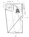
- FIG. 1 represents a side view of a first variant of the device according to the invention when mounted on a box.
- the section transverse of the box (1) on which the device according to the invention is mounted is substantially a rectangular trapezium whose small base (2), corresponding below the box (1), measures, for example, about 15 cm, the large base (3), corresponding to the top of the box (1), measure for example, about 25 cm and the side (4) perpendicular to the small (2) and large (3) base, corresponding to the back of the box (1), for example, around 65cm.
- the length of the box is for example at least equal to 75cm. So the volume available to set up a moving image projection system is relatively reduced.
- the front of the box is open.
- the display device essentially comprises a self-supporting structure (10) mounted on the box (1) and made up of two volumes (11, 12) of determined dimensions so that the structure (10) almost entirely engages in the interior volume of the box (1).
- a first volume (12), located entirely in the upper part of the interior volume of the box (1), is of substantially parallelepiped shape.
- This first volume (12) comprises means for creating an image (described later) and means (110, 112, 114) of projecting this image onto a screen (121) contained in the second volume (12).
- These means of creation of an image and these means (110, 112, 114) of projection of this image are contained in a box (30) made for example of folded sheets and / or welded.
- the longitudinal axis of the box (33) is parallel to both below (3) and at the rear (4) of the box.
- the box (33) is made integral with the second volume (12) by means of at least one tab (31, 32) of attachment, described later.
- Means of projecting the image include in particular a first mirror (110) forming a determined angle with the rear (4) of the box (1) to direct in the horizontal plane and orthogonally, the light rays, symbolized by the lines (R) broken in dotted lines, coming from the image creation means, on a second mirror (112).
- This second mirror (112) is located outside the box (30) and forms a determined angle with a first wall (33) of the box, located most close to the front of the box (1), to deflect the light rays backwards and on a third mirror (123) included in the second volume (12). So the optical path between the first (110) and the third (123) mirrors is included in the same plane, perpendicular to the screen (121) and above (3) of the box (1).
- This particular arrangement makes it possible to reduce the space necessary for the installation of the device in the box (1).
- the angle between the second (112) and the third (123) mirror is low.
- the image projection means also include a objective (114) mounted in the box (30) and located between the first (110) and second (112) mirrors, for example on a vertical support (1141).
- the objective (114) is a short focal length objective for obtaining a large and sufficiently clear image on the screen (121) of the second volume (12).
- the box (30) comprises a hole, for example of rectangular shape in the first wall (33) of the box (30) located closest to the front of the caisson.
- the shape of the second volume (10) is substantially a pyramid with square base, the base of which constitutes the screen (121) of the device.
- the screen (121) is parallel to the front face of the box (1), however it is possible to provide for the screen (121) to make a determined angle with the horizontal.
- the screen (121) is, for example frosted and measured, by example about 80cm in length, and 60cm in width.
- the screen (121) can also have a Fresnel lens effect to enhance and make more uniform its brightness and improve the quality of the projected image.
- the side upper (127) of the pyramid, forming the second volume (12) comprises a horizontal portion (1271), located towards the rear of the box (1), on which is mounted the box (33) of the first volume (11).
- this portion also forms the bottom of the box (30).
- the upper side (127) of the pyramid forming the second volume (12) includes a bore (124) of appropriate dimensions.
- the third mirror (123) is mounted on the lower side (128) of the pyramid forming the second volume (12).
- the value of the angle formed by the third mirror (123) and the screen (123) is determined so that the final image formed on the screen (121) is neither distorted, nor truncated compared to the initial image and that substantially all the screen surface (121) is used to project the image.
- the first volume includes at least a fixing lug (31, 32) allowing its mounting on the second volume (12).
- the box (30) comprises two fixing lugs (31, 32).
- a first tab (31) is located on the lower part of the first wall (33) of the box (30), located most close to the front of the box (1). This tab is attached to the side upper (127) of the pyramid, for example by welding, screwing, gluing, or any other method of attachment.
- the second leg (32) is actually an extension down a second wall of the box (30) located closest to the bottom (4) of the box (1).
- the side (128) of the pyramid bearing the third mirror (123) is parallel to the second tab (32) to allow a securing of said tab (32) with the second volume (12), for example by welding, screwing, gluing or any other means of fixing.
- the dimensions of the pyramid forming the second volume (12) are such that the screen (121) is located at a determined maximum distance from the front face of the box (1). This distance is between 10 and 15 cm.
- the self-supporting structure (10) of the device is mounted on the box by means (125, 126) of fixing located in the part upper and lower of the second (12) volume at the face corresponding to the base of the pyramid forming the second volume (12).
- These fixing means (125, 126) are determined according to the elements available on the box (1). For example, if the box has hooks (5a), the means for fixing the self-supporting structure include additional hooks (not shown), for mounting and support of the self-supporting structure (10).
- the fixing means then consist of lugs (125, 126) which during assembly are adjusted parallel to the edges (5b) of the box (1).
- the mounting of these legs (125, 126) is for example then completed by screw / nut systems which pass through each leg at the same time (125, 126) of the self-supporting structure (10) and the corresponding flanges (5b) of the box (1).
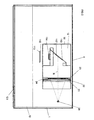
- FIG. 2 represents a top view of the first variant of the device according to the invention.
- the means (20, 21, 22, 23, 24) for creating an image include a source of light (20), preferably of the daylight type, means (21, 22) for homogenize the lighting of an image generation device (23).
- These means for homogenizing the lighting comprise a system (21) of condensers and a catathermic filter (22).
- the generation device of images includes for example a matrix liquid crystal screen (23) active type LCD or TFT and preferably a polarizer (24).
- the system condenser comprises, for example, at least one Fresnel lens.
- the dimensions of the liquid crystal screen (23) are for example about 9 cm 13cm wide and 13cm long.
- the liquid crystal screen (23) allows, by through a computer system (not shown) of known type, view an image or animation. It is within the reach of the skilled person to replace the liquid crystal screen (23) and the polarizer (24) with another equivalent image generation device.
- the optical axis means (20, 21, 22, 23, 24) for creating the image is substantially parallel both to the rear (4) and above (3) of the box.
- the Rays source light (20) then project this image on the first (110) mirror.
- This first mirror is mounted on a second support (117) integral with the bottom of the box (30), to form a determined angle with the wall of the box (30) closest to the bottom (4) of the box. This angle is determined so that the first mirror (110) deflects the light rays towards the second mirror (112) in passing through the objective (114).
- FIG. 3 represents a side view of a second variant of the device according to the invention when mounted on a box.
- the geometry of the box remains unchanged.
- the constitution of the means (210, 212, 214, 223) of image projection and means (20 to 24) does not change.
- the arrangement of the different means vis-à-vis each other is changed.
- the source (not shown) is located in the upper part of the self-supporting structure (10) and between the screen (121) and the opening of the box (1).
- the direction of the optical axis of the source is substantially identical to that of of the first variant.
- the optical axis of the means (21 to 24) for creating the image is substantially perpendicular to the screen (121).
- a first mirror (210) is placed between the source (20) and the means (21 to 24) for creating the image and makes a determined angle with the bottom (4) of the box to deflect the beam (R) towards the means (21 to 24) substantially in a horizontal plane.
- a second mirror (212) is placed between the means (21 to 24) for creating the image and the objective (214) and makes a determined angle with the bottom (4) of the box to deflect the beam (R) towards a third mirror (223) by crossing the objective (214).
- the third mirror (223) makes a determined angle with the screen (121) to deflect the light beam (R) towards it and is, for example, shaped trapezoidal.
- the optical path between the first mirror and screen (121) is also included in the same plane perpendicular to the screen (121) and above (3) of the box (1).
- the axis of the objective (214) is included in a substantially vertical plane. This provision particular to reduce the number of reflections downstream of the lens (214), which improves the quality of the image on the screen (212).
- the optical characteristics of the objective (214) are chosen so that the length of the optical path between the means (21 to 24) for creating the image and the first lens (2141) of the objective (214) represents approximately one and a half times the focal length of the lens. This particular feature allows set up the second mirror (212) between the creation means (21 to 24) of the image and the objective (214) in order to reduce the bulk of the device according to the invention while retaining a satisfactory sharpness of the image projected onto the screen (121).
- the objective used in this second variant embodiment is of the type retrofocus (in English "inverted telephoto”). This type of objective is described in a book entitled “Lens design", by Milton Laikin to Marcel editions Dekker, INC, New York.
- the objective (214) according to the invention comprises, from upstream to downstream of the optical path, a group of lenses (2141, 2142, 2143, 2144) converging and a diverging lens (2145).
- the lens group (2141, 2142, 2143, 2144) converge includes 4 lenses.
- the first lens (2141) is a meniscus converging
- the second lens (2142) is divergent biconcave
- the third lens (2143) is biconvex converging
- the fourth lens (2144) is plano-convex convergent.
- the divergent lens (2145) is a divergent meniscus.
- the optical axes of the five lenses (2141, 2142, 2143, 2144, 2145) are combined and correspond to the optical axis of the objective (214).
- the focal length of the lens is between 70 and 85mm and chosen equal to 78mm and the length of the path optics between the means (21 to 24) for creating the image and the first lens (2141) is between 105 and 130mm and chosen to be 116mm.
- the focal length is determined based on the dimensions of the liquid crystal screen (23) and the projection screen (121).
- the glasses used to produce the lens (2141, 2142, 2143, 2144, 2145) of the objective (214) are provided by the SHOTT company.
- the glass chosen to make the first lens (2141) is sold under the reference SK5.
- the glass chosen to make the second lens (2142) is sold under the reference F5.
- the glass chosen to make the third lens (2143) is sold under the reference SF1.
- the glass chosen to achieve the fourth lens (2144) is sold under the reference BK7.
- the glass chosen for making the fifth lens (2145) is sold under the reference SK16.
- all or part of the mirrors (110, 112, 123) used in the device are either plane mirrors or cylindrical mirrors.
- the device according to the invention is a structure monobloc and self-supporting capable of adapting to a volume box reduced, but also without significantly increasing the total volume of the caisson.
- all the elements of the optical system allowing on the one hand to create an image or an animation then to project this image or animation on a screen are mounted so as to avoid any adjustment after installation of the device according to the invention in the box.
- This feature simplifies considerably installing such a system which usually requires a special care for the adjustment of the various elements of the system.
- taking into account the possible dimensions of the screen and the image created by the image generation device it is possible to get through the device according to the invention, an enlargement of the image created at least equal to 6.
- the system according to the invention allows reduce the costs of installing a rear projection system, since according to the invention the device is adaptable to an existing box, and does not require therefore no significant transformations of it.
Landscapes
- Physics & Mathematics (AREA)
- General Physics & Mathematics (AREA)
- Engineering & Computer Science (AREA)
- Theoretical Computer Science (AREA)
- Multimedia (AREA)
- Signal Processing (AREA)
- Projection Apparatus (AREA)
Description
- la figure 1 représente une vue de côté d'une première variante du dispositif selon l'invention lorsqu'il est monté sur un caisson.
- la figure 2 représente une vue de dessus d'une première variante du dispositif selon l'invention.
- la figure 3 représente une vue de côté d'une deuxième variante du dispositif selon l'invention lorsqu'il est monté sur un caisson.
Claims (15)
- Dispositif d'affichage par rétroprojection, comprenant des moyens (20, 21, 22, 23, 24) de création d'une image, des moyens (110, 112, 114, 123, 210, 212, 214, 223) de projection de cette image sur un écran (121) de dimensions déterminées, ces moyens (110, 112, 114, 123, 210, 212, 214, 223) de projection comprenant une pluralité de miroirs (110, 112, 123, 210, 212, 223), caractérisé en ce que les moyens (20, 21, 22, 23, 24) de création de l'image, les moyens (110, 112, 114, 123) de projection sur l'écran et l'écran (121) sont disposés dans une structure (10) auto-porteuse de volume déterminé par le volume d'un caisson (1) sur lequel est montée la structure par l'intermédiaire de moyens de fixation (125, 126), ces moyens de fixation étant indépendants du réglage ou des positions relatives des éléments portés par cette structure (10).
- Dispositif d'affichage par rétroprojection selon la revendication 1, caractérisé en ce que le chemin optique compris entre le premier miroir (110) et l'écran (121) est compris dans un plan perpendiculaire à cet écran (121) et au dessus (3) du caisson.
- Dispositif d'affichage par rétroprojection selon l'une des revendications 1 à 2, caractérisé en ce que les deux derniers miroirs (112, 123) en aval de l'écran (121) sur le chemin optique de projection sont positionnés dans des plans dont l'intersection avec le plan de l'écran forment deux droites parallèles entre elles.
- Dispositif d'affichage par rétroprojection selon l'une des revendications 1 à 3, caractérisé en ce que les moyens (20, 21, 22, 23, 24) de création d'une image et les moyens (110, 112, 114, 123) de projection de cette image comprennent d'amont en aval, une source lumineuse (20), des moyens (21, 22) d'éclairage homogène d'un dispositif (23) de génération d'images, l'axe optique de la source étant parallèle la fois au plan correspondant au dessus (3) du caisson (1), et au plan correspondant à l'arrière (4) du caisson (1), les moyens (110, 112, 123, 114) de projection de l'image comprennent, un objectif (114) à courte focale, et au moins trois miroirs (110, 112, 123), dont un premier miroir (110) est disposé entre les moyens (20, 21, 22, 23, 24) de création d'image et l'objectif (114) pour dévier, orthogonalement et dans le plan horizontal, les rayons lumineux sur un deuxième miroir (112) disposé en aval de l'objectif (114) et à une distance déterminée de celui-ci, ce deuxième miroir (112) déviant les rayons lumineux vers l'arrière (4) du caisson (1) sur un troisième miroir (123) qui dévie les rayons lumineux vers l'écran (121), l'axe optique de l'objectif (114) étant contenu dans un plan horizontal et le chemin optique compris entre le premier miroir (110) et l'écran (121) étant contenu dans un même plan perpendiculaire à l'écran (121) et au dessus (3) du caisson (1).
- Dispositif d'affichage par rétroprojection selon la revendication 1, caractérisé en ce que les moyens (20, 21, 22, 23, 24) de création d'une image et les moyens (210, 212, 214, 223) de projection de cette image comprennent d'amont en aval, une source lumineuse (20), des moyens (21, 22) d'éclairage homogène d'un dispositif (23) de génération d'images, l'axe optique de la source étant contenu dans un plan parallèle, à la fois au plan correspondant au dessus (3) du caisson (1), et au plan correspondant à l'arrière (4) du caisson (1), les moyens (210, 212, 214, 223) de projection de l'image comprennent un objectif (214) de type rétrofocus et au moins trois miroirs (210, 212, 223), dont un premier miroir (210) est disposé entre la source et les moyens (20, 21, 22, 23, 24) de création d'image pour dévier, orthogonalement et dans le plan horizontal, les rayons lumineux sur un deuxième miroir (212) disposé en aval des moyens (20, 21, 22, 23, 24) de création d'image, ce deuxième miroir (212) déviant les rayons lumineux dans un plan sensiblement vertical, au travers le l'objectif (214) sur un troisième miroir (223) qui dévie les rayons lumineux vers l'écran (121), l'axe optique de l'objectif étant contenu dans un plan vertical et le chemin optique compris entre le premier miroir (210) et l'écran étant contenu dans un même plan, perpendiculaire à l'écran (121) et au-dessus (3) du caisson (1).
- Dispositif d'affichage par rétroprojection selon la revendication 4 ou 5, caractérisé en ce que le dispositif (23, 24) de génération d'images comprend un écran (23) à cristaux liquides à matrice active.
- Dispositif d'affichage par rétroprojection selon la revendication 4, caractérisé en ce que l'objectif est de type rétrofocus comprenant un groupe convergent de quatre lentilles (2141, 2142, 2143, 2143) et une cinquième lentille (2145) divergente, les axes optiques des cinq lentilles (2141, 2142, 2143, 2144, 2145) étant confondus et la distance focale de l'objectif étant déterminée pour que la longueur du chemin optique entre la première lentille (2141) et le dispositif de génération (23, 24) d'image soit de l'ordre de 1,5 fois la distance focale.
- Dispositif d'affichage par rétroprojection selon l'une des revendications 1 à 7, caractérisé en ce que les moyens (21 à 24) de création de l'image comprennent un système (21) de condenseur des faisceaux lumineux comprenant une lentille de Fresnel.
- Dispositif d'affichage par rétroprojection selon l'une des revendications 1 à 8, caractérisé en ce que les dimensions de l'image créée par le dispositif (23) de génération de l'image sont comprises entre 9cm et 10cm de large et 13cm et 15cm de longueur.
- Dispositif d'affichage par rétroprojection selon l'une des revendications 1 à 9, caractérisé en ce que le caisson (1) sur lequel est montée la structure (10) auto-porteuse est, soit une structure existante, soit une structure spécialement aménagée pour le dispositif selon l'invention.
- Dispositif d'affichage par rétroprojection selon l'une des revendications 1 à 10, caractérisé en ce que le rapport d'agrandissement de l'image générée par rapport à l'image projetée est d'au moins 6.
- Dispositif d'affichage par rétroprojection selon l'une des revendications 1 à 11, caractérisé en ce que la surface de l'écran est dépolie et ses dimensions sont sensiblement de 80 cm de longueur et 60 cm de largeur.
- Dispositif d'affichage par rétroprojection selon l'une des revendications 1 à 12, caractérisé en ce que l'écran est situé à une distance maximale de la face avant du caisson comprise entre 10 et 25 cm.
- Dispositif d'affichage par rétroprojection selon l'une des revendications 1 à 13, caractérisé en ce que la forme de chaque miroir est, soit plane, soit cylindrique.
- Dispositif d'affichage par rétroprojection selon l'une des revendications 1 à 14, caractérisé en ce que le volume du caisson (1) est sensiblement un parallélépipède à base trapèze rectangle, les dimensions du trapèze rectangle étant comprises, pour la petite base (2) entre 10 et 20 cm, pour la grande base (3) entre 20 et 30cm, et pour le côté (4) perpendiculaire à la petite (2) et grande base (3) entre 60 et 70cm, la longueur du caisson (1) étant égale à au moins 75 cm.
Applications Claiming Priority (3)
| Application Number | Priority Date | Filing Date | Title |
|---|---|---|---|
| FR9809298A FR2781594B1 (fr) | 1998-07-21 | 1998-07-21 | Dispositif d'affichage par retroprojection |
| FR9809298 | 1998-07-21 | ||
| PCT/FR1999/001788 WO2000005879A1 (fr) | 1998-07-21 | 1999-07-21 | Dispositif d'affichage par retroprojection |
Publications (2)
| Publication Number | Publication Date |
|---|---|
| EP1097573A1 EP1097573A1 (fr) | 2001-05-09 |
| EP1097573B1 true EP1097573B1 (fr) | 2003-03-12 |
Family
ID=9528848
Family Applications (1)
| Application Number | Title | Priority Date | Filing Date |
|---|---|---|---|
| EP99932935A Expired - Lifetime EP1097573B1 (fr) | 1998-07-21 | 1999-07-21 | Dispositif d'affichage par retroprojection |
Country Status (5)
| Country | Link |
|---|---|
| EP (1) | EP1097573B1 (fr) |
| AU (1) | AU4914599A (fr) |
| DE (1) | DE69905896D1 (fr) |
| FR (1) | FR2781594B1 (fr) |
| WO (1) | WO2000005879A1 (fr) |
Families Citing this family (1)
| Publication number | Priority date | Publication date | Assignee | Title |
|---|---|---|---|---|
| WO2005006074A1 (fr) * | 2003-07-08 | 2005-01-20 | Sell Business Solutions, S.L. | Retroprojecteur |
Family Cites Families (6)
| Publication number | Priority date | Publication date | Assignee | Title |
|---|---|---|---|---|
| US3728801A (en) * | 1971-11-08 | 1973-04-24 | R Beckman | Audio-visual teaching unit |
| US4875064A (en) * | 1986-08-06 | 1989-10-17 | Casio Computer Co., Ltd. | Projector apparatus with mirror means |
| US5580146A (en) * | 1992-11-20 | 1996-12-03 | Projectavision, Inc. | Rear screen video display system |
| US5491585A (en) * | 1992-11-20 | 1996-02-13 | Projectavision, Inc. | Portable rear screen television cabinet |
| WO1997001127A2 (fr) * | 1995-06-21 | 1997-01-09 | Smartlight Ltd. | Appareil de retroprojection de transparents |
| US5741057A (en) * | 1996-04-22 | 1998-04-21 | Goldberg; Gerald K. | Device for displaying a projected image |
-
1998
- 1998-07-21 FR FR9809298A patent/FR2781594B1/fr not_active Expired - Fee Related
-
1999
- 1999-07-21 WO PCT/FR1999/001788 patent/WO2000005879A1/fr not_active Ceased
- 1999-07-21 EP EP99932935A patent/EP1097573B1/fr not_active Expired - Lifetime
- 1999-07-21 AU AU49145/99A patent/AU4914599A/en not_active Abandoned
- 1999-07-21 DE DE69905896T patent/DE69905896D1/de not_active Expired - Lifetime
Also Published As
| Publication number | Publication date |
|---|---|
| WO2000005879A1 (fr) | 2000-02-03 |
| EP1097573A1 (fr) | 2001-05-09 |
| DE69905896D1 (de) | 2003-04-17 |
| AU4914599A (en) | 2000-02-14 |
| FR2781594B1 (fr) | 2002-10-25 |
| FR2781594A1 (fr) | 2000-01-28 |
Similar Documents
| Publication | Publication Date | Title |
|---|---|---|
| EP3470728B1 (fr) | Module lumineux pour vehicule automobile | |
| EP0084998B1 (fr) | Appareil optique et procédé pour l'enregistrement ou la visualisation instantanée d'images agrandies et stéréoscopiques d'objets | |
| WO1998020390A1 (fr) | Dispositif de visualisation et ecran plat de television utilisant ce dispositif | |
| EP1817631A1 (fr) | Systeme de projection a repli pour projecteur frontal ou retroprojecteur | |
| EP0737870B1 (fr) | Système de projection comportant un réflecteur et une lentille de champ à surface libre | |
| CA2043622A1 (fr) | Dispositif de visualisation grand angle pour simulateur de faible encombrement | |
| EP1127288A1 (fr) | Dispositif optique pour viseur de casque comportant un miroir diffractif | |
| WO1996002112A1 (fr) | Dispositif de visualisation en couleurs | |
| EP1745329A1 (fr) | Module de projection et projecteur l'incorporant | |
| FR3077394A1 (fr) | Lentille de projection et appareil d’affichage par projection l’utilisant | |
| FR2787591A1 (fr) | Appareil de projection a laser donnant une image de grandes dimensions | |
| FR2895526A1 (fr) | Systeme de retro-eclairage pour panneau d'affichage a cristal liquide et dispositif d'affichage correspondant | |
| EP1097573A1 (fr) | Dispositif d'affichage par retroprojection | |
| EP0738077B1 (fr) | Téléviseur ou moniteur vidéo compact du type à rétroprojection | |
| EP2106667B1 (fr) | Procede d'affichage d'images par projection, a deux etages de modulation, dont l'un par modulation d'ouverture | |
| FR2836238A1 (fr) | Procede pour transferer une image numerique en vue de sa restitution visuelle, et dispositif pour la mise en oeuvre de ce procede | |
| EP1405138B1 (fr) | Ecran de retroprojection | |
| JP2004530939A (ja) | 表示装置 | |
| US20070085980A1 (en) | Projection assembly | |
| FR2892588A1 (fr) | Camera de surveillance generique anti-eblouissement | |
| WO2002059687A1 (fr) | Systeme de projection ou de visualisation d'image | |
| FR2948172A3 (fr) | Paroi lumineuse | |
| FR2607301A1 (fr) | Dispositif d'affichage modulaire a cristaux liquides | |
| EP1156672A1 (fr) | Dispositif de calibration et caméra infra-rouge comportant un tel dispositif | |
| WO2025133476A1 (fr) | Dispositif d'imagerie a forte distorsion geometrique |
Legal Events
| Date | Code | Title | Description |
|---|---|---|---|
| PUAI | Public reference made under article 153(3) epc to a published international application that has entered the european phase |
Free format text: ORIGINAL CODE: 0009012 |
|
| 17P | Request for examination filed |
Effective date: 20010111 |
|
| AK | Designated contracting states |
Kind code of ref document: A1 Designated state(s): AT BE CH CY DE DK ES FI FR GB GR IE IT LI LU MC NL PT SE |
|
| 17Q | First examination report despatched |
Effective date: 20010518 |
|
| GRAG | Despatch of communication of intention to grant |
Free format text: ORIGINAL CODE: EPIDOS AGRA |
|
| GRAG | Despatch of communication of intention to grant |
Free format text: ORIGINAL CODE: EPIDOS AGRA |
|
| GRAH | Despatch of communication of intention to grant a patent |
Free format text: ORIGINAL CODE: EPIDOS IGRA |
|
| GRAH | Despatch of communication of intention to grant a patent |
Free format text: ORIGINAL CODE: EPIDOS IGRA |
|
| GRAH | Despatch of communication of intention to grant a patent |
Free format text: ORIGINAL CODE: EPIDOS IGRA |
|
| GRAA | (expected) grant |
Free format text: ORIGINAL CODE: 0009210 |
|
| AK | Designated contracting states |
Designated state(s): CH DE ES FR GB IT LI |
|
| PG25 | Lapsed in a contracting state [announced via postgrant information from national office to epo] |
Ref country code: IT Free format text: LAPSE BECAUSE OF FAILURE TO SUBMIT A TRANSLATION OF THE DESCRIPTION OR TO PAY THE FEE WITHIN THE PRESCRIBED TIME-LIMIT;WARNING: LAPSES OF ITALIAN PATENTS WITH EFFECTIVE DATE BEFORE 2007 MAY HAVE OCCURRED AT ANY TIME BEFORE 2007. THE CORRECT EFFECTIVE DATE MAY BE DIFFERENT FROM THE ONE RECORDED. Effective date: 20030312 Ref country code: GB Free format text: LAPSE BECAUSE OF FAILURE TO SUBMIT A TRANSLATION OF THE DESCRIPTION OR TO PAY THE FEE WITHIN THE PRESCRIBED TIME-LIMIT Effective date: 20030312 |
|
| REG | Reference to a national code |
Ref country code: GB Ref legal event code: FG4D Free format text: NOT ENGLISH |
|
| REG | Reference to a national code |
Ref country code: CH Ref legal event code: EP |
|
| REG | Reference to a national code |
Ref country code: IE Ref legal event code: FG4D Free format text: FRENCH |
|
| REF | Corresponds to: |
Ref document number: 69905896 Country of ref document: DE Date of ref document: 20030417 Kind code of ref document: P |
|
| PG25 | Lapsed in a contracting state [announced via postgrant information from national office to epo] |
Ref country code: DE Free format text: LAPSE BECAUSE OF FAILURE TO SUBMIT A TRANSLATION OF THE DESCRIPTION OR TO PAY THE FEE WITHIN THE PRESCRIBED TIME-LIMIT Effective date: 20030613 |
|
| PG25 | Lapsed in a contracting state [announced via postgrant information from national office to epo] |
Ref country code: LI Free format text: LAPSE BECAUSE OF NON-PAYMENT OF DUE FEES Effective date: 20030731 Ref country code: CH Free format text: LAPSE BECAUSE OF NON-PAYMENT OF DUE FEES Effective date: 20030731 |
|
| GBV | Gb: ep patent (uk) treated as always having been void in accordance with gb section 77(7)/1977 [no translation filed] |
Effective date: 20030312 |
|
| PG25 | Lapsed in a contracting state [announced via postgrant information from national office to epo] |
Ref country code: ES Free format text: LAPSE BECAUSE OF FAILURE TO SUBMIT A TRANSLATION OF THE DESCRIPTION OR TO PAY THE FEE WITHIN THE PRESCRIBED TIME-LIMIT Effective date: 20030930 |
|
| REG | Reference to a national code |
Ref country code: IE Ref legal event code: FD4D Ref document number: 1097573E Country of ref document: IE |
|
| PLBE | No opposition filed within time limit |
Free format text: ORIGINAL CODE: 0009261 |
|
| STAA | Information on the status of an ep patent application or granted ep patent |
Free format text: STATUS: NO OPPOSITION FILED WITHIN TIME LIMIT |
|
| 26N | No opposition filed |
Effective date: 20031215 |
|
| REG | Reference to a national code |
Ref country code: CH Ref legal event code: PL |
|
| PGFP | Annual fee paid to national office [announced via postgrant information from national office to epo] |
Ref country code: FR Payment date: 20100813 Year of fee payment: 12 |
|
| REG | Reference to a national code |
Ref country code: FR Ref legal event code: TP Owner name: MERIM SERVICES, FR Effective date: 20111116 |
|
| REG | Reference to a national code |
Ref country code: FR Ref legal event code: GC Effective date: 20120312 |
|
| REG | Reference to a national code |
Ref country code: FR Ref legal event code: ST Effective date: 20120330 |
|
| PG25 | Lapsed in a contracting state [announced via postgrant information from national office to epo] |
Ref country code: FR Free format text: LAPSE BECAUSE OF NON-PAYMENT OF DUE FEES Effective date: 20110801 |