EP1097660B1 - Schiebe- oder Absperrungseinrichting zum Einstellen oder Verändern einer Position von Stühlen oder Teilen davon - Google Patents
Schiebe- oder Absperrungseinrichting zum Einstellen oder Verändern einer Position von Stühlen oder Teilen davon Download PDFInfo
- Publication number
- EP1097660B1 EP1097660B1 EP99830689A EP99830689A EP1097660B1 EP 1097660 B1 EP1097660 B1 EP 1097660B1 EP 99830689 A EP99830689 A EP 99830689A EP 99830689 A EP99830689 A EP 99830689A EP 1097660 B1 EP1097660 B1 EP 1097660B1
- Authority
- EP
- European Patent Office
- Prior art keywords
- plates
- rod
- blocking
- blocking position
- runner
- Prior art date
- Legal status (The legal status is an assumption and is not a legal conclusion. Google has not performed a legal analysis and makes no representation as to the accuracy of the status listed.)
- Expired - Lifetime
Links
Images

Classifications
-
- A—HUMAN NECESSITIES
- A47—FURNITURE; DOMESTIC ARTICLES OR APPLIANCES; COFFEE MILLS; SPICE MILLS; SUCTION CLEANERS IN GENERAL
- A47C—CHAIRS; SOFAS; BEDS
- A47C1/00—Chairs adapted for special purposes
- A47C1/02—Reclining or easy chairs
- A47C1/022—Reclining or easy chairs having independently-adjustable supporting parts
- A47C1/024—Reclining or easy chairs having independently-adjustable supporting parts the parts, being the back-rest, or the back-rest and seat unit, having adjustable inclination
- A47C1/027—Reclining or easy chairs having independently-adjustable supporting parts the parts, being the back-rest, or the back-rest and seat unit, having adjustable inclination by means of clamps or friction locking members
-
- A—HUMAN NECESSITIES
- A47—FURNITURE; DOMESTIC ARTICLES OR APPLIANCES; COFFEE MILLS; SPICE MILLS; SUCTION CLEANERS IN GENERAL
- A47C—CHAIRS; SOFAS; BEDS
- A47C1/00—Chairs adapted for special purposes
- A47C1/02—Reclining or easy chairs
- A47C1/031—Reclining or easy chairs having coupled concurrently adjustable supporting parts
- A47C1/032—Reclining or easy chairs having coupled concurrently adjustable supporting parts the parts being movably-coupled seat and back-rest
- A47C1/03205—Reclining or easy chairs having coupled concurrently adjustable supporting parts the parts being movably-coupled seat and back-rest having adjustable and lockable inclination
- A47C1/0325—Reclining or easy chairs having coupled concurrently adjustable supporting parts the parts being movably-coupled seat and back-rest having adjustable and lockable inclination by means of clamps or friction locking members
-
- A—HUMAN NECESSITIES
- A47—FURNITURE; DOMESTIC ARTICLES OR APPLIANCES; COFFEE MILLS; SPICE MILLS; SUCTION CLEANERS IN GENERAL
- A47C—CHAIRS; SOFAS; BEDS
- A47C1/00—Chairs adapted for special purposes
- A47C1/02—Reclining or easy chairs
- A47C1/031—Reclining or easy chairs having coupled concurrently adjustable supporting parts
- A47C1/032—Reclining or easy chairs having coupled concurrently adjustable supporting parts the parts being movably-coupled seat and back-rest
- A47C1/03255—Reclining or easy chairs having coupled concurrently adjustable supporting parts the parts being movably-coupled seat and back-rest with a central column, e.g. rocking office chairs
Definitions
- This invention concerns, in general, seating structures like office chairs and armchairs, car seats, or any others requiring regulation and, in particular, concerns a device for choosing and stabilising the user positions of such chairs and/or their parts.
- Such a device allows a gradual regulation, that is, not in steps, of the angle between the two elements connected by a joint, such as the seat and back of a chair, thanks to the use, as a positioning element, of a smooth shaft and, as a blocking element, of a plate that acts upon said shaft.
- These devices generally comprise a sliding rod and at least a pair of gripping or frictional elements designed to oscillate between an unlocked position wherein are disposed substantially perpendicular to the rod to permit the free movement of the same, and a sloped locked position wherein are in frictional engagement with the rod for preventing any movement of the same, at least in one direction.
- the aim, however, of the present invention is to improve such a sliding blocking device and make it suitable and specifically applicable to oscillating and synchronised chairs, with the dual function of being able to vary the inclination of the seat and back freely at will, with no obligatory positions and, at the same time, preventing the back from moving suddenly and violently towards the chair occupant, hitting the person's back, every time it is unblocked to adjust the position.
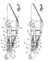
- the proposed blocking device 10 is applied to an oscillating group for office chairs, which includes: a fixed body 11, to be applied to the top of an extendable upright support - not represented - and intended to carry the seat; an oscillating support 12, hinged to said body 11 with an oscillating cross shaft 13 and intended to carry a back with an adjustable angle to the seat; and an adjustable spring between the fixed body 11 and the oscillating support 12.
- the blocking device 10 includes a cylindrical rod 15 and two gripping plates 16,17.
- the rod 15 is connected, at the back, to the oscillating support 12 by means of a cross pin 18, parallel to the oscillating shaft 13 and passing through holes 19, located in the fixed body 11.
- the rod 15 extends from the back to the front under the seat, inside the body 11.
- Said rod 15 has the front end held in a block 20, fixed to the body 11, and may have a smooth surface or, preferably, a knurled or rough one.
- the two gripping plates 16,17 are positioned at right angles to the rod 15, each with a foot 16',17', forming a fulcrum with the body 11. Both the plates 16,17 have a cross-hole 16",17" and the rod 15 passes through said holes.
- the plates 16,17 can be moved between an orthogonal non-blocking position and a blocking position sloped with respect to the rod 15. In the orthogonal non-blocking position, the axis of the holes in the plates coincides with the rod axis, so that the latter may pass through said holes, relatively to the plates. In the sloped blocking position, the edge of the hole on each plate interacts with the external surface of the rod, with a gripping action that prevents the axial movements of the rod itself.
- the plates 16,17 have a fulcrum for oscillating between the orthogonal and sloped positions, the first in the opposite direction to the second and in such a way that they both act upon, and block, the rod - one against the axial movements of the rod in one direction and the other against the movements in the other direction.
- the plates 16,17 are normally kept in their sloped blocking position by an elastic system 22 and can be moved into their non-blocking position by means of a command lever 23 with the help of a runner 24 that slides relatively to the rod 15.
- Said lever is designed for a dual function: to control the height regulation of the support upright of the chair; to command the blocking/un-blocking device by means of the runner 24.
- This runner 24 is situated in a position between the pin 18 of the rod 15 and the plates 16,17, and can move from a backward blocking position, near said pin, to a forward non-blocking position, near said plate.
- the command lever 23 passes, from the outside, through a hole 25 made in one side of the fixed body 11, extending through a ring hole 26 set in a dividing wall 27 fixed to said body 11 and with its end using the runner 24.
- the lever 23 has an arm 28, designed to control the height regulation of the support upright and forming, with one of its parts, a shoulder 28' designed to interact with a blocking tooth 29 when the lever is in the non-blocking position of the device 10.
- the command lever 23 can move forward axially, towards the runner 24, according to the arrow A (Fig. 1), and backwards according to arrow B, as well as make angular movements, according to arrow C, with its fulcrum in the hole 25 in the side of the body 11, and rotational movements according to arrow D.
- the axial and angular movements are intended to control the runner, while the rotation is intended to control the support upright.
- the elastic system 22 which keeps the gripping plates in the blocking position includes a first spring 30, placed between the two plates 16,17, on a small guiding rod 31.
- This small rod 31 is fastened at one end to the first plate 16, the one which is furthest from the runner, and passes freely through corresponding holes made in the other plate 17 and in the runner 24.
- the spring 30 is mounted with a certain tension in such a way as to keep the plates 16,17 apart and in a position to interact with the rod 15.
- the system 22 includes, furthermore, a second spring 32, positioned in the runner 24 and in line with a pusher 33 which extends forwards across the plates without impediment until it comes to rest against a part of the horizontally pivoted lever 34, which has its fulcrum in 34' at the guiding block 20 of the rod 15, with its other side partly resting against the small rod 31 fixed to the plate 16 and carrying the first spring 30.
- the first spring 30 keeps the plates 16,17 apart, at an angle with respect to the rod 15, and, therefore, in the position to interact with the rod and to block the back support 12, with respect to the seat bearing body.
Landscapes
- Health & Medical Sciences (AREA)
- Dentistry (AREA)
- General Health & Medical Sciences (AREA)
- Chairs For Special Purposes, Such As Reclining Chairs (AREA)
- Sliding Valves (AREA)
- Chairs Characterized By Structure (AREA)
- Chair Legs, Seat Parts, And Backrests (AREA)
Claims (4)
- Stuhl- oder Sitzstruktur, wie Bürosessel, Armstuhle, Autositze oder ähnliche Vorrichtungen, umfassend:einen stationären Körper (11), der an einem Support bzw. einer Stutze bzw. Unterstützung aufrecht festgelegt ist und den Sitz trägt,einen oszillierenden Support bzw. Unterstuzung (12), der bzw. die an dem stationären Körper angelenkt bzw. schwenkbar ist und die Rückseite bzw. die Rückenlehne und elastische Mittel zum Verbinden des stationären Körpers und der oszillierenden Stütze so tragt, um den Oszillationen bzw. Schwingungen des Letzteren entgegen zu wirken,eine Vorrichtung (10) zum Blockieren des Schwingens der oszillierenden Stütze , die die Rückenlehne in jeglicher Position trägt, in bezug auf den stationären Körper, der den Sitz trägt,eine zylindrische Stange (15), die mit der oszillierenden Stutze (12) verbunden ist, die sich nach vorwärts unter dem stationären Körper (11) erstreckt und durch einen Führungsblock (20) gleitet,zwei greifende bzw. Greifplatten (13, 17), die geneigt zu der zylindrischen Stange (15)angeordnet sind, jede mit einem Fuß, der auf dem stationären Kopper rotiert, und mit einem Loch, um es der Stange zu ermöglichen durchzutreten, und wobeisich die Platten (16, 17) von einer orthogonalen, nicht blockierenden Position, wo sie senkrecht zu der zylindrischen Stange sind und die Achse ihrer quer verlaufenden Löcher mit der Achse der Stange für das Gleiten der Letzteren zusammenfällt , und einer geneigten blockierenden Position bewegen Können, wo die Kante der quer verlaufenden Löcher mit der externen Oberfläche der Stange zusammenwirkt, die sie axial blockiert;die Platten, wenn sie in der geneigten blockierenden Position sind, in entgegengesetzten Richtungen auf eine derartige Weise abgewinkelt sind, daß eine Platte auf die Stange in einer Richtung wirken und diese blockieren kann und die andere Platte dasselbe in der anderen Richtung tun kann;zwischen der zylindrischen Stange (15) und den Greifplatten (16, 17) einige Mittel zum Bewegen der Platten auf Befehl zu der orthogonalen, nicht blockierenden Position vorhanden sind;die Platten (16, 17) normalerweise in der geneigten blockierenden Position durch eine Feder (30) gehalten sind, die zwischen den Platten selbst angeordnet ist und auf einer kleinen führenden bzw. Führungsstange (31)festgelegt ist, die auf einer Platte festgelegt ist und in bezug auf die andere gleitet, dadurch gekennzeichnet, daß;die Mittel zum Bewegen der Platten (16, 17) in die orthogonale nicht-blockierende Position einen Läufer (24) beinhalten, welcher sich in bezug auf die zylindrische Stange (15) von einer rückwärtigen Position nahe dem Gelenk der Stange zu einer vorderen Position nahe den Platten bewegen kann, eine Feder (32), die in dem Läufer in einer Linie mit einem Drücker bzw. einer Schiebeeinrichtung (33) festgelegt ist, welche(r) sich durch die Platten soweit wie ein horizontal geschwenkter Hebel (34) erstreckt, welcher seinen Stützpunkt an dem Führungsblock der zylindrischen Stange aufweist und welcher gegen eine Platte benachbart dem Block in einer derartigen Weise aufruht, das die Bewegung des Läufers von der rückwärtigen zu der vorderen Position zuerst der Bewegung von einer der Platten und zweitens der Bewegung von den anderen Platten in die nicht blockierende Position entspricht.
- Vorrichtung nach Anspruch 1, in welcher die zylindrische Stange (15) mit der oszillierenden Stütze (12) mittels eines Kreuzzapfens (18) verbunden ist, der durch Ringlocher (19) hindurchtritt, die in dem stationären Körper angeordnet sind.
- Vorrichtung nach Anspruch 1 oder 2, in welcher der Läufer und winkeligen Bewegungen an einem Schwenk- bzw. Stützpunkt fähig ist, wobei der Hebel weiterhin fähig ist, so zu drehen bzw. zu schwenken, daß er die Mittel zum Regulieren der Höhe der Stütze oberhalb des Stuhls steuern bzw, regeln kann.
- Vorrichtung nach einem der Ansprüche 1 bis 3, wobei die zylindrische Stange (15) eine glatte oder rauhe Oberfläche aufweist.
Priority Applications (3)
| Application Number | Priority Date | Filing Date | Title |
|---|---|---|---|
| EP99830689A EP1097660B1 (de) | 1999-11-02 | 1999-11-02 | Schiebe- oder Absperrungseinrichting zum Einstellen oder Verändern einer Position von Stühlen oder Teilen davon |
| DE69926375T DE69926375D1 (de) | 1999-11-02 | 1999-11-02 | Schiebe- oder Absperrungseinrichting zum Einstellen oder Verändern einer Position von Stühlen oder Teilen davon |
| AT99830689T ATE300208T1 (de) | 1999-11-02 | 1999-11-02 | Schiebe- oder absperrungseinrichting zum einstellen oder verändern einer position von stühlen oder teilen davon |
Applications Claiming Priority (1)
| Application Number | Priority Date | Filing Date | Title |
|---|---|---|---|
| EP99830689A EP1097660B1 (de) | 1999-11-02 | 1999-11-02 | Schiebe- oder Absperrungseinrichting zum Einstellen oder Verändern einer Position von Stühlen oder Teilen davon |
Publications (2)
| Publication Number | Publication Date |
|---|---|
| EP1097660A1 EP1097660A1 (de) | 2001-05-09 |
| EP1097660B1 true EP1097660B1 (de) | 2005-07-27 |
Family
ID=8243655
Family Applications (1)
| Application Number | Title | Priority Date | Filing Date |
|---|---|---|---|
| EP99830689A Expired - Lifetime EP1097660B1 (de) | 1999-11-02 | 1999-11-02 | Schiebe- oder Absperrungseinrichting zum Einstellen oder Verändern einer Position von Stühlen oder Teilen davon |
Country Status (3)
| Country | Link |
|---|---|
| EP (1) | EP1097660B1 (de) |
| AT (1) | ATE300208T1 (de) |
| DE (1) | DE69926375D1 (de) |
Family Cites Families (6)
| Publication number | Priority date | Publication date | Assignee | Title |
|---|---|---|---|---|
| FR1466417A (fr) * | 1965-12-01 | 1967-01-20 | Publicite Francaise | Dispositif de blocage mécanique et ses applications, en particulier aux sièges réglables |
| US4387926A (en) * | 1981-06-26 | 1983-06-14 | Rockwell International Corporation | Seat positioner |
| US4452098A (en) * | 1982-07-02 | 1984-06-05 | General Engineering & Manufacturing Corp. | Locking and positioning device for reclining seats |
| US4441381A (en) * | 1982-09-30 | 1984-04-10 | General Engineering & Manufacturing Corp. | Locking and positioning apparatus for reclining seats |
| US5105486A (en) * | 1990-06-18 | 1992-04-21 | Joerns Healthcare Inc. | Adjustable bed |
| GB2278772A (en) * | 1993-06-10 | 1994-12-14 | Johnson Controls Adwest | Lever actuated seat recliner |
-
1999
- 1999-11-02 AT AT99830689T patent/ATE300208T1/de not_active IP Right Cessation
- 1999-11-02 EP EP99830689A patent/EP1097660B1/de not_active Expired - Lifetime
- 1999-11-02 DE DE69926375T patent/DE69926375D1/de not_active Expired - Lifetime
Also Published As
| Publication number | Publication date |
|---|---|
| EP1097660A1 (de) | 2001-05-09 |
| ATE300208T1 (de) | 2005-08-15 |
| DE69926375D1 (de) | 2005-09-01 |
Similar Documents
| Publication | Publication Date | Title |
|---|---|---|
| EP0516341A1 (de) | Schaukelmechanismus für Stühle | |
| EP0039576A2 (de) | Einstellvorrichtung für einen Stuhlsitz | |
| EP1527714B1 (de) | Stuhl | |
| JP3663217B2 (ja) | いす | |
| US4763950A (en) | Tilting chair, especially office chair | |
| US7566097B2 (en) | Chair, in particular office chair | |
| US6238000B1 (en) | Mechanism for chair | |
| CN105848525B (zh) | 具有可调整靠背的椅子 | |
| JPH0243481B2 (de) | ||
| NL8703027A (nl) | Kantelregelinrichting voor een bureaustoel. | |
| US7946651B2 (en) | Mechanism for adjusting the inclination of backrests in chairs and arm-chairs, particularly in office chairs | |
| JPH03109009A (ja) | 傾斜可能な椅子の支持装置 | |
| US4858993A (en) | Work chair comprising a swivelling seat shell | |
| US4787673A (en) | Chair support with adjustment device | |
| US5921630A (en) | Height adjustment mechanism for a back rest or an arm rest of a chair | |
| KR100619601B1 (ko) | 틸팅리미트 및 로킹 가능한 의자 | |
| CA2080720A1 (en) | Device for adjusting seat frame and back rest of chair of swivel type | |
| US5388889A (en) | Torque control mechanism for chairs | |
| KR20060113549A (ko) | 리클라이닝 기구 | |
| JPWO2009147869A1 (ja) | 背もたれの傾動可能な椅子 | |
| EP1097660A1 (de) | Schiebe- oder Absperrungseinrichting zum Einstellen oder Verändern einer Position von Stühlen oder Teilen davon | |
| JP2797273B2 (ja) | 背もたれ付き椅子 | |
| JP4754679B2 (ja) | 椅子における背凭れの傾動範囲調節装置 | |
| KR200385119Y1 (ko) | 틸팅가능 의자의 포워딩 장치 | |
| KR102083157B1 (ko) | 의자의 틸트 교번 기구 |
Legal Events
| Date | Code | Title | Description |
|---|---|---|---|
| PUAI | Public reference made under article 153(3) epc to a published international application that has entered the european phase |
Free format text: ORIGINAL CODE: 0009012 |
|
| AK | Designated contracting states |
Kind code of ref document: A1 Designated state(s): AT BE CH CY DE DK ES FI FR GB GR IE IT LI LU MC NL PT SE |
|
| AX | Request for extension of the european patent |
Free format text: AL;LT;LV;MK;RO;SI |
|
| 17P | Request for examination filed |
Effective date: 20010903 |
|
| AKX | Designation fees paid |
Free format text: AT BE CH CY DE DK ES FI FR GB GR IE IT LI LU MC NL PT SE |
|
| AXX | Extension fees paid |
Free format text: AL PAYMENT 20010903;RO PAYMENT 20010903;SI PAYMENT 20010903 |
|
| 17Q | First examination report despatched |
Effective date: 20030424 |
|
| GRAP | Despatch of communication of intention to grant a patent |
Free format text: ORIGINAL CODE: EPIDOSNIGR1 |
|
| GRAS | Grant fee paid |
Free format text: ORIGINAL CODE: EPIDOSNIGR3 |
|
| GRAA | (expected) grant |
Free format text: ORIGINAL CODE: 0009210 |
|
| AK | Designated contracting states |
Kind code of ref document: B1 Designated state(s): AT BE CH CY DE DK ES FI FR GB GR IE IT LI LU MC NL PT SE |
|
| AX | Request for extension of the european patent |
Extension state: AL RO SI |
|
| PG25 | Lapsed in a contracting state [announced via postgrant information from national office to epo] |
Ref country code: NL Free format text: LAPSE BECAUSE OF FAILURE TO SUBMIT A TRANSLATION OF THE DESCRIPTION OR TO PAY THE FEE WITHIN THE PRESCRIBED TIME-LIMIT Effective date: 20050727 Ref country code: LI Free format text: LAPSE BECAUSE OF FAILURE TO SUBMIT A TRANSLATION OF THE DESCRIPTION OR TO PAY THE FEE WITHIN THE PRESCRIBED TIME-LIMIT Effective date: 20050727 Ref country code: FI Free format text: LAPSE BECAUSE OF FAILURE TO SUBMIT A TRANSLATION OF THE DESCRIPTION OR TO PAY THE FEE WITHIN THE PRESCRIBED TIME-LIMIT Effective date: 20050727 Ref country code: CH Free format text: LAPSE BECAUSE OF FAILURE TO SUBMIT A TRANSLATION OF THE DESCRIPTION OR TO PAY THE FEE WITHIN THE PRESCRIBED TIME-LIMIT Effective date: 20050727 Ref country code: BE Free format text: LAPSE BECAUSE OF FAILURE TO SUBMIT A TRANSLATION OF THE DESCRIPTION OR TO PAY THE FEE WITHIN THE PRESCRIBED TIME-LIMIT Effective date: 20050727 Ref country code: AT Free format text: LAPSE BECAUSE OF FAILURE TO SUBMIT A TRANSLATION OF THE DESCRIPTION OR TO PAY THE FEE WITHIN THE PRESCRIBED TIME-LIMIT Effective date: 20050727 |
|
| REG | Reference to a national code |
Ref country code: GB Ref legal event code: FG4D |
|
| REG | Reference to a national code |
Ref country code: CH Ref legal event code: EP |
|
| REG | Reference to a national code |
Ref country code: IE Ref legal event code: FG4D |
|
| REF | Corresponds to: |
Ref document number: 69926375 Country of ref document: DE Date of ref document: 20050901 Kind code of ref document: P |
|
| PG25 | Lapsed in a contracting state [announced via postgrant information from national office to epo] |
Ref country code: SE Free format text: LAPSE BECAUSE OF FAILURE TO SUBMIT A TRANSLATION OF THE DESCRIPTION OR TO PAY THE FEE WITHIN THE PRESCRIBED TIME-LIMIT Effective date: 20051027 Ref country code: GR Free format text: LAPSE BECAUSE OF FAILURE TO SUBMIT A TRANSLATION OF THE DESCRIPTION OR TO PAY THE FEE WITHIN THE PRESCRIBED TIME-LIMIT Effective date: 20051027 Ref country code: DK Free format text: LAPSE BECAUSE OF FAILURE TO SUBMIT A TRANSLATION OF THE DESCRIPTION OR TO PAY THE FEE WITHIN THE PRESCRIBED TIME-LIMIT Effective date: 20051027 |
|
| PG25 | Lapsed in a contracting state [announced via postgrant information from national office to epo] |
Ref country code: DE Free format text: LAPSE BECAUSE OF FAILURE TO SUBMIT A TRANSLATION OF THE DESCRIPTION OR TO PAY THE FEE WITHIN THE PRESCRIBED TIME-LIMIT Effective date: 20051028 |
|
| PG25 | Lapsed in a contracting state [announced via postgrant information from national office to epo] |
Ref country code: IE Free format text: LAPSE BECAUSE OF NON-PAYMENT OF DUE FEES Effective date: 20051102 Ref country code: GB Free format text: LAPSE BECAUSE OF NON-PAYMENT OF DUE FEES Effective date: 20051102 Ref country code: CY Free format text: LAPSE BECAUSE OF FAILURE TO SUBMIT A TRANSLATION OF THE DESCRIPTION OR TO PAY THE FEE WITHIN THE PRESCRIBED TIME-LIMIT Effective date: 20051102 |
|
| PG25 | Lapsed in a contracting state [announced via postgrant information from national office to epo] |
Ref country code: ES Free format text: LAPSE BECAUSE OF FAILURE TO SUBMIT A TRANSLATION OF THE DESCRIPTION OR TO PAY THE FEE WITHIN THE PRESCRIBED TIME-LIMIT Effective date: 20051107 |
|
| PG25 | Lapsed in a contracting state [announced via postgrant information from national office to epo] |
Ref country code: LU Free format text: LAPSE BECAUSE OF NON-PAYMENT OF DUE FEES Effective date: 20051130 |
|
| PG25 | Lapsed in a contracting state [announced via postgrant information from national office to epo] |
Ref country code: PT Free format text: LAPSE BECAUSE OF FAILURE TO SUBMIT A TRANSLATION OF THE DESCRIPTION OR TO PAY THE FEE WITHIN THE PRESCRIBED TIME-LIMIT Effective date: 20051227 |
|
| REG | Reference to a national code |
Ref country code: CH Ref legal event code: PL |
|
| NLV1 | Nl: lapsed or annulled due to failure to fulfill the requirements of art. 29p and 29m of the patents act | ||
| PLBE | No opposition filed within time limit |
Free format text: ORIGINAL CODE: 0009261 |
|
| STAA | Information on the status of an ep patent application or granted ep patent |
Free format text: STATUS: NO OPPOSITION FILED WITHIN TIME LIMIT |
|
| 26N | No opposition filed |
Effective date: 20060428 |
|
| GBPC | Gb: european patent ceased through non-payment of renewal fee |
Effective date: 20051102 |
|
| REG | Reference to a national code |
Ref country code: IE Ref legal event code: MM4A |
|
| EN | Fr: translation not filed | ||
| PG25 | Lapsed in a contracting state [announced via postgrant information from national office to epo] |
Ref country code: FR Free format text: LAPSE BECAUSE OF FAILURE TO SUBMIT A TRANSLATION OF THE DESCRIPTION OR TO PAY THE FEE WITHIN THE PRESCRIBED TIME-LIMIT Effective date: 20060922 |
|
| PG25 | Lapsed in a contracting state [announced via postgrant information from national office to epo] |
Ref country code: FR Free format text: LAPSE BECAUSE OF FAILURE TO SUBMIT A TRANSLATION OF THE DESCRIPTION OR TO PAY THE FEE WITHIN THE PRESCRIBED TIME-LIMIT Effective date: 20051130 |
|
| PG25 | Lapsed in a contracting state [announced via postgrant information from national office to epo] |
Ref country code: FR Free format text: LAPSE BECAUSE OF FAILURE TO SUBMIT A TRANSLATION OF THE DESCRIPTION OR TO PAY THE FEE WITHIN THE PRESCRIBED TIME-LIMIT Effective date: 20050727 |
|
| PGFP | Annual fee paid to national office [announced via postgrant information from national office to epo] |
Ref country code: IT Payment date: 20091127 Year of fee payment: 11 |
|
| PGFP | Annual fee paid to national office [announced via postgrant information from national office to epo] |
Ref country code: MC Payment date: 20101112 Year of fee payment: 12 |
|
| PG25 | Lapsed in a contracting state [announced via postgrant information from national office to epo] |
Ref country code: IT Free format text: LAPSE BECAUSE OF NON-PAYMENT OF DUE FEES Effective date: 20101102 |
|
| PG25 | Lapsed in a contracting state [announced via postgrant information from national office to epo] |
Ref country code: MC Free format text: LAPSE BECAUSE OF NON-PAYMENT OF DUE FEES Effective date: 20111130 |