EP1097665A2 - Mécanisme de transfert de bande pour distributeur de feuilles flexibles - Google Patents
Mécanisme de transfert de bande pour distributeur de feuilles flexibles Download PDFInfo
- Publication number
- EP1097665A2 EP1097665A2 EP00309882A EP00309882A EP1097665A2 EP 1097665 A2 EP1097665 A2 EP 1097665A2 EP 00309882 A EP00309882 A EP 00309882A EP 00309882 A EP00309882 A EP 00309882A EP 1097665 A2 EP1097665 A2 EP 1097665A2
- Authority
- EP
- European Patent Office
- Prior art keywords
- web
- transfer
- arm
- roll
- feed
- Prior art date
- Legal status (The legal status is an assumption and is not a legal conclusion. Google has not performed a legal analysis and makes no representation as to the accuracy of the status listed.)
- Withdrawn
Links
Images


Classifications
-
- A—HUMAN NECESSITIES
- A47—FURNITURE; DOMESTIC ARTICLES OR APPLIANCES; COFFEE MILLS; SPICE MILLS; SUCTION CLEANERS IN GENERAL
- A47K—SANITARY EQUIPMENT; ACCESSORIES THEREFOR, e.g. TOILET ACCESSORIES
- A47K10/00—Body-drying implements; Toilet paper; Holders therefor
- A47K10/24—Towel dispensers; Toilet paper dispensers
- A47K10/32—Dispensers for paper towels or toilet paper
- A47K10/34—Dispensers for paper towels or toilet paper dispensing from a web, e.g. with mechanical dispensing means
- A47K10/36—Dispensers for paper towels or toilet paper dispensing from a web, e.g. with mechanical dispensing means with mechanical dispensing, roll switching or cutting devices
- A47K10/3687—Dispensers for paper towels or toilet paper dispensing from a web, e.g. with mechanical dispensing means with mechanical dispensing, roll switching or cutting devices with one or more reserve rolls
-
- A—HUMAN NECESSITIES
- A47—FURNITURE; DOMESTIC ARTICLES OR APPLIANCES; COFFEE MILLS; SPICE MILLS; SUCTION CLEANERS IN GENERAL
- A47K—SANITARY EQUIPMENT; ACCESSORIES THEREFOR, e.g. TOILET ACCESSORIES
- A47K10/00—Body-drying implements; Toilet paper; Holders therefor
- A47K10/24—Towel dispensers; Toilet paper dispensers
- A47K10/32—Dispensers for paper towels or toilet paper
- A47K10/34—Dispensers for paper towels or toilet paper dispensing from a web, e.g. with mechanical dispensing means
- A47K10/36—Dispensers for paper towels or toilet paper dispensing from a web, e.g. with mechanical dispensing means with mechanical dispensing, roll switching or cutting devices
- A47K10/3631—The cutting devices being driven manually
- A47K10/3643—The cutting devices being driven manually by pulling the paper
-
- A—HUMAN NECESSITIES
- A47—FURNITURE; DOMESTIC ARTICLES OR APPLIANCES; COFFEE MILLS; SPICE MILLS; SUCTION CLEANERS IN GENERAL
- A47K—SANITARY EQUIPMENT; ACCESSORIES THEREFOR, e.g. TOILET ACCESSORIES
- A47K10/00—Body-drying implements; Toilet paper; Holders therefor
- A47K10/24—Towel dispensers; Toilet paper dispensers
- A47K10/32—Dispensers for paper towels or toilet paper
- A47K10/34—Dispensers for paper towels or toilet paper dispensing from a web, e.g. with mechanical dispensing means
- A47K10/36—Dispensers for paper towels or toilet paper dispensing from a web, e.g. with mechanical dispensing means with mechanical dispensing, roll switching or cutting devices
- A47K10/3631—The cutting devices being driven manually
- A47K2010/365—Triggering mechanism for the blade
-
- A—HUMAN NECESSITIES
- A47—FURNITURE; DOMESTIC ARTICLES OR APPLIANCES; COFFEE MILLS; SPICE MILLS; SUCTION CLEANERS IN GENERAL
- A47K—SANITARY EQUIPMENT; ACCESSORIES THEREFOR, e.g. TOILET ACCESSORIES
- A47K10/00—Body-drying implements; Toilet paper; Holders therefor
- A47K10/24—Towel dispensers; Toilet paper dispensers
- A47K10/32—Dispensers for paper towels or toilet paper
- A47K10/34—Dispensers for paper towels or toilet paper dispensing from a web, e.g. with mechanical dispensing means
- A47K10/36—Dispensers for paper towels or toilet paper dispensing from a web, e.g. with mechanical dispensing means with mechanical dispensing, roll switching or cutting devices
- A47K2010/3681—Dispensers for paper towels or toilet paper dispensing from a web, e.g. with mechanical dispensing means with mechanical dispensing, roll switching or cutting devices characterised by the way a new paper roll is loaded in the dispenser
-
- Y—GENERAL TAGGING OF NEW TECHNOLOGICAL DEVELOPMENTS; GENERAL TAGGING OF CROSS-SECTIONAL TECHNOLOGIES SPANNING OVER SEVERAL SECTIONS OF THE IPC; TECHNICAL SUBJECTS COVERED BY FORMER USPC CROSS-REFERENCE ART COLLECTIONS [XRACs] AND DIGESTS
- Y10—TECHNICAL SUBJECTS COVERED BY FORMER USPC
- Y10T—TECHNICAL SUBJECTS COVERED BY FORMER US CLASSIFICATION
- Y10T83/00—Cutting
- Y10T83/465—Cutting motion of tool has component in direction of moving work
- Y10T83/4766—Orbital motion of cutting blade
- Y10T83/4795—Rotary tool
- Y10T83/4804—Single tool action drive
-
- Y—GENERAL TAGGING OF NEW TECHNOLOGICAL DEVELOPMENTS; GENERAL TAGGING OF CROSS-SECTIONAL TECHNOLOGIES SPANNING OVER SEVERAL SECTIONS OF THE IPC; TECHNICAL SUBJECTS COVERED BY FORMER USPC CROSS-REFERENCE ART COLLECTIONS [XRACs] AND DIGESTS
- Y10—TECHNICAL SUBJECTS COVERED BY FORMER USPC
- Y10T—TECHNICAL SUBJECTS COVERED BY FORMER US CLASSIFICATION
- Y10T83/00—Cutting
- Y10T83/465—Cutting motion of tool has component in direction of moving work
- Y10T83/4766—Orbital motion of cutting blade
- Y10T83/4795—Rotary tool
- Y10T83/4818—Interconnected work feeder and tool driver
-
- Y—GENERAL TAGGING OF NEW TECHNOLOGICAL DEVELOPMENTS; GENERAL TAGGING OF CROSS-SECTIONAL TECHNOLOGIES SPANNING OVER SEVERAL SECTIONS OF THE IPC; TECHNICAL SUBJECTS COVERED BY FORMER USPC CROSS-REFERENCE ART COLLECTIONS [XRACs] AND DIGESTS
- Y10—TECHNICAL SUBJECTS COVERED BY FORMER USPC
- Y10T—TECHNICAL SUBJECTS COVERED BY FORMER US CLASSIFICATION
- Y10T83/00—Cutting
- Y10T83/889—Tool with either work holder or means to hold work supply
- Y10T83/896—Rotatable wound package supply
Definitions
- the present invention relates to flexible sheet dispensers for sequentially dispensing a web of material from a plurality of rolls, and in particular to an automatic transfer mechanism for transferring the feed supply from a working roll to a reserve roll, upon exhaustion of the working roll.
- Dispensers for toweling are primarily designed to dispense either a continuous length of web material, folded paper towels, or rolls of paper towels.
- Continuous towels are generally made of a reusable material and form a towel loop outside of the dispenser cabinet for the consumer to use.
- Folded towels are paper towels which are pre-cut and folded into various configurations to be individually dispensed for use.
- Roll towels are continuous rolls of paper toweling which are typically wound around a cardboard core and which are, upon dispensing, separated into and delivered as individual lengths of material.
- Continuous web dispensers such as those disclosed in U.S. Pat. No. 2,930,663 to Weiss and U.S. Pat. No. 3,858,951 to Rasmussen, require the user to pull on the loop of exposed toweling in order to cause a length of clean toweling to be dispensed and the exposed soiled toweling to be correspondingly taken up within the dispenser.
- the continuous exposure of the soiled toweling is deemed unsightly, and therefore unacceptable to many consumers when compared to many available alternatives. Further, the exposure and possible reuse of soiled toweling may present additional health hazards and sanitation and hygiene concerns which should be avoided.
- Dispensers for folded paper towels allow a user to pull the exposed end of a new individual towel in order to dispense the towel.
- These dispensers such as the one disclosed in U.S. Pat. No. 3,269,592 to Slye et al., are also easy to refill with folded towels. That is, when the dispenser is partially empty, the cover can simply be removed and the remaining stack of towels can be replenished through the open top.
- Folded towels are, however, not usually the most economical alternative for institutional and other high-volume situations due to the uncontrolled dispensation of toweling.
- Roll towels are cheaper to manufacture than folded towels and also eliminate the potential health and sanitation problems associated with continuous web toweling systems.
- Dispensers for roll towels usually include a lever, crank, or other user-activated mechanism for dispensing a length of towel.
- An effective and popular style roll towel dispenser is disclosed in commonly owned U.S. Patent Number 4,712,461 to the present inventor.
- the '461 patent teaches the use of a blade that is cam actuated from within a feed roller to sever lengths of towel from the roll.
- it is not a straight forward matter to replenish a partially depleted supply of web material in a roll dispenser. If a new roll is substituted for a partially depleted or "stub" roll which is thrown away, substantial waste of material can result. If waste is avoided by letting the stub roll become completely depleted, then the dispenser may sit empty for some time before the roll is replaced, thereby causing inconvenience to users.
- roll dispensers have been designed to dispense two rolls of web material sequentially such that upon depletion of a primary roll, feeding from a reserve roll is commenced.
- Prior art systems have accomplished this transfer by either modifying the end of the web material or modifying the roll core upon which the web material is wound, such as in the system disclosed in U.S. Pat. No. 3,288,387 to Craven, Jr.
- the system of U.S. Pat. No. 3,628,743 to Bastian et al. senses the diameter of the primary roll in order to activate the transfer to the reserve roll
- tension responsive transfers are not particularly reliable since conditions other than reaching the end of the roll can trigger their operation, such as the slackening of the web or a break in the web material. Diameter responsive transfers also have a drawback in that the reserve web begins dispensing prior to the complete exhaustion of the primary roll. Thus, for at least a short time web material is dispensed simultaneously from both rolls, and again a waste of material results.
- a transfer mechanism that, to a large extent, fulfills this need is described in commonly assigned U.S. Patent No. 5,526,973 to Boone et al. Therein, movement and interengagement of one grooved feed roller relative to the other, upon depletion of a stub roll, actuates a transfer mechanism that introduces a reserve web into the feed nip. While generally quite effective, the movement and spring biasing of a relatively high mass feed roller can lead to difficulties. The feed roller spring bias force must be within a relatively narrow window.
- the spring bias is set too high, the biasing force may inhibit smooth feeding of the web material through the rollers, and result in tearing of the web material. If it is set too low, the mechanism may not actuate effectively to cause a transfer of feed to the reserve roll immediately upon depletion of the stub roll. Over time, the spring bias provided to move one roll relative to the other is prone to eventually decrease, e.g., due to fatigue of the spring, such that ultimately the spring force may fall below the required relatively narrow range and thus be insufficient to properly actuate a web transfer.
- Dispensers embodying feed roller/cutter configurations in accordance with the Rasmussen '461 patent, such as the commercially available Georgia-Pacific P-12 dispenser, are popular, and large numbers are in use.
- a web transfer mechanism that may be manufactured as an adaption of, or retrofit to, these and like dispensers having a feed roller incorporated cutting knife, to thus provide a reliable and robust dispenser that combines effective web cutting and web feed transfer functionalities.
- Another object of the present invention is to provide a web transfer mechanism with simple and intuitive loading/setting characteristics, to thereby permit simple, fool-proof dispenser maintenance by unskilled personnel.
- a web transfer mechanism for providing, in a flexible sheet material dispenser, automatic transfer of web feed from a working roll to a reserve roll.
- a main feed roller and a second roller form a feed nip for receiving therethrough a sheet material web.
- a sensing mechanism includes a sensor plate movable between a web-present position and a web-absent position. The sensor plate rests in the web-present position, on a pre-feed portion of sheet material web extending between the working roll and the nip, and is biased towards the web-absent position.
- a stop arm is mounted for movement between first and second positions, responsive to movement of the sensor plate.
- a transfer arm is mounted adjacent to the main feed roller.
- the transfer arm is biased toward and movable into a transfer position. Movement of the transfer arm into the transfer position is operative to drive a leading end portion of sheet material web extending from the reserve roll into the vicinity of the feed nip, such that upon driving of the main feed roller, the web from the reserve roll is carried through the feed nip.
- the transfer arm is held in a set position by the stop arm when the stop arm is in the first position. The transfer arm is released from the set position to move to the transfer position upon the stop arm moving into the second position.
- a second aspect of the invention is also embodied in a web transfer mechanism for providing, in a flexible sheet material dispenser, automatic transfer of web feed from a working roll to a reserve roll.
- a main feed roller and a second roller form a feed nip for receiving therethrough a sheet material web.
- a transfer arm is mounted adjacent to the main feed roller. The transfer arm is movable into a transfer position. Movement of the transfer arm into the transfer position is operative to drive a leading end portion of sheet material web extending from the reserve roll into the vicinity of the nip such that upon driving of the main feed roller the web from the reserve roll is carried through the nip.
- a dispenser cover member and a movable shield member are provided.
- the shield member is biased to move into an open position automatically when the cover member is moved to an open position.
- the shield member presents, when in its open position, a space for placement and retention of the leading end portion of sheet material web between the transfer arm and main feed roller, to thereby pre-set the leading end portion for a subsequent transfer of feed thereto.
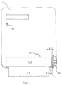
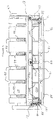
- Figure 1 is a front elevational view of a sheet material dispenser embodying a web transfer mechanism in accordance with the present invention.
- Figure 2 is a left-end elevational view of the dispenser shown in Fig. 1, with a front cover of the dispenser removed.
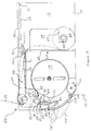
- Figure 3 is an enlarged sectional view taken on line 3-3 in Fig. 1, showing a lower portion of the dispenser (dispenser cover removed) including the web transfer mechanism.
- Figure 4 is a sectional view taken on line 4-4 in Fig. 2, showing the lower portion of the dispenser seen in Fig. 3, with a sensor plate of the web transfer mechanism removed to reveal a stub-roll receptacle.
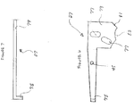
- Figure 5 is a top plan view of the sensor plate of the web transfer mechanism shown in Fig. 3 (and removed from Fig. 4).
- Figure 6 is a side elevational view of a stop arm of the web transfer mechanism shown in Fig. 3.
- Figure 7 is a top plan view of the stop arm shown in Figure 6.
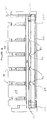
- Figure 8 is an enlarged partial top plan view of a front-end portion of the web transfer mechanism shown in Fig. 3, with structure removed to show clearly a transfer arm in a set position, and a movable front shield in a closed position.
- Figure 9 is an enlarged partial top plan view like Fig. 8, but showing the transfer arm and movable front shield in respective open (loading) positions.
- a dispenser in accordance with the present invention may employ a generally conventional-style exterior dispenser cabinet, e.g., the type used in the commercially available Georgia-Pacific P-12 dispenser.
- the cabinet shown includes a five-sided cover 1 that is pivotally mounted, at a pivot point 3 (see Fig. 2), to a relatively shallow tray-like base member 5.
- Base member 5 has a back wall 7 with appropriate openings (not shown) to accommodate fasteners for attachment of the dispenser to a wall.
- a reserve roll R of flexible sheet material such as paper toweling, may be suitably supported between a pair of cantilever mounted wing members 9 extending from the inside surface of back wall 7. Each wing member carries a cup 11 at its free end, which enters into the opposite ends of the core of reserve roll R.
- the mounting of reserve roll R within the dispenser housing is conventional, and thus no further discussion of this structure is required.
- Additional generally well known features of the dispenser include a lower chassis comprising a pair of side plates 13 extending from back wall 7 along the opposite sides of the dispenser in a lower part thereof. Side plates 13 serve to provide rotatable mounting locations for the feed rollers and other operative components of the dispenser, to be described.
- web material is dispensed in response to a pulling force (tension) being exerted on an exposed free end 15 of a working web 17 (see Fig. 3).
- Pulling of free web end 15 induces main feed roller 19 (see Fig. 3) to rotate a predetermined amount, and a sheet segment of predetermined length to be dispensed and cut by a feed roller mounted, cam actuated, knife of the type disclosed in Rasmussen U.S. Patent No. 4,712,461 (hereby incorporated by reference in its entirety).
- Web material may alternatively be dispensed by rotating a known-type ratchet wheel 21 by hand.
- the web transfer mechanism of the present invention is also useable with various other web feed/cutting mechanisms known in the art.
- a web transfer mechanism 23 in accordance with the present invention is seen clearly in Fig. 3 and includes a pivotable sensor plate 25, a pivotable stop arm 27, a pair of idler rollers 29 and 31, main feed roller 19 and a rotatable transfer arm 33.
- working web 17 comes-off of a working (stub) roll 35 and follows a path extending under sensor plate 25, around upper idler roller 29 and into a feed nip 37 formed between lower roller 31 and main feed roller 19.
- a reserve web 39 extends from reserve roll R (see Fig. 2), over roller 29 (in light contact with working web 17), and terminates with a free end 41 positioned in a space defined between main feed roller 19 and rotatable transfer arm 33.
- a pre-feed portion of the working web path 43, spaced away from (behind and above) feed roller 19, is where the presence or absence of web from working roll 35 is sensed.
- Working roll 35 originates as a reserve roll R that has been partially depleted after dispensing an amount of web material therefrom.
- the degree of depletion of reserve roll R may be visually monitored by opening cover member 1, or by a known type of indicator 47 on the front or side of cover member 1, such as a rotatable color bar or a transparent window.
- reserve roll R (now a stub roll 35) is removed from between wing members 9 and replaced with a new reserve roll. The removed roll is placed in receptacle 49.
- Receptacle 49 is opened by lifting sensor plate 25, which forms a cover over receptacle 49, and working roll 35 is dropped into the receptacle to rest on the floor thereof.
- Sensor plate 25 is lifted by rotating sensor plate 25 about a pivot axis 51 defined between side plates 13, adjacent back wall 7.
- a pair of finger grip holes 53 are provided in sensor plate 25 (see Fig. 5).
- the lower chassis floor is cut-away (open) between side plates 13 in the region of receptacle 49.
- the floor of receptacle 49 is thus formed by the overlapping bottom panel of cover 1, when cover 1 is in its closed position.
- the cores of the web rolls preferably comprise mounting spindles 55 that protrude from the opposite ends of the rolls, and which may become seated within a notch 57 provided in a pair of retaining members 59 provided within receptacle 49.
- retaining members 59 are thin notched plates fixed at their forward ends to a front wall of receptacle 49, and extending toward the rear of receptacle 49. Retaining members 59, with spindles 55, restrain working roll 35 as it is pulled upwards by tension in pre-feed web portion 43, to prevent working roll 35 from being drawn up from under sensor plate 25, especially as working roll 35 reaches the end of working web 17 (which may be glued to spindle 55).
- the forward edge of sensor plate 25 includes a plurality of sensor fingers 61, as best seen in Fig. 5. Sensor fingers 61 extend outwards and downwards from a main panel 63 of sensor plate 25 to rest upon pre-feed portion 43 of the working web 17, in a web-present position. In a web-absent position, sensor plate 25, including fingers 61, is pivoted downwardly by gravity, with fingers 61 entering a plurality of slots 65. Slots 65 are correspondingly located in a generally inverted L-shaped casing member 67 surrounding rear and upper sides of feed roller 19, at the juncture between a vertical casing wall 69 (defining a front wall of receptacle 49), and an adjacent horizontal casing wall 71.
- Casing 67 serves to reinforce and laterally stabilize chassis side plates 13.
- casing 67 provides, on a side opposite receptacle 49, a plurality of arcuate ribs defining an arcuate feed path about the rear side of feed roller 33.
- Sensor plate 25 should be configured to provide a downward force of sensor fingers 61 sufficiently small to avoid interference with feeding of working web 17, e.g., to prevent ripping or tearing of pre-feed portion 43.
- the bias force of plate 25, e.g., the moment created by the distributed weight of the plate must be sufficient to pivot and disengage stop arm 27.
- Using gravity to provide the downward bias of sensor plate 25 has the advantages of simplicity and constancy as compared to a spring which may suffer from fatigue.
- Bias of sensor plate 25 may also be bolstered or supplied using common spring designs. Spring bias would be especially desirable for possible alternative embodiments wherein sensor plate 25 is mounted to have an actuating movement lacking a downward component.
- the pivotal mount of sensor plate 25 adjacent rear wall 25 permits a relatively long lever arm and, since the plate can be readily pivoted to an open position, permits easy placement of a stub roll in receptacle 49.
- sensor plate 25 senses the absence of web from working roll 35 at a pre-feed portion spaced sufficiently from the operation of feed roller 19 (and integral cutting knife) and rotatable transfer arm 33 to prevent malfunction and interference, yet close enough to feed roller 19 to minimize double feed of web at the time of transfer.
- a web sensor that senses the presence or absence of web material at the main feed roller would be prone to interfere with the feed roller incorporated knife as it emerges, resulting in a malfunction of one or both of the cutting knife and sensing mechanism. The present invention avoids this difficulty.
- a proper threading of the web under the sensor plate is simple and not prone to faulty configuration, because the sensor plate 25 is necessarily raised to permit placement of a stub roll in receptacle 49. Plate 25 is automatically placed in a proper sensing position upon a closure of receptacle 49, by simply permitting plate 25 to drop into position.
- Web transfer mechanism 23 of the present invention is well suited for (but not limited to) use in conjunction with a dispenser that includes a cutting blade mounted within a feed roller, such as is disclosed in the Rasmussen '464 patent, and embodied in the P-12 dispenser commercially available from Georgia- Pacific.
- a dispenser that includes a cutting blade mounted within a feed roller, such as is disclosed in the Rasmussen '464 patent, and embodied in the P-12 dispenser commercially available from Georgia-Pacific.
- rotation of the feed roller through a dispensing cycle is initiated by a user pulling on the exposed leading end of web.
- the pulling of the web through one-half of a dispensing cycle loads a spring (not shown) which serves to carry the feed roller through the remainder of a dispensing cycle.
- a cutting blade is slidably mounted within the feed roller and progressively emerges from the feed roller in response to rotation of the feed roller.
- the present web transfer mechanism is well suited for use with such dispensers because the sensor plate 33 is located at the pre-feed portion 43 of the working web 17 positioned away from feed roller 19 (and the cutting knife action). Also, the present invention may advantageously be adapted or retrofit to existing dispensers such as the Georgia Pacific P-12 dispenser, without the need to alter the configuration of main feed roller 19 and its cutting blade, as well as other components.
- sensor plate 25 also includes a coupling tab or overhang 73 attached at a forward corner of main panel 63.
- Tab 73 extends forwardly so as to overlap with a rear coupling end 75 of stop arm 27.
- Coupling tab 73 may be of various sizes and shapes allowing it to push downwardly on coupling end 75.
- Stop arm 27 is preferably constructed of a thin plate having a generally mallet-like shape, as seen in Figs. 3, 6 and 7. Coupling end 75 of arm 27 extends perpendicularly out of the plane of the remainder of stop arm 27 (see Fig. 7) and serves to engage the underside of coupling tab 73 of sensor plate 25. Formed in a "head" portion of the mallet-like shape of stop arm 27 are a pair of elongated slots 77 with rounded ends which are received on the axes of rollers 29 and 31, and which permit a limited range of pivotal motion of stop arm 27. Stop arm 27 is mounted adjacent left side plate 13, to which it is pivotably affixed by pin 45.
- Rollers 29 and 31 span the distance between the pair of side plates 13 and each has an axial shaft that fixes rollers 29 and 31 between side plates 13. Stop end 79 of stop arm 27 is fitted within a narrow clearance between the left ends of rollers 29 and 31, and the left side plate 13. Lateral motion of stop arm 27 is restrained within this narrow clearance. Slots 77 provide space for the movement of stop end 79 with respect to the axial shafts of each of rollers 29 and 31, and limit the amount of rotation about axis pin 45, thereby restraining the pivotable motion of stop arm 27.
- Stop end 79 of stop arm 27 includes an arcuate edge surface 81 generally facing downward and outward of the dispenser. Edge surface 81 engages an opposing edge of rotatable transfer arm 33 when stop arm 27 is in the hold position. This engagement holds transfer arm 33 (against a spring bias thereof--to be described) in a set position until coupling end 75 of stop arm 27 is depressed by coupling tab 73 to pivot stop arm 27 slightly counterclockwise into the release position. In the release position, stop arm 27 has rotated slightly about the pivot axis defined by pin 45 in response to the downward motion of coupling tab 73, and stop end 79 has moved upward, causing disengagement from transfer arm 33.
- Arcuate edge surface 81 allows an opposing edge of transfer arm 33 to slide therealong until such point that a lower terminus of edge surface 81 is reached, at the tip of a lobe formed between arcuate edge surface 81 and a second arcuate edge surface 83, whereupon transfer arm 33 is released to move under spring bias into a transfer position 33'.
- rotatable transfer arm 33 includes a pair of spaced lever arms 85 pivoted on respective pivot pins 87 (see Fig. 3) protruding from opposite lateral sides of a stationary bracing 94 supported between side plates 13, in front of main feed roller 19.
- Bracing 94 provides on its inside surface (facing main feed roller 19) continuations of web material stripper bars 99 extending into feed roller grooves 95.
- a transfer bar 89 is attached to and extends the length of feed roller 19 between and slightly beyond arms 85, and four blunt transfer fingers 91 (angled upwardly in the open position shown in Fig. 9) are spaced along a leading edge of transfer bar 89.
- a strengthening rib 92 extends along a trailing edge of transfer bar 89.
- Transfer arm 33 is biased towards the transfer position 33' (see Fig. 3) by a transfer spring 93 (see Fig. 9) mounted adjacent one or both of side plates 13 (both sides as shown), and pressing against an underside of one (or both) of spaced lever arms 85.
- springs 93 comprise wire spring arms mounted to stationary bracing 94 extending between side plates 13.
- a pair of 0.8 mm steel wire spring arms 93 should suffice to provide a suitable small upward biasing force on lever arms 85.
- a spring arm with coils providing additional biasing force may be utilized.
- Spring 93 has a main arm portion which when bent creates the biasing spring force, a base leg portion extending in a first direction perpendicular to the main arm portion and terminating with a fixation eye, and a perpendicular arm-contacting portion at the opposite end of the main arm portion extending in a second direction opposite to the extending direction of the base leg portion.
- Transfer fingers 91 correspond in position to four circumferential grooves 95 provided in main feed roller 19.
- transfer arm 33 is restrained in a set position by the stop arm 27, and upon release moves forward into web transfer position 33' (see Fig. 3), which movement effects a transfer operation, as described below.
- Web 39 from reserve roll R is prepositioned to extend downward in front of upper idler roller 29 and into a space defined between a stationary shield plate 97 attached to a front side of stationary bracing 94 (see Figs. 3 and 9) and transfer arm 33 placed in the set position, adjacent to, or in light contact with, transfer fingers 91.
- transfer arm 33 Upon release of transfer arm 33, a leading end portion of reserve web 39 is pushed toward main feed roller 19, by transfer fingers 91.
- transfer fingers 91 In the transfer position 33', transfer fingers 91 have forced contacted web portions of web 39 into or adjacent transfer feed roller grooves 95, and into contact with the outer surface of feed roller 19.
- a leading end portion of web 39 from reserve roll R is drawn into feed nip 37.
- rotation of feed roller 19 simultaneously draws web 39 into nip 37.
- the web travels around the backside of feed roller 19, to about a 5:00 position, where the web is stripped-off the feed roller 19, by stripper bars 99 (see Fig. 9), and emerges from the dispensing slot adjacent exit roller 101, thereby completing the transfer of feed to the reserve roll R.
- reserve roll R can be placed into receptacle 49 where it becomes working roll 35, and a new reserve roll R may be installed in the manner previously described.
- Dispenser maintenance i.e., removing a spent stub roll 35 from receptacle 49, relocating a partially depleted roll from between wing members 9 to receptacle 49, and installing a new reserve roll between wing member 9, is simplified by way of a movable shield 103 located in front of stationary shield plate 97, as best seen in Figs. 1, 3, 8 and 9.
- movable shield 103 is partially exposed through a laterally elongated port 105 formed in dispenser cover 1.
- Shield 103 is arc-shaped in profile, and presents a smooth arcuate face on the lower front of the dispenser during normal operation. The exposed leading web end 15 emerges from the dispenser between exit roller 101 and the lower edge of shield cover 103.
- cover 103 As seen in Figs. 3 and 9, the lower edge of cover 103 is hingedly connected to side plates 13 via a pair of pivot pins/holes 107, and the main arcuate panel of cover 103 is strengthened by spaced arcuate ribs 109 provided on its inside surface. Shield 103 is biased to rotate outwardly to an open position (counter-clockwise as viewed in Fig. 3) by a spring 111 (see Fig. 9).
- Spring 111 may be a flat leaf spring having an overall L-shape which presses against the inside of cover 103, between a central pair of support ribs 109.
- Spring 111 is mounted on stationary bracing 94 by a screw 117 extending through a short mounting tab, so that a perpendicular main arm portion extends upwardly in contact with the arcing inner contour of shield 103.
- Spring 111 may comprise an L-shaped base member providing the mounting tab, and a separate flat strip of spring metal secured thereto to provide the main arm portion.
- Other spring configurations, including an equivalently functioning single or double coil spring, could be substituted.
- yoke-like arm guides 121 extend inwardly from the top edge of the main panel of shield 103, at respective spaced locations that correspond to arms 85 of transfer arm 33.
- Guides 121 form rectangular slots 123 surrounding and confining the movement of spaced arms 85. The arrangement provides a partial coupling of the transfer arms 33 to the movement of shield 103, as will be apparent from the following description of dispenser operation.
- cover port 105 is sized to be shorter in length than shield 103, movable shield 103 cannot pass therethrough and is thus retained (against the bias of spring 111) in the closed position shown in Fig. 8, so long as cover 1 is in its closed position.
- a custodian seeking to install a new reserve roll R will unlock cover 1 and swing it open by gripping its top and rotating it downwardly about pivot point 3.
- any depleted roll core retained in receptacle 49 (on the floor formed by the bottom panel of cover 1) will roll forward by gravity within opened cover 1, thus presenting itself for easy removal.
- Such action occurs by virtue of the open bottom of receptacle 49, and the inclined orientation of cover 1 in the open position.
- shield 103 is released to rotate counterclockwise to the open position shown in Fig. 9 (and labeled 103' in Fig. 3).
- the inside end surfaces of slots 123 of arm guides 121 contact the opposing edges of lever arms 85.
- Spring 111 biases movable shield 103 outwardly, and overcomes the relatively weaker opposing bias of springs 93 acting on arms 85.
- arm guides 121 pull arms 85 forwardly to pivot transfer bar 33 outwardly, with the inside ends of slots 123 sliding upwardly along arms 85.
- transfer bar 33 is retracted into the open (loading) position shown in Fig. 9 (and labeled 33" in Fig. 3) spaced a maximum distance away from feed nip 37.
- the opening of cover 1 allows movable shield 103 to open, and transfer arm 33 to retract away from the feed nip, thereby presenting a large, easily accessible opening for pre-transfer placement and retention of the leading end portion of a new reserve roll R.
- setting of the dispenser for a subsequent transfer is a simple matter of passing the leading web end portion over idler roller 29 and placing the same between stationary plate 97 and pivotable transfer arm 33 (retracted to position 33").
- the dispenser is then returned to a normal dispensing condition by simply swinging cover member 1 closed. Closure of cover member 1 automatically locks shield 103 in its closed position, and returns transfer arm 33 to its set position (see Figs. 3 and 8), retained by stop arm 27, until a release thereof by sensor plate 25 upon depletion of the stub roll.
- the components of the inventive web transfer mechanism may be manufactured using known materials and manufacturing techniques.
- durable lightweight thermoplastic material e.g., ABS, and injection molding
- transfer arm 85 has glass fiber (e.g., 30%) added to the thermoplastic resin to increase the stiffness thereof.
- main feed roller 19 preferably has a construction as described in Rasmussen U.S. Patent No. 4,712,461 (and incorporated into the Georgia-Pacific P-12 dispenser).
- the remaining rollers may comprise molded plastic hubs on mounted circular steel shafts.
- suitable materials, configurations and manufacturing methods will be apparent to those skilled in the art.
Landscapes
- Health & Medical Sciences (AREA)
- Public Health (AREA)
- Replacement Of Web Rolls (AREA)
Applications Claiming Priority (2)
| Application Number | Priority Date | Filing Date | Title |
|---|---|---|---|
| US435718 | 1995-05-05 | ||
| US09/435,718 US6826991B1 (en) | 1999-11-08 | 1999-11-08 | Web transfer mechanism for flexible sheet dispenser |
Publications (2)
| Publication Number | Publication Date |
|---|---|
| EP1097665A2 true EP1097665A2 (fr) | 2001-05-09 |
| EP1097665A3 EP1097665A3 (fr) | 2003-01-02 |
Family
ID=23729555
Family Applications (1)
| Application Number | Title | Priority Date | Filing Date |
|---|---|---|---|
| EP00309882A Withdrawn EP1097665A3 (fr) | 1999-11-08 | 2000-11-07 | Mécanisme de transfert de bande pour distributeur de feuilles flexibles |
Country Status (2)
| Country | Link |
|---|---|
| US (2) | US6826991B1 (fr) |
| EP (1) | EP1097665A3 (fr) |
Cited By (8)
| Publication number | Priority date | Publication date | Assignee | Title |
|---|---|---|---|---|
| US6607160B2 (en) | 2001-07-30 | 2003-08-19 | Kimberly-Clark Worldwide | Easy loading dispenser |
| WO2009135236A1 (fr) * | 2008-05-05 | 2009-11-12 | Hans Georg Hagleitner | Distributeur de papier |
| US8800415B2 (en) | 2011-04-06 | 2014-08-12 | Solaris Paper, Inc. | Transfer mechanism for sheet material dispenser |
| US9756992B2 (en) | 2013-03-15 | 2017-09-12 | Vsi Import Solutions, Llc | Electronic residential tissue dispenser |
| US9907441B2 (en) | 2014-04-18 | 2018-03-06 | Vsi Import Solutions, Llc | Electronic residential tissue dispenser |
| CN108289575A (zh) * | 2015-11-16 | 2018-07-17 | Sca卫生用品公司 | 卷的分配器 |
| US10835086B2 (en) | 2018-04-09 | 2020-11-17 | Charles A. Osborne, JR. | Sheet material transfer system/assembly for a dispenser |
| US11478111B2 (en) | 2019-06-14 | 2022-10-25 | Valve Solutions, Inc. | Loading and transfer system/assembly for sheet material dispensers |
Families Citing this family (50)
| Publication number | Priority date | Publication date | Assignee | Title |
|---|---|---|---|---|
| US9010602B2 (en) | 2002-02-15 | 2015-04-21 | Georgia-Pacific Consumer Products Lp | Towel dispenser |
| US20050109789A1 (en) * | 2003-05-14 | 2005-05-26 | Katsumi Nagayoshi | Roll paper feeder |
| US7971813B2 (en) | 2004-07-27 | 2011-07-05 | Owens Corning Intellectual Capital, Llc | Blowing machine for loosefill insulation material |
| US7938348B2 (en) | 2004-07-27 | 2011-05-10 | Owens Corning Intellectual Capital, Llc | Loosefill blowing machine with a chute |
| US7380748B2 (en) * | 2004-12-14 | 2008-06-03 | Georgia-Pacific Consumer Products Lp | Towel dispenser with improved drive roll and improved dispensing chute |
| US7597219B2 (en) * | 2005-12-16 | 2009-10-06 | Owens Corning Intellectual Capital, Llc | Rotary valve for handling solid particulate material |
| US7913842B2 (en) | 2006-10-16 | 2011-03-29 | Owens Corning Intellectual Capital, Llc | Loosefill package for blowing wool machine |
| US7712690B2 (en) | 2006-10-16 | 2010-05-11 | Owens Corning Intellectual Capital, Llc | Exit valve for blowing insulation machine |
| US7882947B2 (en) | 2006-10-16 | 2011-02-08 | Owens Corning Intellectual Capital, Llc | Partially cut loosefill package |
| US7845585B2 (en) | 2006-10-16 | 2010-12-07 | Owens Corning Intellectual Capital, Llc | Blowing wool machine outlet plate assembly |
| US7819349B2 (en) | 2006-10-16 | 2010-10-26 | Owens Corning Intellectual Capital, Llc | Entrance chute for blowing insulation machine |
| US7731115B2 (en) | 2006-10-16 | 2010-06-08 | Owens Corning Intellectual Capital, Llc | Agitation system for blowing insulation machine |
| US11297984B2 (en) | 2006-10-31 | 2022-04-12 | Gpcp Ip Holdings Llc | Automatic napkin dispenser |
| FR2907654B1 (fr) | 2006-10-31 | 2010-01-29 | Georgia Pacific France | Procede, dispositif de fabrication et rouleaux associes formes de feuilles a decoupes et predecoupes alternees |
| US7887005B2 (en) | 2007-09-12 | 2011-02-15 | Innovia Intellectual Properties, Llc | Easy-load household automatic paper towel dispenser |
| US8833691B1 (en) | 2007-12-21 | 2014-09-16 | Georgia-Pacific Consumer Products Lp | Product, dispenser and method of dispensing product |
| CN101883514A (zh) * | 2007-12-21 | 2010-11-10 | 佐治亚-太平洋消费产品有限合伙公司 | 产品、分配器以及分配产品的方法 |
| US7762484B2 (en) | 2008-04-14 | 2010-07-27 | Owens Corning Intellectual Capital, Llc | Blowing wool machine flow control |
| US7971814B2 (en) | 2008-12-17 | 2011-07-05 | Owens Corning Intellectual Capital, Llc | Non-symmetrical airlock for blowing wool machine |
| US20100286818A1 (en) * | 2009-05-08 | 2010-11-11 | Georgia-Pacific Consumer Products Lp | Sheet product dispenser with sensor for sheet separation |
| US8616489B2 (en) | 2009-05-08 | 2013-12-31 | Georgia-Pacific Consumer Products Lp | Sheet product dispenser |
| WO2010141931A2 (fr) | 2009-06-06 | 2010-12-09 | Innovia Intellectual Properties, Llc | Appareil de distribution automatique d'essuie-mains en papier |
| US7886904B1 (en) | 2009-07-30 | 2011-02-15 | Owens Corning Intellectual Capital, Llc | Loosefill package for blowing wool machine |
| US9457355B2 (en) | 2011-09-16 | 2016-10-04 | Omachron Intellectual Property Inc. | Apparatus for converting bales of insulation to loose fill |
| US10383489B2 (en) | 2012-02-10 | 2019-08-20 | Gpcp Ip Holdings Llc | Automatic napkin dispenser |
| US9326648B2 (en) | 2013-06-13 | 2016-05-03 | Dispensing Dynamics International | Dispensing system for consecutively dispensing paper sheet material from a stub roll and a primary roll |
| US10602887B2 (en) | 2013-08-23 | 2020-03-31 | Gpcp Ip Holdings Llc | Towel dispensers |
| US9596964B1 (en) | 2013-08-23 | 2017-03-21 | Innovia Intellectual Properties, Llc | Wall mounted towel dispensers |
| US9642503B1 (en) | 2013-08-25 | 2017-05-09 | Innovia Intellectual Properties, Llc | Portable, vertically oriented automatic towel dispenser apparatus |
| US9604811B2 (en) | 2013-10-01 | 2017-03-28 | Georgia-Pacific Consumer Products Lp | Automatic paper product dispenser with data collection and method |
| US9854948B1 (en) | 2015-03-31 | 2018-01-02 | Wisconsin Plastics, Inc. | Paper towel dispenser |
| US10342395B2 (en) | 2015-08-28 | 2019-07-09 | Gpcp Ip Holdings Llc | Sheet product dispenser with product level gauge system |
| MX2018002486A (es) | 2015-08-31 | 2018-11-29 | Gpcp Ip Holdings Llc | Dispensadores de productos tipo hoja con acumulacion reducida de productos tipo hoja y metodos relacionados. |
| US11412900B2 (en) | 2016-04-11 | 2022-08-16 | Gpcp Ip Holdings Llc | Sheet product dispenser with motor operation sensing |
| US11395566B2 (en) | 2016-04-11 | 2022-07-26 | Gpcp Ip Holdings Llc | Sheet product dispenser |
| US10952569B2 (en) | 2017-05-10 | 2021-03-23 | Gpcp Ip Holdings Llc | Premature replacement prevention or deterrence for multiple roll sheet product dispensers |
| US10575686B2 (en) | 2017-05-10 | 2020-03-03 | Gpcp Ip Holdings Llc | Automatic paper product dispenser and associated methods |
| US10506901B2 (en) | 2017-06-23 | 2019-12-17 | Gpcp Ip Holdings Llc | Sheet product dispenser with product level indicator calibration |
| US10040660B1 (en) | 2017-07-17 | 2018-08-07 | Gpcp Ip Holdings Llc | Power device for a product dispenser |
| US10850938B2 (en) | 2017-10-09 | 2020-12-01 | Gpcp Ip Holdings Llc | Mechanical sheet product dispenser |
| US10660485B2 (en) | 2017-10-09 | 2020-05-26 | Gpcp Ip Holdings Llc | Dual roll product dispenser with rotating refill carriage |
| EP3761839B1 (fr) | 2018-03-08 | 2023-09-06 | Dispensing Dynamics International, Inc. | Système de distributeur à rouleau de faible diamètre |
| WO2020123491A1 (fr) | 2018-12-12 | 2020-06-18 | Osborne Charles Agnew Jr | Ensemble de distribution destiné à distribuer sélectivement une pluralité de réserves de matériau en feuille roulé |
| US11534037B2 (en) | 2019-03-04 | 2022-12-27 | Gpcp Ip Holdings Llc | Automated wetted or dry sheet product dispensers |
| WO2020210541A1 (fr) | 2019-04-12 | 2020-10-15 | Dispensing Dynamics International, Inc. | Distributeur avec chute automatique de rouleau souche |
| US11479431B2 (en) * | 2019-07-19 | 2022-10-25 | Dispensing Dynamics International, Inc. | Dispensing systems with floating support rollers |
| WO2021221643A1 (fr) | 2020-04-30 | 2021-11-04 | Kimberly-Clark Worldwide, Inc. | Distributeur doté d'un élément d'abaissement et procédé associé |
| US11903532B2 (en) | 2020-11-23 | 2024-02-20 | Gpcp Ip Holdings Llc | Product removal switch shuttle for product dispensers |
| CA3248020A1 (fr) | 2022-02-08 | 2023-08-17 | Valve Solutions, Inc. | Ensemble distributeur de matériau en feuille pour distribuer sélectivement un matériau en feuille à partir d'une pluralité d'alimentations en matériau en feuille laminée |
| USD1118201S1 (en) | 2022-09-30 | 2026-03-17 | Vsi Health And Hygiene Group, Llc | Dispenser |
Citations (10)
| Publication number | Priority date | Publication date | Assignee | Title |
|---|---|---|---|---|
| US2930663A (en) | 1955-01-19 | 1960-03-29 | Raymond L Weiss | Towel dispenser |
| US3269592A (en) | 1963-09-26 | 1966-08-30 | Alwin Mfg Company | Universal towel dispenser |
| US3288387A (en) | 1964-12-08 | 1966-11-29 | Jr William J Craven | Paper towel dispenser |
| US3628743A (en) | 1969-11-04 | 1971-12-21 | Scott Paper Co | Dispensing cabinet for sheet material |
| US3858951A (en) | 1972-03-29 | 1975-01-07 | Georgia Pacific Corp | Towel dispenser |
| US3917191A (en) | 1972-04-12 | 1975-11-04 | Fort Howard Paper Co | Paper towel dispenser and transfer mechanism |
| US4165138A (en) | 1976-11-15 | 1979-08-21 | Mosinee Paper Company | Dispenser cabinet for sheet material and transfer mechanism |
| US4378912A (en) | 1981-11-12 | 1983-04-05 | Crown Zellerbach Corporation | Sheet material dispenser apparatus |
| US4712461A (en) | 1985-10-18 | 1987-12-15 | Georgia-Pacific Corporation | Rolled material dispenser with feed roller containing a sliding cutter |
| US5526973A (en) | 1992-12-02 | 1996-06-18 | Georgia-Pacific Corporation | Automatic web transfer mechanism for flexible sheet dispenser |
Family Cites Families (26)
| Publication number | Priority date | Publication date | Assignee | Title |
|---|---|---|---|---|
| US2930664A (en) * | 1957-03-18 | 1960-03-29 | American Linen Supply Company | Towel dispensing apparatus and method |
| US3007650A (en) | 1959-01-12 | 1961-11-07 | Crown Zellerbach Corp | Two-roll towel dispensing cabinet |
| US4067509A (en) * | 1973-08-27 | 1978-01-10 | Fort Howard Paper Company | Paper towel dispenser and transfer mechanism |
| US4010909A (en) * | 1975-09-15 | 1977-03-08 | Scott Paper Company | Dispensing cabinet for sheet material |
| CH615818A5 (fr) * | 1977-04-19 | 1980-02-29 | Apura Gmbh | |
| US4106684A (en) * | 1977-08-26 | 1978-08-15 | Crown Zellerbach Corporation | Sheet material dispensing device |
| US4317547A (en) * | 1980-07-07 | 1982-03-02 | Fleck Industries, Inc. | Transfer paper towel dispenser |
| US4396163A (en) * | 1980-07-07 | 1983-08-02 | Fleck Industries, Inc. | Lever operated transfer towel dispenser |
| US4358169A (en) * | 1980-07-25 | 1982-11-09 | Griffith-Hope Company | Dispenser for coiled sheet material |
| US4403748A (en) * | 1981-08-27 | 1983-09-13 | Griffith-Hope Company | Dispenser for coiled material having improved transfer mechanism |
| US4487375A (en) * | 1983-02-16 | 1984-12-11 | Georgia-Pacific Corporation | Roll transfer mechanism for web material dispenser |
| FR2583729B1 (fr) | 1985-06-20 | 1987-09-18 | Granger Maurice | Appareil simplifie de distribution et de coupe simultanees de bandes de materiaux enroules avec changement automatique du rouleau en service. |
| US4611768A (en) * | 1985-07-01 | 1986-09-16 | Mosinee Paper Corporation | Modular paper towel dispenser |
| US4756485A (en) | 1987-03-11 | 1988-07-12 | Scott Paper Company | Dispenser for multiple rolls of sheet material |
| US4846412A (en) | 1987-12-03 | 1989-07-11 | Wyant & Company Limited | Two roll sheet material dispenser |
| US4807824A (en) | 1988-06-27 | 1989-02-28 | James River Ii, Inc. | Paper roll towel dispenser |
| DE4004122A1 (de) | 1990-02-10 | 1991-08-14 | Feldmuehle Gmbh Scott | Vorrichtung zum ausgeben von bahnabschnitten |
| CA2039382C (fr) * | 1991-03-12 | 1999-01-05 | Paul A. Omdoll | Distributeur de materiau en feuille conditionne en rouleau |
| US5302167A (en) | 1991-07-30 | 1994-04-12 | Scott Paper Company | Embossing dispenser roll transfer assembly |
| GB2267271B (en) | 1992-05-28 | 1995-05-31 | Fort Howard Corp | Dispenser for multiple rolls of sheet material |
| US5558302A (en) | 1995-02-07 | 1996-09-24 | Georgia-Pacific Corporation | Flexible sheet material dispenser with automatic roll transferring mechanism |
| US5772291A (en) | 1996-02-16 | 1998-06-30 | Mosinee Paper Corporation | Hands-free paper towel dispensers |
| FR2746621B1 (fr) | 1996-03-29 | 1998-04-24 | Granger Maurice | Appareil distributeur de materiau d'essuyage avec dispositif de chargement d'un rouleau en reserve |
| FR2771620B1 (fr) | 1997-12-01 | 1999-12-31 | Maurice Granger | Appareil distributeur de papier d'essuyage |
| US6354533B1 (en) * | 1999-08-25 | 2002-03-12 | Georgia-Pacific Corporation | Web transfer mechanism for flexible sheet dispenser |
| US6145779A (en) * | 1999-09-23 | 2000-11-14 | Kimberly-Clark Worldwide, Inc. | Dual roll transfer dispenser |
-
1999
- 1999-11-08 US US09/435,718 patent/US6826991B1/en not_active Expired - Fee Related
-
2000
- 2000-11-07 EP EP00309882A patent/EP1097665A3/fr not_active Withdrawn
-
2004
- 2004-11-01 US US10/976,867 patent/US7270292B2/en not_active Expired - Lifetime
Patent Citations (10)
| Publication number | Priority date | Publication date | Assignee | Title |
|---|---|---|---|---|
| US2930663A (en) | 1955-01-19 | 1960-03-29 | Raymond L Weiss | Towel dispenser |
| US3269592A (en) | 1963-09-26 | 1966-08-30 | Alwin Mfg Company | Universal towel dispenser |
| US3288387A (en) | 1964-12-08 | 1966-11-29 | Jr William J Craven | Paper towel dispenser |
| US3628743A (en) | 1969-11-04 | 1971-12-21 | Scott Paper Co | Dispensing cabinet for sheet material |
| US3858951A (en) | 1972-03-29 | 1975-01-07 | Georgia Pacific Corp | Towel dispenser |
| US3917191A (en) | 1972-04-12 | 1975-11-04 | Fort Howard Paper Co | Paper towel dispenser and transfer mechanism |
| US4165138A (en) | 1976-11-15 | 1979-08-21 | Mosinee Paper Company | Dispenser cabinet for sheet material and transfer mechanism |
| US4378912A (en) | 1981-11-12 | 1983-04-05 | Crown Zellerbach Corporation | Sheet material dispenser apparatus |
| US4712461A (en) | 1985-10-18 | 1987-12-15 | Georgia-Pacific Corporation | Rolled material dispenser with feed roller containing a sliding cutter |
| US5526973A (en) | 1992-12-02 | 1996-06-18 | Georgia-Pacific Corporation | Automatic web transfer mechanism for flexible sheet dispenser |
Cited By (14)
| Publication number | Priority date | Publication date | Assignee | Title |
|---|---|---|---|---|
| US6607160B2 (en) | 2001-07-30 | 2003-08-19 | Kimberly-Clark Worldwide | Easy loading dispenser |
| WO2009135236A1 (fr) * | 2008-05-05 | 2009-11-12 | Hans Georg Hagleitner | Distributeur de papier |
| US8448890B2 (en) | 2008-05-05 | 2013-05-28 | Hans Georg Hagleitner | Paper dispenser |
| US8910898B2 (en) | 2008-05-05 | 2014-12-16 | Hans Georg Hagleitner | Paper dispenser |
| US8800415B2 (en) | 2011-04-06 | 2014-08-12 | Solaris Paper, Inc. | Transfer mechanism for sheet material dispenser |
| US10123665B2 (en) | 2013-03-15 | 2018-11-13 | Valve Solutions, Inc. | Electronic residential tissue dispenser |
| US9756992B2 (en) | 2013-03-15 | 2017-09-12 | Vsi Import Solutions, Llc | Electronic residential tissue dispenser |
| US9907441B2 (en) | 2014-04-18 | 2018-03-06 | Vsi Import Solutions, Llc | Electronic residential tissue dispenser |
| US10136769B2 (en) | 2014-04-18 | 2018-11-27 | Valve Solutions, Inc. | Electronic residential tissue dispenser |
| CN108289575A (zh) * | 2015-11-16 | 2018-07-17 | Sca卫生用品公司 | 卷的分配器 |
| US10835086B2 (en) | 2018-04-09 | 2020-11-17 | Charles A. Osborne, JR. | Sheet material transfer system/assembly for a dispenser |
| US11478111B2 (en) | 2019-06-14 | 2022-10-25 | Valve Solutions, Inc. | Loading and transfer system/assembly for sheet material dispensers |
| US11864695B2 (en) | 2019-06-14 | 2024-01-09 | Valve Solutions, Inc. | Loading and transfer system/assembly for sheet material dispensers |
| US12161269B2 (en) | 2019-06-14 | 2024-12-10 | Valve Solutions, Inc. | Loading and transfer system/assembly for sheet material dispensers |
Also Published As
| Publication number | Publication date |
|---|---|
| US6826991B1 (en) | 2004-12-07 |
| EP1097665A3 (fr) | 2003-01-02 |
| US7270292B2 (en) | 2007-09-18 |
| US20050056721A1 (en) | 2005-03-17 |
Similar Documents
| Publication | Publication Date | Title |
|---|---|---|
| US6826991B1 (en) | Web transfer mechanism for flexible sheet dispenser | |
| US6354533B1 (en) | Web transfer mechanism for flexible sheet dispenser | |
| US5375785A (en) | Automatic web transfer mechanism for flexible sheet dispenser | |
| EP1411807B1 (fr) | Distributeur a chargement facilite | |
| CA2092585C (fr) | Distributeur de serviette en papier perfore | |
| US6237871B1 (en) | Paper towel transfer apparatus | |
| US4165138A (en) | Dispenser cabinet for sheet material and transfer mechanism | |
| US5009313A (en) | Bathroom tissue dispenser (spindle release) | |
| US8555761B2 (en) | Paper sheet material dispenser apparatus | |
| US10299638B2 (en) | Dispenser | |
| US5294192A (en) | Dispenser for rolled sheet material | |
| US4403748A (en) | Dispenser for coiled material having improved transfer mechanism | |
| US4358169A (en) | Dispenser for coiled sheet material | |
| US5078033A (en) | Flexible sheet material dispenser | |
| CA1288395C (fr) | Debiteur a plusieurs rouleaux de materiaux en feuille | |
| AU2002245729A1 (en) | Easy loading dispenser | |
| US20110068129A1 (en) | Sheet roll dispenser | |
| US6860447B2 (en) | Dispenser for web paper product | |
| JPH0654777A (ja) | ペーパータオルディスペンサー | |
| EP0298931B1 (fr) | Appareil distributeur d'essuie-main en papier enroulé avec rouleau de remplacement | |
| US6766976B2 (en) | Dispenser for rolls of web material | |
| EP0461732B1 (fr) | Distributeur pour de multiples rouleaux de matériau en feuille | |
| EP1435819B1 (fr) | Distributeur de rouleaux de materiau en bande |
Legal Events
| Date | Code | Title | Description |
|---|---|---|---|
| PUAI | Public reference made under article 153(3) epc to a published international application that has entered the european phase |
Free format text: ORIGINAL CODE: 0009012 |
|
| AK | Designated contracting states |
Kind code of ref document: A2 Designated state(s): AT BE CH CY DE DK ES FI FR GB GR IE IT LI LU MC NL PT SE TR |
|
| AX | Request for extension of the european patent |
Free format text: AL;LT;LV;MK;RO;SI |
|
| PUAL | Search report despatched |
Free format text: ORIGINAL CODE: 0009013 |
|
| AK | Designated contracting states |
Kind code of ref document: A3 Designated state(s): AT BE CH CY DE DK ES FI FR GB GR IE IT LI LU MC NL PT SE TR |
|
| AX | Request for extension of the european patent |
Free format text: AL;LT;LV;MK;RO;SI |
|
| AKX | Designation fees paid | ||
| REG | Reference to a national code |
Ref country code: DE Ref legal event code: 8566 |
|
| STAA | Information on the status of an ep patent application or granted ep patent |
Free format text: STATUS: THE APPLICATION IS DEEMED TO BE WITHDRAWN |
|
| 18D | Application deemed to be withdrawn |
Effective date: 20030703 |