EP1097677A2 - Vorrichtung zum Festlegen eines Dentalmodelles an den Armen eines Artikulators - Google Patents
Vorrichtung zum Festlegen eines Dentalmodelles an den Armen eines Artikulators Download PDFInfo
- Publication number
- EP1097677A2 EP1097677A2 EP00123875A EP00123875A EP1097677A2 EP 1097677 A2 EP1097677 A2 EP 1097677A2 EP 00123875 A EP00123875 A EP 00123875A EP 00123875 A EP00123875 A EP 00123875A EP 1097677 A2 EP1097677 A2 EP 1097677A2
- Authority
- EP
- European Patent Office
- Prior art keywords
- coupling elements
- support
- arms
- clamping
- mounting plate
- Prior art date
- Legal status (The legal status is an assumption and is not a legal conclusion. Google has not performed a legal analysis and makes no representation as to the accuracy of the status listed.)
- Granted
Links
- 230000008878 coupling Effects 0.000 claims description 58
- 238000010168 coupling process Methods 0.000 claims description 58
- 238000005859 coupling reaction Methods 0.000 claims description 58
- 238000003754 machining Methods 0.000 claims 1
- 230000000694 effects Effects 0.000 description 3
- 239000011505 plaster Substances 0.000 description 3
- 238000010276 construction Methods 0.000 description 2
- 238000006073 displacement reaction Methods 0.000 description 2
- 238000005516 engineering process Methods 0.000 description 2
- 238000000034 method Methods 0.000 description 2
- 230000005540 biological transmission Effects 0.000 description 1
Images


Classifications
-
- A—HUMAN NECESSITIES
- A61—MEDICAL OR VETERINARY SCIENCE; HYGIENE
- A61C—DENTISTRY; APPARATUS OR METHODS FOR ORAL OR DENTAL HYGIENE
- A61C11/00—Dental articulators, i.e. for simulating movement of the temporo-mandibular joints; Articulation forms or mouldings
- A61C11/08—Dental articulators, i.e. for simulating movement of the temporo-mandibular joints; Articulation forms or mouldings with means to secure dental casts to articulator
Definitions
- the invention relates to a device for setting a dental model on the arms of a Articulator or on a processing arrangement with a mounting plate that on the arm of the Articulator or a processing arrangement can be fastened in the correct position and with a Distance to the mounting plate provided for the dental model and for the Attachment of the same, the support plate being adjustable relative to the mounting plate is executed.
- So-called articulators are used in dental technology. Such an articulator is, for example shown and described in AT-B-393077. Plaster is used on a model plate or a plaster-like mass, the dental model (dentures) and the model plate then attached to the arms of the articulator in the correct position. This is done by the dental technician. The dental prosthesis manufactured by the dental technician is transferred to the dentist, who in turn is the dentist Dental technicians manufactured dentures also checked with an articulator, delivered. For this The dentist also had to test the dental model or denture with plaster or one Set the plaster-like mass on a model plate and then position it again in the correct position attach the arms of an articulator.
- the present invention has therefore set itself the task in a device of the beginning mentioned type the adjustment options between the mounting plate and support plate significantly improve and make the mutual fixation in the desired position more effective and to simplify handling.
- both on the mounting plate and on the support plate cantilevered arms arranged on both sides with coupling elements are and a pair of support rails with their corresponding to the coupling elements Executed ends grasp the coupling elements on the cantilevered arms, and that the two support rails can be tightened against each other by means of a clamping device and thus to the Coupling elements can be pressed.
- the coupling elements as cap-shaped parts with in the contact area are designed with the support rails spherical surface, wherein arranged on both sides of the respective arms on the mounting plate and on the support plate Coupling elements are aligned on the arms aligned with each other. It will thereby a kind of axis of rotation between the coupling elements and the support rails created by the design in a spherical segment shape in addition to twisting pivoting in the sense of a ball joint has also become possible. In addition to one simple adjustment of the distance between the mounting plate and the support plate is therefore an adjustment of the angle of inclination of the support plate in any direction is also possible.
- the coupling elements of the spherical section Have projecting pins facing away, which in a formed on the arms Engage the guide slot and that are arranged on both sides of each arm Coupling elements via a bore formed in the center of the projecting pin engaging bolts are displaceable in synchronism with each other in the guide slot, then the adjustability has been increased significantly.
- the coupling elements be axially displaceable on the bolts are kept. It is thereby a loose shifting of the coupling elements during the adjustment process possible to the surface of the arms. Nevertheless, the jamming process not hindered, since the bolts used even when the device is jammed not on both sides with their ends at the bottom of the holes in the coupling elements Plant come.
- a simple design is given when the clamping device as Clamping screw is formed, which in a through hole of a support rail is passed and with a threaded section in a threaded bore of the other Support rail engages. It can thus be done by tightening or loosening a single clamping screw an adjustment of the support plate relative to the mounting plate and one set position can be securely fixed.
- the clamping screw in the middle area between the two coupling elements i.e. in Middle area is arranged based on the length of the support rails.
- the clamping device from a clamping screw and one between the head of the clamping screw and a support rail inserted clamping lever is formed, the clamping lever on the one hand near the Through hole for the clamping screw and on the other hand at an end region of the support rail, namely in the area of the coupling elements assigned there, on the surface of the Support rail is supported.
- This creates a kind of leverage on the cantilever Arm of the clamping lever is probably a smaller force than directly in the area of the clamping screw transferred, which, however, directly in the area of the coupling elements provided here is exercised.
- a full effect of the clamping lever is achieved when the clamping lever moves away from the middle area a support rail extends toward an end portion thereof. Only because of that a correspondingly large leverage effect is made possible. It is in this context too conceivable that a clamping lever is assigned to each of the opposing support rails is, which, however, on both sides starting from the central area extend in opposite directions and thus two different ends Detect the ends of the support rails and thus the coupling elements.
- the support rails on the one hand slightly in the released state of the clamping device on the Surface of the coupling elements are movable and on the other hand optimally on a support the spherical segment-shaped surface of the coupling elements, it is provided that the Support rails in the contact area to the coupling elements an annular, the spherical surface have the same adapted support surface.
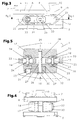
- a device 1 for fixing a dental model 2 (see FIG. 6) on the arms 2 and 3 an articulator 4 or on a processing arrangement consists of a mounting plate 5, which on each arm 2 or 3 of the articulator 4 or a corresponding processing arrangement can be fastened in the correct position and one at a distance from the mounting plate 5 provided support plate 6 for the dental model 2.
- adjusting and clamping devices which are still below are explained in more detail.
- the support plate 6 and the mounting plate 5 are conventional Aligned approximately parallel to each other, but can also be of parallelism enclose deviating angles. For optimal adjustment of the platen should here the possibility of creating the support plate in all directions is created can be tilted or swiveled in order to then be in the desired position To be able to fix inclination, vertical or horizontal position.
- each other fixed Abutment provided, for example, in the form of two cantilevered pins 7.
- This bar 9 forms a movable and adjustable with respect to the pins 7, the support plane 11 to outstanding abutment 10.
- Threaded bolt 12 is provided, which is rotatably but axially not displaceably mounted in the beam 9 is.
- the threaded bolt 12 engages in a threaded hole in the support plate 6, whereby Twisting the threaded bolt 12 of the beams 9 and thus the abutment 10 relative to the pins 7 is adjustable in order to clamp or release the dental model 2.
- the support plate 6 is adjustable relative to the mounting plate 5. Both are free cantilevered arms 13 and 14 are arranged on the mounting plate 5 and on the support plate 6, which are assigned coupling elements 15 on both sides. Furthermore, a pair of Support rails 16 and 17 are provided, the end regions corresponding to the coupling elements 15 are executed. The support rails 16 and 17 thus capture the ends Coupling elements 15, which are mounted on the projecting arms 13 and 14, respectively. The two Support rails 16 and 17 can be tightened against one another by means of a clamping device 18 and thus can be pressed against the coupling elements 15.
- the coupling elements 15 are as cap-shaped parts with in the contact area with the Support rails executed spherical segment-shaped surface 19.
- the two sides of each Arms 13 and 14 arranged on the mounting plate 5 and on the support plate 6 coupling elements 15 aligned on the arms 13 and 14 are aligned with each other.
- the coupling elements 15 project Pin 20, which in guide slots 21 and formed on the arms 13 and 14 22 intervene.
- the coupling elements 15 of each arm 13 and 14 are in synchronism with each other displaceable in the respective guide slot 21 or 22. Since the ends of the bolts 23, 24 not at the bottom of the bores 25, the coupling elements are practically axially displaceable held on the bolts 23, 24.
- both mutually assigned coupling elements can also be firmly attached to the Press on the surface of the arms 13 or 14.
- the clamping device 18 is designed as a clamping screw 26.
- This Clamping screw 26 is passed through a through hole 27 on one support rail 16 and engages with a threaded portion 28 in a threaded bore 29 of the other Support rail.
- the clamping screw 26 in the central region between is advantageous the two coupling elements 15, that is to say in the central region in relation to the length of the support rails 16 and 17 arranged. It would also be safe to arrange more than one clamping screw 26 conceivable, but then the construction becomes unnecessarily complicated, because with just one single clamping screw is also sufficient.
- clamping device Another design of the clamping device would be through various design measures conceivable. So it would be possible to use a clamping device like an eccentric to be provided, e.g. with a foldable lever, which on an eccentric clamping element attacks.
- the clamping device 18 is composed of a clamping screw 26 and one between the head 30 the clamping screw 26 and a support rail 16 inserted clamping lever 31 is formed.
- the Clamping lever 31 is on the one hand near the through hole 27 for the clamping screw 26, namely via a support foot 32, and on the other hand at an end region of the support rail 16, namely in Area of the coupling elements 15 assigned there, on the surface of the support rail 16 supported.
- the support area of the at the free end area of the clamping lever 31 is one formed in the clamping lever 31 rotatable screw 33.
- the clamping lever 31 extends from the central region of a support rail 16 or 17 toward an end portion thereof. It would also be within the scope of the invention conceivable that such support levers 31 would be assigned to both support rails 16 and 17, wherein because this starts from the middle area of the same to the two opposite end areas would bridge. Nevertheless, this would also be the case with a single clamping screw 26 or to create another clamping device. When a clamping screw 26 is arranged would then be a through hole 27 in one clamping lever and in the two support rails and then in the other clamping lever would be the threaded hole for engaging the threaded area the clamping screw.
- the support rails 16 and 17 in the contact area to the coupling elements 15 an annular, adapted to the spherical surface of the coupling elements 15 Have support surface 34.
- the support plate 6 on which the dental model 2 is like can be clamped with a vice or a screw clamp after loosening the clamping device 18 compared to the mounting plate 5 both in height and laterally and also is adjustable in the angular position, that is in various inclinations.
- the Device 1 according to the invention is generally used in pairs, as can also be seen in FIG. 6 can be.
- the device can also be used in other dental technology Processing arrangements can be used advantageously, e.g. in connection with split plates. It is also conceivable for a dental model 2 to be clamped onto a support plate 6 Way is transported from one processing arrangement to another, so that always the same Adjustment of the support plate 6 is given in relation to the mounting plate.
Landscapes
- Health & Medical Sciences (AREA)
- Oral & Maxillofacial Surgery (AREA)
- Dentistry (AREA)
- Epidemiology (AREA)
- Life Sciences & Earth Sciences (AREA)
- Animal Behavior & Ethology (AREA)
- General Health & Medical Sciences (AREA)
- Public Health (AREA)
- Veterinary Medicine (AREA)
- Dental Prosthetics (AREA)
- Dental Tools And Instruments Or Auxiliary Dental Instruments (AREA)
- Instructional Devices (AREA)
Abstract
Description
Claims (11)
- Vorrichtung zum Festlegen eines Dentalmodelles an den Armen eines Artikulators oder an einer Bearbeitungsanordnung mit einer Montageplatte, die am Arm des Artikulators oder einer Bearbeitungsanordnung positionsgerecht befestigbar ist und mit einer mit Abstand zur Montageplatte vorgesehenen Auflageplatte für das Dentalmodell und für die Befestigung desselben, wobei die Auflageplatte gegenüber der Montageplatte verstellbar ausgeführt ist, dadurch gekennzeichnet, dass sowohl an der Montageplatte (5) als auch an der Auflageplatte (6) frei auskragende Arme (13,14) mit beidseitig ausgebildeten Kupplungselementen (15) angeordnet sind und ein Paar von Stützschienen (16,17) mit ihren korrespondierend zu den Kupplungselementen (15) ausgeführten Enden die Kupplungselemente (15) an den auskragenden Armen (13,14) erfassen, und dass die beiden Stützschienen (16,17) mittels einer Klemmvorrichtung (18) gegeneinander anziehbar und somit an die Kupplungselemente (15) anpressbar sind.
- Vorrichtung nach Anspruch 1, dadurch gekennzeichnet, dass die Kupplungselemente (15) als kappenförmige Teile mit im Berührungsbereich mit den Stützschienen (16,17) kugelabschnittförmiger Oberfläche (19) ausgeführt sind, wobei beidseitig der jeweiligen Arme (13,14) an der Montageplatte (5) und an der Auflageplatte (6) angeordnete Kupplungselemente (15) achsgleich zueinander ausgerichtet an den Armen (13,14) gehalten sind.
- Vorrichtung nach den Ansprüchen 1 und 2, dadurch gekennzeichnet, dass die Kupplungselemente (15) der kugelabschnittförmigen Oberfläche (19) abgewandt vorstehende Zapfen (20) aufweisen, welche in einen an den Armen (13,14) ausgebildeten Führungsschlitz (21,22) eingreifen und dass die beidseitig eines jeden Armes (13,14) angeordneten Kupplungselemente (15) über einen in im Zentrum der vorstehenden Zapfen (20) ausgebildete Bohrungen (25) eingreifenden Bolzen (23) gleichlaufend miteinander im Führungsschlitz (21,22) verschiebbar sind.
- Vorrichtung nach Anspruch 3, dadurch gekennzeichnet, dass die Kupplungselemente (15) axial verschiebbar an den Bolzen (23) geführt gehalten sind.
- Vorrichtung nach Anspruch 1 und einem der vorstehenden Ansprüche, dadurch gekennzeichnet, dass die den frei auskragenden Armen (13,14) zugewandten Auflageflächen der Kupplungselemente (15) eine umlaufende Ringnut aufweisen, so dass nur der dem Aussenumfang nahe ringförmige Bereich an der Oberfläche der Arme (13,14) abgestützt ist.
- Vorrichtung nach Anspruch 1, dadurch gekennzeichnet, dass die Klemmvorrichtung (18) als Klemmschraube (26) ausgebildet ist, welche in einer Durchgangsbohrung (27) der einen Stützschiene (16) hindurchgeführt ist und mit einem Gewindeabschnitt (28) in eine Gewindebohrung (29) der anderen Stützschiene (17) eingreift.
- Vorrichtung nach Anspruch 6, dadurch gekennzeichnet, dass die Klemmschraube (26) im Mittelbereich zwischen den beiden Kupplungselementen (15), also im Mittelbereich bezogen auf die Länge der Stützschienen (16,17), angeordnet ist.
- Vorrichtung nach den Ansprüchen 1 oder 2 und 3, dadurch gekennzeichnet, dass die Klemmvorrichtung (18) aus einer Klemmschraube (26) und einem zwischen den Kopf (30) der Klemmschraube (26) und eine Stützschiene (16) eingesetzten Klemmhebel (31) gebildet ist, wobei sich der Klemmhebel (31) einerseits nahe dem Durchgangsloch (27) für die Klemmschraube (26) und andererseits an einem Endbereich der Stützschiene (16), und zwar im Bereich der dort zugeordneten Kupplungselemente (15), an der Oberfläche der Stützschiene (16) abgestützt ist.
- Vorrichtung nach Anspruch 9, dadurch gekennzeichnet, dass zumindest einer der Abstützbereiche des Klemmhebels (31) vom freien Ende einer im Klemmhebel (31) verdrehbaren Stellschraube (33) gebildet ist.
- Vorrichtung nach den Ansprüchen 8 und 9, dadurch gekennzeichnet, dass der Klemmhebel (31) sich vom Mittelbereich einer Stützschiene (16,17) in Richtung zu einem Endbereich derselben erstreckt.
- Vorrichtung nach Anspruch 1, dadurch gekennzeichnet, dass die Stützschienen (16,17) im Anlagebereich zu den Kupplungselementen (15) eine ringförmige, der Kugeloberfläche derselben angepasste Abstützfläche (34) aufweisen.
Applications Claiming Priority (2)
| Application Number | Priority Date | Filing Date | Title |
|---|---|---|---|
| DE29919330U | 1999-11-03 | ||
| DE29919330U DE29919330U1 (de) | 1999-11-03 | 1999-11-03 | Vorrichtung zum Festlegen eines Dentalmodells an den Armen eines Artikulators |
Publications (3)
| Publication Number | Publication Date |
|---|---|
| EP1097677A2 true EP1097677A2 (de) | 2001-05-09 |
| EP1097677A3 EP1097677A3 (de) | 2003-01-02 |
| EP1097677B1 EP1097677B1 (de) | 2006-01-18 |
Family
ID=8081137
Family Applications (1)
| Application Number | Title | Priority Date | Filing Date |
|---|---|---|---|
| EP00123875A Expired - Lifetime EP1097677B1 (de) | 1999-11-03 | 2000-11-02 | Vorrichtung zum Festlegen eines Dentalmodelles an den Armen eines Artikulators |
Country Status (3)
| Country | Link |
|---|---|
| EP (1) | EP1097677B1 (de) |
| AT (1) | ATE315913T1 (de) |
| DE (2) | DE29919330U1 (de) |
Citations (2)
| Publication number | Priority date | Publication date | Assignee | Title |
|---|---|---|---|---|
| AT393077B (de) | 1990-01-22 | 1991-08-12 | Amann Dietmar | Artikulator |
| AT400098B (de) | 1993-10-22 | 1995-09-25 | Dietmar Amann | Vorrichtung zum festlegen eines dentalmodelles an den armen eines artikulators |
Family Cites Families (4)
| Publication number | Priority date | Publication date | Assignee | Title |
|---|---|---|---|---|
| US2801470A (en) * | 1955-08-19 | 1957-08-06 | Donald G Logan | Dental articulator attachment |
| FR2354085A1 (fr) * | 1976-06-11 | 1978-01-06 | Ouaknine Gilbert | Occluseur dentaire |
| US4402670A (en) * | 1981-08-24 | 1983-09-06 | Lee Tsung Li | Three-dimensionally adjustable supporting and locking mechanism |
| DE9115679U1 (de) * | 1991-12-18 | 1992-02-20 | Kiefer, Wilhelm H., 7520 Bruchsal | Verstellbare Sockelplattenhalterung für einen Artikulator |
-
1999
- 1999-11-03 DE DE29919330U patent/DE29919330U1/de not_active Expired - Lifetime
-
2000
- 2000-11-02 DE DE50012073T patent/DE50012073D1/de not_active Expired - Lifetime
- 2000-11-02 AT AT00123875T patent/ATE315913T1/de not_active IP Right Cessation
- 2000-11-02 EP EP00123875A patent/EP1097677B1/de not_active Expired - Lifetime
Patent Citations (2)
| Publication number | Priority date | Publication date | Assignee | Title |
|---|---|---|---|---|
| AT393077B (de) | 1990-01-22 | 1991-08-12 | Amann Dietmar | Artikulator |
| AT400098B (de) | 1993-10-22 | 1995-09-25 | Dietmar Amann | Vorrichtung zum festlegen eines dentalmodelles an den armen eines artikulators |
Also Published As
| Publication number | Publication date |
|---|---|
| EP1097677B1 (de) | 2006-01-18 |
| EP1097677A3 (de) | 2003-01-02 |
| ATE315913T1 (de) | 2006-02-15 |
| DE50012073D1 (de) | 2006-04-06 |
| DE29919330U1 (de) | 2001-03-15 |
Similar Documents
| Publication | Publication Date | Title |
|---|---|---|
| EP0369197B1 (de) | Klammer zum Verbinden von Schaltafeln | |
| DE69512489T2 (de) | Gelenkelement für äussere Fixationskomponenten | |
| AT391162B (de) | Scharnier | |
| EP0847255A1 (de) | Anker für implantatkörper und richtvorrichtung zu deren ausrichtung | |
| EP0635286A1 (de) | Gleitbrett | |
| EP2345507A2 (de) | Vorrichtung zum Klemmen von Werkstücken auf einer Basis | |
| DE2359490C3 (de) | Vorderer Bindungsteil einer Sicherheitsbindung fur Ski | |
| AT393797B (de) | Bindung fuer snowboards | |
| DE4211020C2 (de) | Zahnärztlicher Artikulator | |
| EP3613912A1 (de) | Modularer bausatz sowie anbauteil zum aufbau von dreidimensionalen strukturen für die positionsfeste aufnahme von werkstücken | |
| EP1097677B1 (de) | Vorrichtung zum Festlegen eines Dentalmodelles an den Armen eines Artikulators | |
| DE29803775U1 (de) | Schußwaffenschaft | |
| CH682883A5 (de) | Einrichtung zur Bildung eines Scharnieres für Kieferkorrekturen. | |
| EP0394380A1 (de) | Sicherheitsskibindung. | |
| DE102013209277A1 (de) | Zehenhalter mit Einsteighilfe | |
| DE3036109C2 (de) | Artikulator für gnathologische Zwecke | |
| DE2462548C3 (de) | Vorderbacken für Sicherheitsskibindungen | |
| DE9202987U1 (de) | Sicherheitsbindung für Snowboards | |
| DE4207143C1 (de) | Sicherheitsbindung für Snowboards | |
| DE3719248C2 (de) | ||
| DE19953827A1 (de) | Vorrichtung zum Regulieren der Zähne | |
| AT393077B (de) | Artikulator | |
| DE69411663T2 (de) | Seitliche Webrahmenführungsvorrichtung mit Verriegel- und Entriegelungsvorrichtung | |
| DE19828211A1 (de) | Spannbacken zum Spannen eines Werkstücks auf dem Tisch einer Werkzeugmaschine | |
| DE3722883C1 (en) | Device for occlusal correction |
Legal Events
| Date | Code | Title | Description |
|---|---|---|---|
| PUAI | Public reference made under article 153(3) epc to a published international application that has entered the european phase |
Free format text: ORIGINAL CODE: 0009012 |
|
| AK | Designated contracting states |
Kind code of ref document: A2 Designated state(s): AT BE CH CY DE DK ES FI FR GB GR IE IT LI LU MC NL PT SE TR |
|
| AX | Request for extension of the european patent |
Free format text: AL;LT;LV;MK;RO;SI |
|
| PUAL | Search report despatched |
Free format text: ORIGINAL CODE: 0009013 |
|
| AK | Designated contracting states |
Kind code of ref document: A3 Designated state(s): AT BE CH CY DE DK ES FI FR GB GR IE IT LI LU MC NL PT SE TR |
|
| AX | Request for extension of the european patent |
Free format text: AL;LT;LV;MK;RO;SI |
|
| 17P | Request for examination filed |
Effective date: 20030603 |
|
| AKX | Designation fees paid |
Designated state(s): AT BE CH CY DE DK ES FI FR GB GR IE IT LI LU MC NL PT SE TR |
|
| 17Q | First examination report despatched |
Effective date: 20041006 |
|
| GRAP | Despatch of communication of intention to grant a patent |
Free format text: ORIGINAL CODE: EPIDOSNIGR1 |
|
| GRAS | Grant fee paid |
Free format text: ORIGINAL CODE: EPIDOSNIGR3 |
|
| GRAA | (expected) grant |
Free format text: ORIGINAL CODE: 0009210 |
|
| AK | Designated contracting states |
Kind code of ref document: B1 Designated state(s): AT BE CH CY DE DK ES FI FR GB GR IE IT LI LU MC NL PT SE TR |
|
| PG25 | Lapsed in a contracting state [announced via postgrant information from national office to epo] |
Ref country code: IT Free format text: LAPSE BECAUSE OF FAILURE TO SUBMIT A TRANSLATION OF THE DESCRIPTION OR TO PAY THE FEE WITHIN THE PRESCRIBED TIME-LIMIT;WARNING: LAPSES OF ITALIAN PATENTS WITH EFFECTIVE DATE BEFORE 2007 MAY HAVE OCCURRED AT ANY TIME BEFORE 2007. THE CORRECT EFFECTIVE DATE MAY BE DIFFERENT FROM THE ONE RECORDED. Effective date: 20060118 Ref country code: FI Free format text: LAPSE BECAUSE OF FAILURE TO SUBMIT A TRANSLATION OF THE DESCRIPTION OR TO PAY THE FEE WITHIN THE PRESCRIBED TIME-LIMIT Effective date: 20060118 Ref country code: GB Free format text: LAPSE BECAUSE OF FAILURE TO SUBMIT A TRANSLATION OF THE DESCRIPTION OR TO PAY THE FEE WITHIN THE PRESCRIBED TIME-LIMIT Effective date: 20060118 Ref country code: IE Free format text: LAPSE BECAUSE OF FAILURE TO SUBMIT A TRANSLATION OF THE DESCRIPTION OR TO PAY THE FEE WITHIN THE PRESCRIBED TIME-LIMIT Effective date: 20060118 Ref country code: NL Free format text: LAPSE BECAUSE OF FAILURE TO SUBMIT A TRANSLATION OF THE DESCRIPTION OR TO PAY THE FEE WITHIN THE PRESCRIBED TIME-LIMIT Effective date: 20060118 |
|
| REG | Reference to a national code |
Ref country code: GB Ref legal event code: FG4D Free format text: NOT ENGLISH |
|
| REG | Reference to a national code |
Ref country code: CH Ref legal event code: EP |
|
| REG | Reference to a national code |
Ref country code: IE Ref legal event code: FG4D Free format text: LANGUAGE OF EP DOCUMENT: GERMAN |
|
| REF | Corresponds to: |
Ref document number: 50012073 Country of ref document: DE Date of ref document: 20060406 Kind code of ref document: P |
|
| PG25 | Lapsed in a contracting state [announced via postgrant information from national office to epo] |
Ref country code: SE Free format text: LAPSE BECAUSE OF FAILURE TO SUBMIT A TRANSLATION OF THE DESCRIPTION OR TO PAY THE FEE WITHIN THE PRESCRIBED TIME-LIMIT Effective date: 20060418 Ref country code: DK Free format text: LAPSE BECAUSE OF FAILURE TO SUBMIT A TRANSLATION OF THE DESCRIPTION OR TO PAY THE FEE WITHIN THE PRESCRIBED TIME-LIMIT Effective date: 20060418 |
|
| PG25 | Lapsed in a contracting state [announced via postgrant information from national office to epo] |
Ref country code: ES Free format text: LAPSE BECAUSE OF FAILURE TO SUBMIT A TRANSLATION OF THE DESCRIPTION OR TO PAY THE FEE WITHIN THE PRESCRIBED TIME-LIMIT Effective date: 20060429 |
|
| PG25 | Lapsed in a contracting state [announced via postgrant information from national office to epo] |
Ref country code: PT Free format text: LAPSE BECAUSE OF FAILURE TO SUBMIT A TRANSLATION OF THE DESCRIPTION OR TO PAY THE FEE WITHIN THE PRESCRIBED TIME-LIMIT Effective date: 20060619 |
|
| NLV1 | Nl: lapsed or annulled due to failure to fulfill the requirements of art. 29p and 29m of the patents act | ||
| GBV | Gb: ep patent (uk) treated as always having been void in accordance with gb section 77(7)/1977 [no translation filed] |
Effective date: 20060118 |
|
| REG | Reference to a national code |
Ref country code: IE Ref legal event code: FD4D |
|
| PLBE | No opposition filed within time limit |
Free format text: ORIGINAL CODE: 0009261 |
|
| STAA | Information on the status of an ep patent application or granted ep patent |
Free format text: STATUS: NO OPPOSITION FILED WITHIN TIME LIMIT |
|
| PG25 | Lapsed in a contracting state [announced via postgrant information from national office to epo] |
Ref country code: BE Free format text: LAPSE BECAUSE OF NON-PAYMENT OF DUE FEES Effective date: 20061130 Ref country code: LI Free format text: LAPSE BECAUSE OF NON-PAYMENT OF DUE FEES Effective date: 20061130 Ref country code: CH Free format text: LAPSE BECAUSE OF NON-PAYMENT OF DUE FEES Effective date: 20061130 Ref country code: MC Free format text: LAPSE BECAUSE OF NON-PAYMENT OF DUE FEES Effective date: 20061130 |
|
| 26N | No opposition filed |
Effective date: 20061019 |
|
| EN | Fr: translation not filed | ||
| REG | Reference to a national code |
Ref country code: CH Ref legal event code: PL |
|
| PGFP | Annual fee paid to national office [announced via postgrant information from national office to epo] |
Ref country code: AT Payment date: 20070706 Year of fee payment: 7 |
|
| BERE | Be: lapsed |
Owner name: AMANN, DIETMAR Effective date: 20061130 |
|
| PG25 | Lapsed in a contracting state [announced via postgrant information from national office to epo] |
Ref country code: FR Free format text: LAPSE BECAUSE OF FAILURE TO SUBMIT A TRANSLATION OF THE DESCRIPTION OR TO PAY THE FEE WITHIN THE PRESCRIBED TIME-LIMIT Effective date: 20070309 Ref country code: GR Free format text: LAPSE BECAUSE OF FAILURE TO SUBMIT A TRANSLATION OF THE DESCRIPTION OR TO PAY THE FEE WITHIN THE PRESCRIBED TIME-LIMIT Effective date: 20060419 |
|
| PG25 | Lapsed in a contracting state [announced via postgrant information from national office to epo] |
Ref country code: TR Free format text: LAPSE BECAUSE OF FAILURE TO SUBMIT A TRANSLATION OF THE DESCRIPTION OR TO PAY THE FEE WITHIN THE PRESCRIBED TIME-LIMIT Effective date: 20060118 Ref country code: LU Free format text: LAPSE BECAUSE OF NON-PAYMENT OF DUE FEES Effective date: 20061102 |
|
| PG25 | Lapsed in a contracting state [announced via postgrant information from national office to epo] |
Ref country code: AT Free format text: LAPSE BECAUSE OF NON-PAYMENT OF DUE FEES Effective date: 20071102 |
|
| PG25 | Lapsed in a contracting state [announced via postgrant information from national office to epo] |
Ref country code: CY Free format text: LAPSE BECAUSE OF FAILURE TO SUBMIT A TRANSLATION OF THE DESCRIPTION OR TO PAY THE FEE WITHIN THE PRESCRIBED TIME-LIMIT Effective date: 20060118 Ref country code: FR Free format text: LAPSE BECAUSE OF FAILURE TO SUBMIT A TRANSLATION OF THE DESCRIPTION OR TO PAY THE FEE WITHIN THE PRESCRIBED TIME-LIMIT Effective date: 20060118 |
|
| REG | Reference to a national code |
Ref country code: DE Ref legal event code: R082 Ref document number: 50012073 Country of ref document: DE Representative=s name: SCHUMACHER & WILLSAU PATENTANWALTSGESELLSCHAFT, DE |
|
| PGFP | Annual fee paid to national office [announced via postgrant information from national office to epo] |
Ref country code: DE Payment date: 20200130 Year of fee payment: 20 |
|
| REG | Reference to a national code |
Ref country code: DE Ref legal event code: R071 Ref document number: 50012073 Country of ref document: DE |