EP1097760A2 - Metallrohraufweiter - Google Patents
Metallrohraufweiter Download PDFInfo
- Publication number
- EP1097760A2 EP1097760A2 EP00124427A EP00124427A EP1097760A2 EP 1097760 A2 EP1097760 A2 EP 1097760A2 EP 00124427 A EP00124427 A EP 00124427A EP 00124427 A EP00124427 A EP 00124427A EP 1097760 A2 EP1097760 A2 EP 1097760A2
- Authority
- EP
- European Patent Office
- Prior art keywords
- metal pipe
- expanded
- section
- pressure receiving
- expanding
- Prior art date
- Legal status (The legal status is an assumption and is not a legal conclusion. Google has not performed a legal analysis and makes no representation as to the accuracy of the status listed.)
- Withdrawn
Links
- 239000002184 metal Substances 0.000 title claims abstract description 198
- 239000007788 liquid Substances 0.000 claims abstract description 34
- 238000010791 quenching Methods 0.000 claims description 2
- 230000000171 quenching effect Effects 0.000 claims description 2
- 238000004381 surface treatment Methods 0.000 claims description 2
- 238000005452 bending Methods 0.000 description 22
- 229910000831 Steel Inorganic materials 0.000 description 9
- 239000010959 steel Substances 0.000 description 9
- XLYOFNOQVPJJNP-UHFFFAOYSA-N water Substances O XLYOFNOQVPJJNP-UHFFFAOYSA-N 0.000 description 9
- 239000003129 oil well Substances 0.000 description 7
- 238000007789 sealing Methods 0.000 description 6
- 238000000034 method Methods 0.000 description 5
- 238000010276 construction Methods 0.000 description 4
- 238000002474 experimental method Methods 0.000 description 3
- 239000000463 material Substances 0.000 description 3
- 230000000903 blocking effect Effects 0.000 description 2
- -1 e.g. Substances 0.000 description 2
- 239000004033 plastic Substances 0.000 description 2
- 239000000956 alloy Substances 0.000 description 1
- 229910045601 alloy Inorganic materials 0.000 description 1
- 230000009172 bursting Effects 0.000 description 1
- 239000000919 ceramic Substances 0.000 description 1
- 230000000052 comparative effect Effects 0.000 description 1
- 238000007796 conventional method Methods 0.000 description 1
- 238000009792 diffusion process Methods 0.000 description 1
- 230000000694 effects Effects 0.000 description 1
- 230000005489 elastic deformation Effects 0.000 description 1
- 239000013013 elastic material Substances 0.000 description 1
- 239000007791 liquid phase Substances 0.000 description 1
- 239000000314 lubricant Substances 0.000 description 1
- 229910052982 molybdenum disulfide Inorganic materials 0.000 description 1
- 239000006223 plastic coating Substances 0.000 description 1
- 230000002265 prevention Effects 0.000 description 1
- 235000015096 spirit Nutrition 0.000 description 1
- 239000000126 substance Substances 0.000 description 1
Images

Classifications
-
- E—FIXED CONSTRUCTIONS
- E21—EARTH OR ROCK DRILLING; MINING
- E21B—EARTH OR ROCK DRILLING; OBTAINING OIL, GAS, WATER, SOLUBLE OR MELTABLE MATERIALS OR A SLURRY OF MINERALS FROM WELLS
- E21B43/00—Methods or apparatus for obtaining oil, gas, water, soluble or meltable materials or a slurry of minerals from wells
- E21B43/02—Subsoil filtering
- E21B43/10—Setting of casings, screens, liners or the like in wells
- E21B43/103—Setting of casings, screens, liners or the like in wells of expandable casings, screens, liners, or the like
- E21B43/105—Expanding tools specially adapted therefor
-
- B—PERFORMING OPERATIONS; TRANSPORTING
- B21—MECHANICAL METAL-WORKING WITHOUT ESSENTIALLY REMOVING MATERIAL; PUNCHING METAL
- B21D—WORKING OR PROCESSING OF SHEET METAL OR METAL TUBES, RODS OR PROFILES WITHOUT ESSENTIALLY REMOVING MATERIAL; PUNCHING METAL
- B21D31/00—Other methods for working sheet metal, metal tubes, metal profiles
- B21D31/04—Expanding other than provided for in groups B21D1/00 - B21D28/00, e.g. for making expanded metal
-
- E—FIXED CONSTRUCTIONS
- E21—EARTH OR ROCK DRILLING; MINING
- E21B—EARTH OR ROCK DRILLING; OBTAINING OIL, GAS, WATER, SOLUBLE OR MELTABLE MATERIALS OR A SLURRY OF MINERALS FROM WELLS
- E21B23/00—Apparatus for displacing, setting, locking, releasing or removing tools, packers or the like in boreholes or wells
- E21B23/08—Introducing or running tools by fluid pressure, e.g. through-the-flow-line tool systems
- E21B23/10—Tools specially adapted therefor
-
- Y—GENERAL TAGGING OF NEW TECHNOLOGICAL DEVELOPMENTS; GENERAL TAGGING OF CROSS-SECTIONAL TECHNOLOGIES SPANNING OVER SEVERAL SECTIONS OF THE IPC; TECHNICAL SUBJECTS COVERED BY FORMER USPC CROSS-REFERENCE ART COLLECTIONS [XRACs] AND DIGESTS
- Y10—TECHNICAL SUBJECTS COVERED BY FORMER USPC
- Y10T—TECHNICAL SUBJECTS COVERED BY FORMER US CLASSIFICATION
- Y10T29/00—Metal working
- Y10T29/49—Method of mechanical manufacture
- Y10T29/49718—Repairing
Definitions
- the present invention relates to a metal pipe expander for uniformly expanding a metal pipe in its inner diameter.
- the pipe expanding method does not function well in expanding a long metal pipe, e.g., an oil well pipe extending several hundreds meters to several kilometers.
- the shaft for driving forward the metal pipe expander suddenly buckles.
- the expanding method it is remotely possible to employ the expanding method.
- the following pipe expanding method is used. Liquid, e.g., water, after pressurized, is supplied into the metal pipe. A liquid pressure generated is applied to the rear end face of the metal pipe expander, and the propel force caused by the liquid pressure drives forward the metal pipe expander, thereby expanding the steel pipe in diameter.
- the liquid-pressure basis expanding method has also the following serious problem.
- the metal pipe is often broken (burst) at a position near the metal pipe expander located by the liquid pressure for driving forward the metal pipe expander.
- the bursting accident occurs at a deep place in the earth, it is impossible to repair the broken, long oil-well pipe unless it is dug out of the ground. This presents a serious problem.
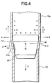
- a metal pipe expander 41 shaped like a conic body, is inserted into a metal pipe 10, and moved forward (in the direction of an arrow X) for pipe expansion by a liquid pressure.
- an expanding force F acts on an expanded part 13 of the metal pipe 10, which is under deformation by the press fitting of the a conical surface 41a of the metal pipe expander 41.
- an expanded portion 10a of the metal pipe receives a tension T which has a direction coincident with a longitudinal direction of the pipe and corresponds to the propel force of the metal pipe expander 41, and an internal force R which results from a liquid pressure "p" causing the propel force.
- Those three forces act on an expansion-terminating position 14 of the pipe and therearound in a complex manner. As a result, excessive stress is generated and the pipe is easy to be broken thereat. This fact was found and confirmed by the inventor. Further, the inventor carefully examined the metal pipes broken when those pipes were expanded. From the examination, it was found that many broken pipes were broken while being greatly bent.
- the present invention was made based on the findings mentioned above, and prevents excessive stress from acting on the metal pipe by blocking the exerting of the internal force R on the expansion-terminating position 14 and therearound or by the internal force blocking and by restricting the bending of the metal pipe associated with the pipe expanding operation.
- a first metal pipe expander which is inserted into a metal pipe and driven to move in the axial direction of the metal pipe by a liquid pressure, wherein a cup shaped portion opened to the rear side, the outer surface of which is in slide contact with the inner surface of the metal pipe after it is expanded in diameter, is provided at the rear end of an expanding section with a conical portion of which the small diameter portion is directed to the front side.
- the term "fore” side means the fore side as viewed in a direction in which the metal pipe expander advances when the pipe is expanded.
- the term “rear” side means the side opposite to the fore side.
- a liquid pressure of pressurized liquid supplied into the metal pipe acts on the rear end of a cup shaped portion of the pressure receiving section of the metal pipe expander, to thereby drive and move forward the expanding section integral with the pressure receiving section to expand the metal pipe.
- the liquid pressure is sealed with a sliding contact portion between the outer surface of the cup shaped portion and the inner surface of the expanded metal pipe. Therefore, there is no chance that an internal force R caused by the liquid pressure acts on the inner surface of the metal pipe located on the fore side. Accordingly, the internal force R does not exert-on the expansion-terminating position and therearound of the metal pipe. As a consequence, an excessive stress is not generated in the metal pipe.
- One pressure receiving section may be used for the pressure receiving section located on the rear side of the expanding section.
- a plurality of the pressure receiving sections may be provided while being longitudinally and contiguously arranged as in the second metal pipe expander.
- the sealing of the outer surface of the cup shaped portion of the pressure receiving section located on the fore side reliably blocks application of the internal force R to the expansion-terminating position 14 and its near portion of the expanded metal pipe.
- the construction of the second metal pipe expander is preferable.
- the metal pipe is supported at a total of three locations linearly arrayed, the expanding section and the plurality of cup shaped portions of the pressure receiving sections. Therefore, the bending of the metal pipe caused when the pipe is expanded is controlled to be extremely small. As a result, the breakage of the metal pipe owing to this bending is reliably prevented. In this respect, the construction of the second metal pipe expander is more preferable.
- the metal pipe in which a guide portion is further provided between the expanding section and the pressure receiving section in a state that the guide portion is in slide contact with the inner surface of the metal pipe after it is expanded, during and after the pipe expanding operation, the metal pipe is supported at a total of at least three locations, the expanding section and one or the plurality (in the case of the second metal pipe expander) of cup shaped portions. Therefore, the bending of the metal pipe caused when the pipe is expanded is controlled to be extremely small. As a result, the breakage of the metal pipe owing to this bending is reliably prevented. In this respect, the construction of the third metal pipe expander is preferable.
- the fitting part of the guide portion is brought into press contact with the inner surface of the metal pipe before it is not yet expanded, so that an inclination of the axial line of the expanding section with respect to the axial line of the metal pipe not yet expanded is controlled to be extremely small.
- This technical feature also reduces the bending of the metal pipe by the pipe expansion, and prevents the breakage of the metal pipe owing to this bending.
- the construction of the fourth metal pipe expander is preferable.
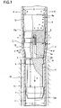
- reference numeral 1 designates a metal pipe expander for expanding a metal pipe 10 as an oil well pipe in diameter.
- a pressure receiving section 3 is contiguous to the rear side of the expanding section 2.
- a guide section 4 is contiguous to the fore side of the expanding section 2.
- the expanding section 2 made of steel includes a conical portion 5 of the vertical angle of 2a, of which the small diameter side is located on the fore side of the expanding section.
- a conical surface 5a of the conical portion is hardened by quenching.
- the pressure receiving section 3 is made of steel having an elasticity, and includes a cup shaped portion 6 opened to the rear side.
- a rear end 6a of the cup shaped portion 6, which gradually increases its diameter toward the rear side, has an outer diameter which is equal to or somewhat (e.g., 0 to 0.5mm) smaller than the diameter of the large diameter side of the conical portion 5 so that it slidably contacts with an inner surface 12 of the expanded portion 10a of the metal pipe 10 (Note: a portion of the metal pipe 10 through which the conical portion 5 passed reduces its diameter because of its elastic deformation, and therefore if the outer diameter of the rear end of the cup shaped portion is so selected, the slidable contact of the rear end with the inner surface is ensured.).
- a thickness "t" of the cup shaped portion 6 is thinner than that of the expanded portion 10a. If so selected, the cup shaped portion 6 is elastically deformed by the liquid pressure, so that it is easy to be in press contact with the inner surface 12.
- the outer surface of the cup shaped portion 6, which comes in slide contact with the inner surface 12, is preferably subjected to a surface treatment (e.g., plastic coating) in order to secure a wear proofthereof.
- a strip-like ring made of ceramics or plastic may be fit to the outer surface of the cup shaped portion.
- the entire of the pressure receiving section 3 or the cup shaped portion 6 thereof may be made of elastic material, e.g., rubber, other than metal.
- the guide section 4 is made of steel and provided with a fitting head 7.
- the fitting head 7 is located in front of the expanding section 2, and will be fit into the metal pipe in a state that a slight gap (e.g., 1 to 2mm at one side) is present between it and the inner surface 11 of the metal pipe 10 before it is expanded.
- the guide section 4 is shaped like a cylindrical rod with a step.
- a threaded bar 8 while being integral with the guide section 4, is extended from the rear end of the guide section.
- the threaded bar 8 of the guide section is passed through a center hole of the expanding section 2 and screwed into a threaded hole formed in the pressure receiving section 3, whereby those component parts are coupled together.
- a distance S of the fitting head 7 measured from the expanding section 2 (exactly the conical portion 5) of the fitting head 7 is selected to preferably be 1.5 times or more as long as the inner diameter "d" of the metal pipe 10. If the former is selected to be less than 1.5 times as long as the latter, the control of an inclination of the axial line of the expanding section 2, which will be described later, could be unsatisfactory.
- Reference numeral 9 designates a second fitting portion, which is provided at a position closer to the expanding section 2 whenever occasion calls. It is fit into the metal pipe 10 in a state that a slight gap is present between it and the inner surface 11 of the metal pipe.
- the thus constructed metal pipe expander 1 is used for expanding the metal pipe 10 in diameter in a manner that it is inserted into the metal pipe 10, and then a liquid pressure is applied to the rear side of the metal pipe expander.
- the metal pipe 10 is an oil well pipe and a casing is formed along a well bore 15 by the expanding the pipe.
- a long metal pipe 10 is formed in a manner that the end faces of a number of steel pipes are butted and an insert material is interposed between the end faces to be bonded, and the butted portion is bonded by the liquid phase diffusion process.
- the inner surface of the thus formed metal pipe 10 is coated with lubricant such as oil or MOS 2 , upon occasion.
- the resultant is inserted into and set in the well bore 15.
- the metal pipe expander 1 is inserted into an expanded portion (not shown) formed in advance at the foremost end of the metal pipe 10 in a state that the guide section 4 thereof is directed downward.
- the upper end of the expanded portion is closed with a cover or the like.
- a liquid pressure water pressure
- the metal pipe expander 1 is hydraulically driven to expand the metal pipe in diameter.
- the metal pipe expander 1 moves forward (descends) in the direction of an arrow X within the metal pipe 10 by the hydraulic pressure.
- the fitting head 7 of the guide section 4 which moves ahead, is fit into the metal pipe 10 before it is expanded and brought into contact with the inner surface 11 thereof. Therefore, an inclination of the axial line 2a of the expanding section 2 with respect to the axial line 10b of the metal pipe 10 is controlled to be extremely small.
- the metal pipe is expanded substantially uniformly expanded along the circumference thereof. As a result, bending of the metal that will be caused after it is expanded is controlled to be extremely small.
- a liquid pressure "p" acting on the rear end of the pressure receiving section 3 drives the metal pipe expander 1 to move forward.
- the conical portion 5 of the expanding section 2 forcibly moves forward within and along the metal pipe 10 to expand the metal pipe 10 in diameter such that the diameter "d" of the metal pipe 10 is increased to the diameter D.
- an expanding force F for the expanding (plastic deformation) vertically acts on the conical surface 5a at the expanded part 13 of the metal pipe 10
- a tension T corresponding to the propel force by the liquid pressure acts on the expanded portion 10a of the expanded metal pipe, which is located on the rear side of the expanded part 13 (on the upper side in the case of the oil well pipe).
- the rear end 6a of the cup shaped portion 6 is in a slide contact with the inner surface 12 of the expanded portion lOa of the metal pipe.
- a rear end part of the cup shaped portion 6 is elastically deformed by the liquid pressure P to be brought into press contact with the inner surface 12. Accordingly, the liquid pressure "p" is blocked with the inner surface 12 and the outer surface of the cup shaped portion 6.
- the internal force R acts only on the expanded portion 10a, which is located closer to the rear side (upper side) than the cup shaped portion 6, in the radially expanding direction.
- the internal force R does not act on the expansion-terminating position 14 and therearound in the expanded part 13 of the metal pipe 10.
- a force acting on the expansion-terminating position 14 and its vicinity is reduced by the internal force R when comparing with that in the case shown in Fig. 2. For this reason, the metal pipe 10 is prevented from being broken.
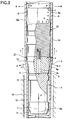
- Fig. 2 shows second embodiment of the present invention.
- like or equivalent portions are designated by like reference numerals in Fig. 1 (The same thing is correspondingly applied to other embodiment descriptions to follow.).
- a pressure receiving section 23 which is the same in structure as the pressure receiving section 3 except that its leg 23a is long, is contiguous to the rear side of the pressure receiving section 3.
- the remaining structure of the metal pipe expander 21 is the same as of the metal pipe expander 1 of the first embodiment as described above.
- a couple of the pressure receiving sections 3 and 23, which are longitudinally and contiguously arranged, are disposed on the rear side of the expanding section 2.
- a threaded bar 8 projected from the guide section 4 is passed through the center of the expanding section 2 and the pressure receiving section 3, and screwed into a threaded hole formed in the pressure receiving section 23, whereby those component parts are coupled into a single unit.
- the metal pipe expander 21 is inserted into the metal pipe 10, and a liquid pressure "p" is applied to the rear side of the metal pipe expander. Then, the liquid pressure "p" acting on the rear end of the pressure receiving section 23 propels the metal pipe expander 1, and the expanding section 2 expands the metal pipe 10 in diameter. At this time, the internal force R acts only the expanded portion 10a located closer to the rear side than the cup shaped portion 6, and an amount of inclination of the expanding section 2 is lessened to be small by the guide section 4. Those points are the same as in the first embodiment.
- the pressure receiving sections 3 and 23 are longitudinally arranged in a contiguous fashion. Therefore, even if, by wear of the outer surface of the cup shaped portion 6 of the pressure receiving section 23 and the like, sealing between it and the inner surface of the metal pipe is damaged, the sealing of the outer surface of the cup shaped portion 6 of the pressure receiving section 3 located on the fore side, which slidably contacts with the inner surface 12 of the expanded portion 10a of the metal pipe, blocks application of the internal force R to the expansion-terminating position 14 and its near portion of the metal pipe 10. Accordingly, the breakage of the metal pipe 10 is reliably prevented.
- the metal pipe 10 is supported at a total of three locations linearly arrayed, the expanding section 2 and the cup shaped portions 6 and 6 of the pressure receiving sections 3 and 23. Therefore, the bending of the metal pipe 10 caused when the pipe is expanded, for example, by the deviation of the wall thickness of the metal pipe is controlled to be extremely small. As a result, there never occurs such an unwanted situation that the stress caused by the bending excessively grows and eventually the metal pipe 10 will be broken.
- Fig. 3 shows a third embodiment of the present invention.
- a guide portion 34 which is in sliding contact with the inner surface of the metal pipe 10, is characteristically provided at a mid position of a long pressure receiving section 33 having a cup shaped portion 6 at the rear end.
- the remaining structure of the metal pipe expander is the same as of the metal pipe expander 1 of the first embodiment as described above.
- the guide portion 34 like the rear end 6a of the cup shaped portion 6, has the outer diameter equal to or somewhat (e.g., 0 to 05.mm) smaller than the diameter of the large diameter side of the conical portion 5 of the expanding section 2.
- the outer surface of the guide portion 34 thus dimensioned, will slidably contact with the expanded portion lOa of the metal pipe 10 after expanded.
- the metal pipe expander 31 is inserted into the metal pipe 10 and as in the each embodiment mentioned above, a liquid pressure "p" is applied to the rear end of the metal pipe expander, as in each embodiment mentioned above.
- the sealing by the cup shaped portion 6 of the pressure receiving section 33 is secured in addition to the control of an inclination of the expanding section 2, which is achieved by the guide section 4.
- the metal pipe 10 is supported at a total of three locations linearly arrayed, the expanding section 2, the guide portion 34 of the pressure receiving section 33, and the cup shaped portion 6. Accordingly, as in the second embodiment, the bending of the metal pipe 10 produced when the pipe is expanded is controlled to be extremely small. The breaking of the metal pipe 10, caused by this bending is prevented, as a matter of course.
- the guide portion 34 is formed integrally with the long pressure receiving section 33 while being located at the mid position of the pressure receiving section.
- guide means including the guide portion 34 is coupled between a short pressure receiving section 3 (see Fig. 1) and the expanding section 2, while being separate from the pressure receiving section 3.
- the guide portion 34 may be formed integral with the expanding section 2.
- each example can expand the pipes at a liquid pressure (water pressure), which is lower than the liquid pressure in the comparison not using the pressure receiving section.
- a liquid pressure water pressure
- use of the low liquid pressure "p" is allowed in the examples, so that a probability of the breakage of the metal pipe when it is expanded is further lessened.
- the present invention is not limited to the above-mentioned embodiment, but it may variously be modified, changed and altered within the true spirits of the invention.
- specific configurations and materials of the component parts of the metal pipe expander may be those other than the above-mentioned ones. While the expanding of the oil well pipes in diameter was described in the embodiments, it is evident that the present invention may be applied to the expanding of the metal pipes for pipe lines in chemical and petrochemical industry, and other metal pipes.
- a liquid pressure for driving the metal pipe expander is sealed with a sliding contact portion between the inner surface of an expanded metal pipe and a pressure receiving section, and the sliding contact portion blocks the application of the liquid pressure to the inner surface of the metal pipe located on the fore side of the sliding contact portion. Therefore, a force exerting on the metal pipe at the expansion-terminating position and therearound is lessened, thereby preventing the metal pipe from being broken when the pipe is expanded.
- the bending of the metal pipe when it is bent is controlled to be small, so that the breakage of the metal pipe owing to this bending is prevented.
- the present invention provides a metal pipe expander which is inserted into a metal pipe and driven to move in the axial direction of the metal pipe by a liquid pressure has an expanding section and a pressure receiving section.
- the expanding section has a conical portion of which a small diameter portion is directed to a front side.
- the pressure receiving section has a cup shaped portion opened to the rear side, the outer surface of which is in slide contact with an inner surface of the metal pipe after it is expanded in diameter.
- the pressure receiving section is provided at a rear end of an expanding section.
Landscapes
- Engineering & Computer Science (AREA)
- Life Sciences & Earth Sciences (AREA)
- Geology (AREA)
- Mining & Mineral Resources (AREA)
- Physics & Mathematics (AREA)
- Environmental & Geological Engineering (AREA)
- Fluid Mechanics (AREA)
- General Life Sciences & Earth Sciences (AREA)
- Geochemistry & Mineralogy (AREA)
- Mechanical Engineering (AREA)
- Shaping Metal By Deep-Drawing, Or The Like (AREA)
- Non-Disconnectible Joints And Screw-Threaded Joints (AREA)
Applications Claiming Priority (2)
| Application Number | Priority Date | Filing Date | Title |
|---|---|---|---|
| JP31620199 | 1999-11-08 | ||
| JP31620199A JP2001137978A (ja) | 1999-11-08 | 1999-11-08 | 金属管拡管用工具 |
Publications (2)
| Publication Number | Publication Date |
|---|---|
| EP1097760A2 true EP1097760A2 (de) | 2001-05-09 |
| EP1097760A3 EP1097760A3 (de) | 2002-04-17 |
Family
ID=18074431
Family Applications (1)
| Application Number | Title | Priority Date | Filing Date |
|---|---|---|---|
| EP00124427A Withdrawn EP1097760A3 (de) | 1999-11-08 | 2000-11-08 | Metallrohraufweiter |
Country Status (3)
| Country | Link |
|---|---|
| US (1) | US6334351B1 (de) |
| EP (1) | EP1097760A3 (de) |
| JP (1) | JP2001137978A (de) |
Cited By (8)
| Publication number | Priority date | Publication date | Assignee | Title |
|---|---|---|---|---|
| WO2003036025A1 (en) * | 2001-10-23 | 2003-05-01 | Shell Internationale Research Maatschappij B.V. | System for lining a section of a wellbore |
| WO2003074837A1 (en) * | 2002-03-04 | 2003-09-12 | Shell Internationale Research Maatschappij B.V. | Expandable well tubing |
| WO2003036018A3 (en) * | 2001-10-23 | 2003-09-18 | Shell Int Research | Downhole actuator and tool |
| WO2004015241A1 (en) * | 2002-08-13 | 2004-02-19 | Baker Hughes Incorporated | Cup seal expansion tool |
| US6964305B2 (en) | 2002-08-13 | 2005-11-15 | Baker Hughes Incorporated | Cup seal expansion tool |
| US7159673B2 (en) | 2001-04-27 | 2007-01-09 | Shell Oil Company | Drilling system with expandable sleeve |
| TWI587941B (zh) * | 2015-06-04 | 2017-06-21 | Xiu-Qi Zhu | Improved structure of the pipe |
| CN112404248A (zh) * | 2020-10-20 | 2021-02-26 | 淮南市泰能电力工程有限公司 | 一种汽轮机检修用的管道扩张工具及检修方法 |
Families Citing this family (80)
| Publication number | Priority date | Publication date | Assignee | Title |
|---|---|---|---|---|
| US7168496B2 (en) * | 2001-07-06 | 2007-01-30 | Eventure Global Technology | Liner hanger |
| US7603758B2 (en) | 1998-12-07 | 2009-10-20 | Shell Oil Company | Method of coupling a tubular member |
| US6557640B1 (en) | 1998-12-07 | 2003-05-06 | Shell Oil Company | Lubrication and self-cleaning system for expansion mandrel |
| AU6981001A (en) * | 1998-11-16 | 2002-01-02 | Shell Oil Co | Radial expansion of tubular members |
| US7231985B2 (en) * | 1998-11-16 | 2007-06-19 | Shell Oil Company | Radial expansion of tubular members |
| US7357188B1 (en) * | 1998-12-07 | 2008-04-15 | Shell Oil Company | Mono-diameter wellbore casing |
| US6823937B1 (en) | 1998-12-07 | 2004-11-30 | Shell Oil Company | Wellhead |
| US7185710B2 (en) * | 1998-12-07 | 2007-03-06 | Enventure Global Technology | Mono-diameter wellbore casing |
| US7195064B2 (en) | 1998-12-07 | 2007-03-27 | Enventure Global Technology | Mono-diameter wellbore casing |
| US20070051520A1 (en) * | 1998-12-07 | 2007-03-08 | Enventure Global Technology, Llc | Expansion system |
| US7552776B2 (en) * | 1998-12-07 | 2009-06-30 | Enventure Global Technology, Llc | Anchor hangers |
| GB2344606B (en) * | 1998-12-07 | 2003-08-13 | Shell Int Research | Forming a wellbore casing by expansion of a tubular member |
| US6739392B2 (en) | 1998-12-07 | 2004-05-25 | Shell Oil Company | Forming a wellbore casing while simultaneously drilling a wellbore |
| US7363984B2 (en) | 1998-12-07 | 2008-04-29 | Enventure Global Technology, Llc | System for radially expanding a tubular member |
| CA2310878A1 (en) | 1998-12-07 | 2000-12-07 | Shell Internationale Research Maatschappij B.V. | Lubrication and self-cleaning system for expansion mandrel |
| AU770359B2 (en) * | 1999-02-26 | 2004-02-19 | Shell Internationale Research Maatschappij B.V. | Liner hanger |
| US7055608B2 (en) * | 1999-03-11 | 2006-06-06 | Shell Oil Company | Forming a wellbore casing while simultaneously drilling a wellbore |
| CA2306656C (en) * | 1999-04-26 | 2006-06-06 | Shell Internationale Research Maatschappij B.V. | Expandable connector for borehole tubes |
| US7350563B2 (en) * | 1999-07-09 | 2008-04-01 | Enventure Global Technology, L.L.C. | System for lining a wellbore casing |
| US7516790B2 (en) * | 1999-12-03 | 2009-04-14 | Enventure Global Technology, Llc | Mono-diameter wellbore casing |
| US7234531B2 (en) * | 1999-12-03 | 2007-06-26 | Enventure Global Technology, Llc | Mono-diameter wellbore casing |
| US7100684B2 (en) | 2000-07-28 | 2006-09-05 | Enventure Global Technology | Liner hanger with standoffs |
| WO2002023007A1 (en) * | 2000-09-18 | 2002-03-21 | Shell Oil Company | Liner hanger with sliding sleeve valve |
| GB2389597B (en) | 2000-10-02 | 2005-05-18 | Shell Oil Co | Plastically deforming and radially expanding a tubular member |
| US7100685B2 (en) * | 2000-10-02 | 2006-09-05 | Enventure Global Technology | Mono-diameter wellbore casing |
| CA2428819A1 (en) * | 2001-01-03 | 2002-07-11 | Enventure Global Technology | Mono-diameter wellbore casing |
| US7410000B2 (en) * | 2001-01-17 | 2008-08-12 | Enventure Global Technology, Llc. | Mono-diameter wellbore casing |
| GB0109711D0 (en) * | 2001-04-20 | 2001-06-13 | E Tech Ltd | Apparatus |
| CA2453034C (en) * | 2001-07-06 | 2010-09-14 | Enventure Global Technology | Liner hanger |
| US7258168B2 (en) | 2001-07-27 | 2007-08-21 | Enventure Global Technology L.L.C. | Liner hanger with slip joint sealing members and method of use |
| CA2459910C (en) * | 2001-09-07 | 2010-04-13 | Enventure Global Technology | Adjustable expansion cone assembly |
| US6722427B2 (en) | 2001-10-23 | 2004-04-20 | Halliburton Energy Services, Inc. | Wear-resistant, variable diameter expansion tool and expansion methods |
| AU2002360373A1 (en) * | 2001-11-12 | 2003-05-26 | Enventure Global Technlogy | Mono diameter wellbore casing |
| AU2002367348A1 (en) * | 2001-12-27 | 2003-07-24 | Enventure Global Technology | Seal receptacle using expandable liner hanger |
| US7377326B2 (en) * | 2002-08-23 | 2008-05-27 | Enventure Global Technology, L.L.C. | Magnetic impulse applied sleeve method of forming a wellbore casing |
| US7424918B2 (en) * | 2002-08-23 | 2008-09-16 | Enventure Global Technology, L.L.C. | Interposed joint sealing layer method of forming a wellbore casing |
| EP1985796B1 (de) * | 2002-04-12 | 2012-05-16 | Enventure Global Technology | Schutzhülse für Gewindeverbindungen für eine ausdehnbare Liner-Aufhängvorrichtung |
| EP1501645A4 (de) * | 2002-04-15 | 2006-04-26 | Enventure Global Technology | Schutzhülse für gewindeverbindungen für ausdehnbare liner-hänger |
| US6862766B2 (en) | 2002-04-16 | 2005-03-08 | Malco Products, Inc. | Hand tool for expanding pipe ends and pressing sleeves onto fittings |
| CA2484966A1 (en) * | 2002-05-06 | 2003-11-13 | Enventure Global Technology | Mono diameter wellbore casing |
| GB2426993B (en) * | 2002-05-29 | 2007-05-02 | Enventure Global Technology | System for radially expanding a tubular member |
| WO2003104601A2 (en) * | 2002-06-10 | 2003-12-18 | Enventure Global Technology | Mono-diameter wellbore casing |
| GB2418217B (en) * | 2002-06-12 | 2006-10-11 | Enventure Global Technology | Collapsible expansion cone |
| CA2493669A1 (en) * | 2002-07-24 | 2004-01-29 | Enventure Global Technology | Dual well completion system |
| AU2003253782A1 (en) * | 2002-07-29 | 2004-02-16 | Enventure Global Technology | Method of forming a mono diameter wellbore casing |
| AU2003270774A1 (en) * | 2002-09-20 | 2004-04-08 | Enventure Global Technlogy | Bottom plug for forming a mono diameter wellbore casing |
| WO2004027392A1 (en) * | 2002-09-20 | 2004-04-01 | Enventure Global Technology | Pipe formability evaluation for expandable tubulars |
| AU2003263859A1 (en) * | 2002-09-20 | 2004-04-08 | Enventure Global Technology | Protective sleeve for expandable tubulars |
| AU2003298954A1 (en) * | 2002-09-20 | 2004-03-29 | Enventure Global Technlogy | Threaded connection for expandable tubulars |
| WO2004027205A2 (en) * | 2002-09-20 | 2004-04-01 | Enventure Global Technlogy | Mono diameter wellbore casing |
| GB2410280B (en) | 2002-09-20 | 2007-04-04 | Enventure Global Technology | Self-lubricating expansion mandrel for expandable tubular |
| WO2004053434A2 (en) * | 2002-12-05 | 2004-06-24 | Enventure Global Technology | System for radially expanding tubular members |
| US6817633B2 (en) | 2002-12-20 | 2004-11-16 | Lone Star Steel Company | Tubular members and threaded connections for casing drilling and method |
| US7886831B2 (en) * | 2003-01-22 | 2011-02-15 | Enventure Global Technology, L.L.C. | Apparatus for radially expanding and plastically deforming a tubular member |
| GB2433281B (en) | 2003-01-27 | 2007-08-01 | Enventure Global Technology | Lubrication system for radially expanding tubular members |
| GB2429482B (en) * | 2003-02-18 | 2007-09-26 | Enventure Global Technology | Protective compression and tension sleeves for threaded connections for radially expandable tubular members |
| GB2415983B (en) * | 2003-02-26 | 2007-09-05 | Enventure Global Technology | Apparatus for radially expanding and plastically deforming a tubular member |
| US20070228729A1 (en) * | 2003-03-06 | 2007-10-04 | Grimmett Harold M | Tubular goods with threaded integral joint connections |
| US20040174017A1 (en) * | 2003-03-06 | 2004-09-09 | Lone Star Steel Company | Tubular goods with expandable threaded connections |
| US20060006648A1 (en) * | 2003-03-06 | 2006-01-12 | Grimmett Harold M | Tubular goods with threaded integral joint connections |
| GB2415454B (en) * | 2003-03-11 | 2007-08-01 | Enventure Global Technology | Apparatus for radially expanding and plastically deforming a tubular member |
| GB2415988B (en) | 2003-04-17 | 2007-10-17 | Enventure Global Technology | Apparatus for radially expanding and plastically deforming a tubular member |
| US7169239B2 (en) | 2003-05-16 | 2007-01-30 | Lone Star Steel Company, L.P. | Solid expandable tubular members formed from very low carbon steel and method |
| US20050166387A1 (en) * | 2003-06-13 | 2005-08-04 | Cook Robert L. | Method and apparatus for forming a mono-diameter wellbore casing |
| CA2536623A1 (en) * | 2003-09-02 | 2005-03-10 | Enventure Global Technology | A method of radially expanding and plastically deforming tubular members |
| US7712522B2 (en) | 2003-09-05 | 2010-05-11 | Enventure Global Technology, Llc | Expansion cone and system |
| US20070039742A1 (en) * | 2004-02-17 | 2007-02-22 | Enventure Global Technology, Llc | Method and apparatus for coupling expandable tubular members |
| CA2577083A1 (en) | 2004-08-13 | 2006-02-23 | Mark Shuster | Tubular member expansion apparatus |
| CA2596245A1 (en) * | 2005-01-21 | 2006-07-27 | Enventure Global Technology | Method and apparatus for expanding a tubular member |
| US20070193422A1 (en) * | 2006-02-17 | 2007-08-23 | Raber Robert P | Apparatus and Method for Repairing Damaged Pipe |
| WO2007125870A1 (ja) * | 2006-04-26 | 2007-11-08 | Panasonic Corporation | 水素生成装置の製造方法 |
| US8069916B2 (en) * | 2007-01-03 | 2011-12-06 | Weatherford/Lamb, Inc. | System and methods for tubular expansion |
| KR100769706B1 (ko) | 2007-05-23 | 2007-10-23 | 박태호 | 유압제어유니트와 연동되는 무진동 암반절개기의 수압제어방법 |
| US8261842B2 (en) | 2009-12-08 | 2012-09-11 | Halliburton Energy Services, Inc. | Expandable wellbore liner system |
| CN102825131B (zh) * | 2012-09-12 | 2015-08-05 | 上海汽车变速器有限公司 | 用于发电机护环毛坯的变形强化装置 |
| WO2014154585A1 (en) * | 2013-03-28 | 2014-10-02 | Shell Internationale Research Maatschappij B.V. B.V. | Method and system for surface enhancement of tubulars |
| EP3229989B1 (de) * | 2014-12-09 | 2019-02-20 | Sandvik Intellectual Property AB | Verfahren und anordnung zur herstellung von rohren durch kontinuierliches hydraulisches aufweiten |
| US10052672B1 (en) * | 2017-05-03 | 2018-08-21 | Brian Boudwin | Copper pipe bending tool |
| CA3195657A1 (en) * | 2020-10-13 | 2022-04-21 | Jonathan Sada | Bits and methods of manufacture and use thereof |
| CN113426891B (zh) * | 2021-05-25 | 2023-05-09 | 浙江亚之星汽车部件有限公司 | 一种油封过渡套及其加工用胀口工装 |
Family Cites Families (10)
| Publication number | Priority date | Publication date | Assignee | Title |
|---|---|---|---|---|
| GB193627A (en) * | 1922-01-24 | 1923-03-01 | Timken Roller Bearing Co | Improvements in sizing and quenching annular metal articles such as cups and cones for roller bearings |
| US1750886A (en) * | 1929-09-23 | 1930-03-18 | Paul H Granger | Packing |
| US3245471A (en) * | 1963-04-15 | 1966-04-12 | Pan American Petroleum Corp | Setting casing in wells |
| GB1454197A (en) * | 1973-07-17 | 1976-10-27 | Hoesch Werke Ag | Bearings |
| US3948321A (en) * | 1974-08-29 | 1976-04-06 | Gearhart-Owen Industries, Inc. | Liner and reinforcing swage for conduit in a wellbore and method and apparatus for setting same |
| US4005591A (en) * | 1976-02-11 | 1977-02-01 | Besser Industries, Inc. | Ball sizing machine and method |
| US4378838A (en) * | 1981-03-06 | 1983-04-05 | Otis Engineering Corporation | Pipe wipers and cups therefor |
| GB2148162B (en) * | 1983-10-21 | 1987-01-21 | Npsp Hydroplast Obrabot Metal | Apparatus for explosive deformation of tubular blanks |
| US5209304A (en) * | 1991-08-16 | 1993-05-11 | Western Atlas International, Inc. | Propulsion apparatus for positioning selected tools in tubular members |
| MY116920A (en) * | 1996-07-01 | 2004-04-30 | Shell Int Research | Expansion of tubings |
-
1999
- 1999-11-08 JP JP31620199A patent/JP2001137978A/ja active Pending
-
2000
- 2000-11-07 US US09/706,712 patent/US6334351B1/en not_active Expired - Fee Related
- 2000-11-08 EP EP00124427A patent/EP1097760A3/de not_active Withdrawn
Non-Patent Citations (1)
| Title |
|---|
| None |
Cited By (17)
| Publication number | Priority date | Publication date | Assignee | Title |
|---|---|---|---|---|
| US7159673B2 (en) | 2001-04-27 | 2007-01-09 | Shell Oil Company | Drilling system with expandable sleeve |
| RU2293834C2 (ru) * | 2001-10-23 | 2007-02-20 | Шелл Интернэшнл Рисерч Маатсхаппий Б.В. | Система для крепления участка ствола скважины |
| CN1298963C (zh) * | 2001-10-23 | 2007-02-07 | 国际壳牌研究有限公司 | 用于为部分井筒加设衬套的系统和方法 |
| US7549480B2 (en) | 2001-10-23 | 2009-06-23 | Shell Oil Company | Device for performing a downhole operation |
| GB2397839A (en) * | 2001-10-23 | 2004-08-04 | Shell Int Research | Downhole actuator and tool |
| CN1304724C (zh) * | 2001-10-23 | 2007-03-14 | 国际壳牌研究有限公司 | 一种在地层中形成的井孔中执行井下操作的装置 |
| GB2397839B (en) * | 2001-10-23 | 2005-07-27 | Shell Int Research | Device for performing a downhole operation |
| WO2003036018A3 (en) * | 2001-10-23 | 2003-09-18 | Shell Int Research | Downhole actuator and tool |
| US7172025B2 (en) | 2001-10-23 | 2007-02-06 | Shell Oil Company | System for lining a section of a wellbore |
| WO2003036025A1 (en) * | 2001-10-23 | 2003-05-01 | Shell Internationale Research Maatschappij B.V. | System for lining a section of a wellbore |
| WO2003074837A1 (en) * | 2002-03-04 | 2003-09-12 | Shell Internationale Research Maatschappij B.V. | Expandable well tubing |
| GB2407603B (en) * | 2002-08-13 | 2006-07-26 | Baker Hughes Inc | Cup seal expansion tool |
| US6964305B2 (en) | 2002-08-13 | 2005-11-15 | Baker Hughes Incorporated | Cup seal expansion tool |
| GB2407603A (en) * | 2002-08-13 | 2005-05-04 | Baker Hughes Inc | Cup seal expansion tool |
| WO2004015241A1 (en) * | 2002-08-13 | 2004-02-19 | Baker Hughes Incorporated | Cup seal expansion tool |
| TWI587941B (zh) * | 2015-06-04 | 2017-06-21 | Xiu-Qi Zhu | Improved structure of the pipe |
| CN112404248A (zh) * | 2020-10-20 | 2021-02-26 | 淮南市泰能电力工程有限公司 | 一种汽轮机检修用的管道扩张工具及检修方法 |
Also Published As
| Publication number | Publication date |
|---|---|
| US6334351B1 (en) | 2002-01-01 |
| EP1097760A3 (de) | 2002-04-17 |
| JP2001137978A (ja) | 2001-05-22 |
Similar Documents
| Publication | Publication Date | Title |
|---|---|---|
| EP1097760A2 (de) | Metallrohraufweiter | |
| CN101048573B (zh) | 细长形抗拉支撑件 | |
| US6213095B1 (en) | Common rail and method of manufacturing the same | |
| JP4289686B2 (ja) | スチールチュービングを拡張する方法及びそのようなチュービングを有する井戸 | |
| US7367404B2 (en) | Tubing seal | |
| US4006619A (en) | Tube expander utilizing hydraulically actuated pistons | |
| EP1368554B1 (de) | Aufweitdorn zum erweitern eines rohrförmigen elements | |
| US7273110B2 (en) | Sealing element for pipes and methods for using | |
| US20080181728A1 (en) | Pipe bursting and replacement apparatus and method | |
| EP0122099A1 (de) | Verbindung und Abdichtung rohrartiger Teile | |
| EP0540601A4 (de) | Felsankersystem und verfahren zum felsankern. | |
| NO331907B1 (no) | Fremgangsmate for a danne et borehull i en undergrunnsformasjon | |
| WO2006079072B1 (en) | Method and apparatus for expanding a tubular member | |
| US7980107B2 (en) | Variable diameter pipe expander | |
| EP0741835A1 (de) | Druckmittelbetätigte vorrichtung zur spaltenbildung | |
| US6935811B2 (en) | Frictional mining bolt | |
| AU2021215238B2 (en) | Safety System And Method For Protecting Against A Hazard Of Drill Rod Failure In A Drilled Rock Bore | |
| US4805430A (en) | Tool for cold forging tubular members | |
| WO1999005495A1 (en) | Packer | |
| US4690460A (en) | Power unit | |
| JPH02140400A (ja) | 岩石用アンカー及びその使用方法 | |
| GB2094928A (en) | Plug assembly and method of plugging a passage | |
| AU2020213604B2 (en) | Rock bolt | |
| US4607426A (en) | Swaging method and apparatus for axially extended expansion of tubes | |
| US4397173A (en) | Tube expander |
Legal Events
| Date | Code | Title | Description |
|---|---|---|---|
| PUAI | Public reference made under article 153(3) epc to a published international application that has entered the european phase |
Free format text: ORIGINAL CODE: 0009012 |
|
| AK | Designated contracting states |
Kind code of ref document: A2 Designated state(s): AT BE CH CY DE DK ES FI FR GB GR IE IT LI LU MC NL PT SE TR |
|
| AX | Request for extension of the european patent |
Free format text: AL;LT;LV;MK;RO;SI |
|
| PUAL | Search report despatched |
Free format text: ORIGINAL CODE: 0009013 |
|
| AK | Designated contracting states |
Kind code of ref document: A3 Designated state(s): AT BE CH CY DE DK ES FI FR GB GR IE IT LI LU MC NL PT SE TR |
|
| AX | Request for extension of the european patent |
Free format text: AL;LT;LV;MK;RO;SI |
|
| RIC1 | Information provided on ipc code assigned before grant |
Free format text: 7B 21D 41/02 A, 7B 21D 31/04 B, 7E 21B 29/10 B, 7E 21B 43/10 B, 7E 21B 23/04 B, 7E 21B 23/10 B |
|
| PUAF | Information related to the publication of a search report (a3 document) modified or deleted |
Free format text: ORIGINAL CODE: 0009199SEPU |
|
| PUAL | Search report despatched |
Free format text: ORIGINAL CODE: 0009013 |
|
| D17D | Deferred search report published (deleted) | ||
| AX | Request for extension of the european patent |
Free format text: AL;LT;LV;MK;RO;SI |
|
| 17P | Request for examination filed |
Effective date: 20020710 |
|
| AKX | Designation fees paid |
Designated state(s): DE FR GB NL |
|
| 17Q | First examination report despatched |
Effective date: 20031210 |
|
| STAA | Information on the status of an ep patent application or granted ep patent |
Free format text: STATUS: THE APPLICATION IS DEEMED TO BE WITHDRAWN |
|
| 18D | Application deemed to be withdrawn |
Effective date: 20040421 |